EP0874488A2 - Transparenter Multiplexer/Demultiplexer - Google Patents
Transparenter Multiplexer/Demultiplexer Download PDFInfo
- Publication number
- EP0874488A2 EP0874488A2 EP98303100A EP98303100A EP0874488A2 EP 0874488 A2 EP0874488 A2 EP 0874488A2 EP 98303100 A EP98303100 A EP 98303100A EP 98303100 A EP98303100 A EP 98303100A EP 0874488 A2 EP0874488 A2 EP 0874488A2
- Authority
- EP
- European Patent Office
- Prior art keywords
- trib
- supercarrier
- signal
- sts
- mux
- Prior art date
- Legal status (The legal status is an assumption and is not a legal conclusion. Google has not performed a legal analysis and makes no representation as to the accuracy of the status listed.)
- Granted
Links
- JLKIGFTWXXRPMT-UHFFFAOYSA-N sulphamethoxazole Chemical group O1C(C)=CC(NS(=O)(=O)C=2C=CC(N)=CC=2)=N1 JLKIGFTWXXRPMT-UHFFFAOYSA-N 0.000 claims abstract description 261
- 238000000348 solid-phase epitaxy Methods 0.000 claims abstract description 8
- RGNPBRKPHBKNKX-UHFFFAOYSA-N hexaflumuron Chemical compound C1=C(Cl)C(OC(F)(F)C(F)F)=C(Cl)C=C1NC(=O)NC(=O)C1=C(F)C=CC=C1F RGNPBRKPHBKNKX-UHFFFAOYSA-N 0.000 claims abstract 6
- 102100040338 Ubiquitin-associated and SH3 domain-containing protein B Human genes 0.000 claims description 66
- 101710143616 Ubiquitin-associated and SH3 domain-containing protein B Proteins 0.000 claims description 66
- 238000012423 maintenance Methods 0.000 claims description 9
- 238000013507 mapping Methods 0.000 claims description 9
- 238000012545 processing Methods 0.000 claims description 8
- 238000000034 method Methods 0.000 claims description 6
- 230000001360 synchronised effect Effects 0.000 claims description 6
- 230000008859 change Effects 0.000 claims description 4
- 102100027368 Histone H1.3 Human genes 0.000 claims description 3
- 101001009450 Homo sapiens Histone H1.3 Proteins 0.000 claims description 3
- 239000000835 fiber Substances 0.000 description 39
- 208000011317 telomere syndrome Diseases 0.000 description 29
- 230000002457 bidirectional effect Effects 0.000 description 11
- 238000013459 approach Methods 0.000 description 10
- 238000012544 monitoring process Methods 0.000 description 10
- 230000003287 optical effect Effects 0.000 description 9
- 238000004891 communication Methods 0.000 description 7
- 238000006243 chemical reaction Methods 0.000 description 5
- 230000009471 action Effects 0.000 description 4
- 230000008901 benefit Effects 0.000 description 4
- 230000015572 biosynthetic process Effects 0.000 description 4
- 238000010586 diagram Methods 0.000 description 4
- 238000002955 isolation Methods 0.000 description 4
- 230000008929 regeneration Effects 0.000 description 4
- 238000011069 regeneration method Methods 0.000 description 4
- 230000011664 signaling Effects 0.000 description 4
- 238000003786 synthesis reaction Methods 0.000 description 4
- 230000005540 biological transmission Effects 0.000 description 3
- 230000000694 effects Effects 0.000 description 3
- 238000009432 framing Methods 0.000 description 3
- 230000007547 defect Effects 0.000 description 2
- 238000005516 engineering process Methods 0.000 description 2
- 238000003780 insertion Methods 0.000 description 2
- 230000037431 insertion Effects 0.000 description 2
- 239000013307 optical fiber Substances 0.000 description 2
- 238000011084 recovery Methods 0.000 description 2
- 230000004044 response Effects 0.000 description 2
- 238000002416 scanning tunnelling spectroscopy Methods 0.000 description 2
- 101100348003 Caenorhabditis elegans toh-1 gene Proteins 0.000 description 1
- 230000033590 base-excision repair Effects 0.000 description 1
- 239000000470 constituent Substances 0.000 description 1
- 238000013461 design Methods 0.000 description 1
- 239000000284 extract Substances 0.000 description 1
- 230000003993 interaction Effects 0.000 description 1
- 230000003278 mimic effect Effects 0.000 description 1
- 238000012986 modification Methods 0.000 description 1
- 230000004048 modification Effects 0.000 description 1
- 230000008569 process Effects 0.000 description 1
- 230000001172 regenerating effect Effects 0.000 description 1
- 230000008439 repair process Effects 0.000 description 1
Images


Classifications
-
- H—ELECTRICITY
- H04—ELECTRIC COMMUNICATION TECHNIQUE
- H04J—MULTIPLEX COMMUNICATION
- H04J3/00—Time-division multiplex systems
- H04J3/16—Time-division multiplex systems in which the time allocation to individual channels within a transmission cycle is variable, e.g. to accommodate varying complexity of signals, to vary number of channels transmitted
- H04J3/1605—Fixed allocated frame structures
- H04J3/1611—Synchronous digital hierarchy [SDH] or SONET
-
- H—ELECTRICITY
- H04—ELECTRIC COMMUNICATION TECHNIQUE
- H04J—MULTIPLEX COMMUNICATION
- H04J3/00—Time-division multiplex systems
- H04J3/02—Details
- H04J3/08—Intermediate station arrangements, e.g. for branching, for tapping-off
- H04J3/085—Intermediate station arrangements, e.g. for branching, for tapping-off for ring networks, e.g. SDH/SONET rings, self-healing rings, meashed SDH/SONET networks
-
- H—ELECTRICITY
- H04—ELECTRIC COMMUNICATION TECHNIQUE
- H04J—MULTIPLEX COMMUNICATION
- H04J2203/00—Aspects of optical multiplex systems other than those covered by H04J14/05 and H04J14/07
- H04J2203/0001—Provisions for broadband connections in integrated services digital network using frames of the Optical Transport Network [OTN] or using synchronous transfer mode [STM], e.g. SONET, SDH
- H04J2203/0057—Operations, administration and maintenance [OAM]
-
- H—ELECTRICITY
- H04—ELECTRIC COMMUNICATION TECHNIQUE
- H04J—MULTIPLEX COMMUNICATION
- H04J2203/00—Aspects of optical multiplex systems other than those covered by H04J14/05 and H04J14/07
- H04J2203/0001—Provisions for broadband connections in integrated services digital network using frames of the Optical Transport Network [OTN] or using synchronous transfer mode [STM], e.g. SONET, SDH
- H04J2203/0089—Multiplexing, e.g. coding, scrambling, SONET
Definitions
- This invention is directed to a configuration for a transport node of a telecommunication system, and more particularly, to a transparent multiplexer for telecommunication systems.
- WDM wavelength division multiplexing
- TDM time division multiplexing
- Network management can be simplified by reducing the number of network elements (NE). This also reduces the amount of equipment in the network, which means fewer trips to a location for equipment repairs and replacement.
- Transparent transport is defined as the ability to provide continuity of all payloads and associated overhead bytes necessary to maintain a lower bit rate linear or ring system through a higher bit rate midsection.
- the lower bit rate linear or ring system shall operate as if it were directly connected without the higher bit rate midsection.
- an entire ring system does not have to be upgraded to a higher line rate due to fiber exhaust on a single span.
- the invention is particularly applicable to OC-48 rings, although lower rates rings, such as OC-12 and OC-3 may also be upgraded, as well as higher rates, when available.
- the tributaries may be OC-48/OC-12/OC-3 lines and the high rate line could be an OC-192 line.
- Still another object of this invention is to provide a supercarrier for transporting a plurality of trib systems over a midsection of a network. This is obtained by provisioning a pair of transparent multiplexer/demultiplexers (TMuxs) at the ends of the midsection, which manipulate the tribs such as to maintain the protection switching, to effect line maintenance signalling, section/ line/ path performance monitoring, and to provide sufficient performance information for fault isolation.
- TMuxs transparent multiplexer/demultiplexers
- a transparent multiplexer/demultiplexer for a transparently transporting a plurality (K) of trib signals between a first and a second site over a high rate span, each trib signal travelling on a corresponding trib network, comprising a multi-channel receiver for receiving a plurality of forward trib signals and delineating each the forward trib input signal into a forward trib data signal and a forward trib operation, administration, maintenance and provisioning (OAM&P) signal, means for multiplexing all the forward trib data signals into a forward supercarrier data signal; means for processing all the forward trib OAM&P signals and generating a forward supercarrier OAM&P signal, and a supercarrier transmitter for mapping the forward supercarrier data signal and the forward supercarrier OAM&P signal into a forward supercarrier signal and transmitting same over the high rate span.
- T-Mux transparent multiplexer/demultiplexer
- a transparent multiplexer/demultiplexer comprising, a plurality (K) of trib ports, a trib port for receiving a trib SONET OC-N signal from a corresponding trib network and separating same into a trib synchronous payload envelope (SPE) and a trib overhead (OH), wherein each the trib SPE comprises N component STS-1 SPEs and each the trib OH comprises N corresponding STS-1 OHs, interleaved in a standardized order, a supercarrier port for generating a supercarrier SONET OC-(NxK) signal comprising a supercarrier SPE and a supercarrier OH, a payload manager for multiplexing all the trib SPEs into the supercarrier SPE and providing same to the supercarrier port, a supercarrier transmit OH processor for generating the bytes of the supercarrier OH, and for
- a method of carrying the trib signals between the first and second site with no change to the provisioning of any of the trib systems comprising, at the first site, the steps of providing a first site trib port for each the trib system, and connecting each the first site trib port to a corresponding trib system T k over a forward trib span, at each the first site trib port, receiving a forward trib signal of a trib bit rate, and multiplexing all the forward trib signals into a forward supercarrier signal of a supercarrier bit rate comprising OAM&P information on each the forward trib signal and the forward supercarrier carrier signal, providing a first site supercarrier port and connecting the first site supercarrier port to the second site over a high rate span and transmitting the forward supercarrier signal from the
- a basic advantage of this invention is per span relief for fiber exhaust where no changes to existing systems is desired.
- TMuxs at the sites connected by the high line rate span may be a less expensive solution than the WDM approach for some network applications.
- only one OC-192 electrical repeater is needed on the high rate span according to the invention, while four electrical repeaters are necessary in the WDM approach.
- the cost of four OC-48 repeaters is about 1.6 times the cost of one OC-192 repeater.
- the WDM approach to accommodate higher rates on an existing network requires replacing the initially installed transmitters with a set of wavelength-specific (e.g. 1533 nm, 1541 nm, 1549 and 1557 nm) transmitters, adding to the overall cost of the up-grade.
- a set of wavelength-specific (e.g. 1533 nm, 1541 nm, 1549 and 1557 nm) transmitters adding to the overall cost of the up-grade.
- Another advantage of the transparency is that there are no potential mid-span meet problems with the TMux-trib system interface regarding protection or data communication protocols which may be the case for conventional Mux/trib system interfaces.
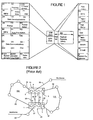
- Figure 1 is a diagram showing the byte allocation in the transport overhead (TOH) according to the synchronous optical network (SONET) standard.
- the user signals are converted into a standard electrical format called the synchronous transport signal (STS), which is the equivalent of the optical signal.
- STS-1 frame consists of 90 columns by 9 rows of bytes, the frame length is 125 microseconds. As such, STS-1 has a rate of 51.840 Mb/s. Higher rates (STS-N, STS-Nc) are built from this one, and lower rates are subsets of this.
- the add/drop multiplexer multiplexes various STS-N input streams onto optical fiber channels.
- a SONET frame comprises a transport overhead (TOH) consisting of three columns and 9 rows, and a synchronous payload envelope (SPE) comprising an 87 columns, one column for the path overhead (POH) and 86 columns for the payload.
- the TOH includes a section overhead field (SOH) consisting of three columns and three rows (3x3), and a line overhead (LOH) field consisting of three columns and six rows (3x6).
- the section layer deals with the transport of multiplexed signals across the physical medium.
- a section is a portion of the transmission facility between two section terminating equipments (STE), such as regenerators and terminals.
- STE section terminating equipments
- the SOH includes framing bytes A1, A2, which consist of a unique bit sequence indicating the beginning of an STS-1 frame.
- Byte J0 is now used to physically identify the fibers and is present in the first STS-1 (STS-1 #1) of a STS-N signal, while byte Z0 represents an additional growth byte in all remaining STS-1s (STS-1 #2 to STS-1 #N).
- Section error monitoring byte B1 is used to determine if a transmission error has occurred over a section.
- Byte B1 is defined for STS-1 #1.
- a compounded bit interleaved parity (BIP-8) code is placed in the B1 byte of STS-1 before scrambling. Its value is an 8-bit code using even parity, calculated over all bits of the previous STS-N frame after scrambling.
- LOW Local orderwire
- Byte F1 is the section user byte set aside for the network provider's purposes. It is passed from one section level entity to another and is terminated at all section level equipment. It can be read/written at each section terminating equipment, and is defined only for STS-1 #1.
- the section data communication channel (DCC) bytes D1, D2 and D3 provide a 192 Kb/s data channel between section entities, which is used for alarms, controls, monitoring, administration, and other communication needs. It is available for internally generated, externally generated and manufacturer specific messages. These bytes are defined only for STS-1 #1.
- the line layer, or multiplex section, of SONET standard provides synchronization and multiplexing for the path layer.
- a line is a portion of the transmission facility between two consecutive line terminating equipments (LTE), which could be add-drop multiplexers (ADM) or terminals (TM).
- ADM add-drop multiplexers
- TM terminals
- the LOH includes payload pointers H1, H2 used to specify the beginning of the synchronous payload envelope (SPE) within the frame.
- H1 and H2 are also used to accommodate frequency offsets between the received STS-N frame and the local system frame. As well, these bytes are used to indicate concatenation and STS-1 path alarm inhibit signal (AIS).
- Pointer H3 is defined for negative frequency justification, in which case it carries an extra SPE byte.
- Byte B2 is for line error monitoring and is provided in all STS-1s signals in a STS-N. Its role is similar to that of byte B1.
- Automatic Protection Switching (APS) bytes K1 and K2 are used for signalling between line level entities for automatic protection switching, for indicating line Alarm Inhibit Signal (AIS) and Line Remote Defect Indicator (RDI).
- Line Data Communication Channel (DCC) bytes D4 to D12 provide a 576 Kb/s message channel between line entities for OAM&P information, available for internally generated, externally generated and manufacturer-specific messages.
- Bytes S1/Z1 and Z2/M1 are defined depending on the position of the STS-1 in an STS-N signal.
- S1 is the synchronization message for STS-1 #1
- Z1 is a growth byte in STS-1 #2-48 of an STS-192.
- Byte M1 is used for a line layer far-end block error (FEBE) function in STS-1 #7 of a STS-N
- Z2 is the growth byte in STS-1 #1-6, and 8-48 of an STS-192.
- express orderwire (EOW) byte E2 provides a 64 Kb/s for use by craftpersons interconnecting only line entities.
- the path layer of SONET deals with the transport of services, such as DS1 or DS3, between path terminating equipments (PTE).
- the main function of the path layer is to map the services and path overhead (POH) into STS-1s, which is the format required by the line layer.
- Trace byte J1 is used to identify that the correct connection was made between the two end points of the path; it is a user programmable byte that repetitively transmits a 64-byte fixed length string so that a receiving terminal in a path can verify its continued connection to the intended transmitter.
- the path BIP-8 code, the B3 byte, uses even parity calculated over all bits of the previous STS-SPE before scrambling.
- Signal label byte C2 is used to indicate the type of payload mapping and number of constituent failed virtual tributaries (VTs).
- Byte G1 is used to transmit path status information from the destination to the origination equipment, and permits the status and performance of the complete duplex path to be monitored at either end, or at any point along the path.
- Byte F2 is allocated for network provider communication purposes between STS path terminating elements.
- Multiframe indicator byte H4 is used for VT structured payloads. It indicates a variety of different superframes for use by certain sub-STS-1 payloads. Bytes Z3 and Z4 are allocated for future and as yet undefined purposes. Byte Z5 is used for two purposes: tandem connection maintenance error count and a 32 kb/s path data communications channel.
- Figure 2 illustrates an example of a fiber optic network involving two sites, 10 and 20 .
- NEs 2 , 4 , 6 and 8 at site 10 are respectively connected to NEs 1 , 3 , 5 , 7 at site 20 .
- NEs 1 and 2 may, for example, communicate with a ring 100 , NEs 3 and 4 , with a backbone linear system including spans 26 , 27 , 23 , and 28 , while NEs 7 and 8 may be part of another ring 110 .
- a local connection 24 is provided between NEs 5 and 6 . There could be repeaters between the sites, not illustrated on Figure 2.
- Each span 22 , 23 , 24 and 25 is a 4-fiber span for bidirectional, working and protection traffic, which results in 16 fibers being deployed between sites 10 and 20 .
- the fiber count between rates 10 and 20 may be reduced using the WDM approach or the transparent transport solution according to the invention. A comparison between these two solutions follows.
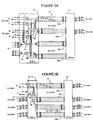
- Figure 3A shows the equipment necessary at site 10 (site A) of the network of Figure 2 with the WDM approach where 8 channels ⁇ 1 to ⁇ 8 are transmitted over a two-fiber span 30a , 30b . Only the connections for nodes 2 and 4 are shown for simplification.
- Working signals of wavelengths ⁇ 1 to ⁇ 4 leave site 10 (forward direction), while working signals ⁇ 5 to ⁇ 8 arrive at site 10 from site 20 (reverse direction).
- Fiber 30a accommodates the working traffic, while fiber 30b accommodates the protection traffic. This arrangement requires four optical splitters/containers for reducing the fiber count from sixteen to four.
- Multi-wavelength splitter/combiner 43 consolidates the working forward traffic, multi-wavelength splitter/combiner 44 , the working reverse traffic, splitter/combiner 45 , the protection forward traffic and splitter/combiner 46 , the protection reverse traffic.
- bidirectional couplers 41 and 42 are necessary to accommodate the bidirectional nature of the traffic.
- FIG 3B illustrates the regenerator site for the WDM approach, shown in Figure 3A.
- the channels For using only two fibers between sites 10 and 20 , the channels must be separated before regeneration and re-assembled after. Thus, a bidirectional coupler 11 is necessary to separate the working forward and working reverse traffic.
- the working forward channels I 1 -I 4 are then separated using multi-wavelength splitter/combiner 12 , individually amplified by four regenerators 34-37 , re-assembled after regeneration using multi-wavelength splitter/combiner 12' , and combined with the reverse working traffic using coupler 13 . Similar operations are performed for the working reverse traffic, using multi-wavelength splitter/combiners 14' and 14 before and after regeneration.
- An additional pair of bidirectional couplers 15 , 17 is necessary for separating/combining the protection traffic for the forward and reverse directions.
- the protection forward channels are separated/re-assembled using multi-wavelength splitter/combiners 16 and 16' , while the reverse protection channels are separated/combined using bidirectional couplers 18' and 18 .
- Each protection channel is individually amplified by regenerators 34-37 .
- wavelength specific transmitters are required in each NE 2 , 4 , 6 , and 8 of site 10 and 1 , 3 , 5 and 7 of site 20 . These transmitters may not have been provided initially, and the existing transmitters would require upgrading.
- Figure 4A shows the configuration according to the invention, where the four fiber spans 22-25 shown in Figure 2 between the two sites 10 and 20 are replaced by a high rate span 30a , 30b . If each span 22-25 carries an OC-48, the high rate span 30 would carry traffic at OC-192 rate.
- bidirectional couplers 41 and 42 are still used to reduce the fiber count from four to two fibers.
- no multi-wavelength splitters/combiners are necessary at site A.
- wavelength-specific OC-192 transmitters are required for providing the forward OC-192 channel I F and reverse OC-192 channel I R , only one quarter as many are needed.
- Figure 4B shows a configuration when regeneration of the high speed signal is necessary in the case of long inter-office spans. Unlike the case illustrated in Figure 3B for the WDM approach, only one 2-channel bidirectional regenerator 34 is necessary, resulting also in further savings on couplers. Thus, at the regenerator site, the working forward and reverse channels are separated by a bidirectional coupler 11 , and then combined by bidirectional coupler 13 , couplers 15 and 17 being used in a similar way for regenerating the protection traffic. No splitter/combiner, such as 12 , 14 , 16 , 18 , 12' , 14' , 16' and 18' are needed.
- the invention is not limited to identical trib bit rates.
- the input tribs described in this invention have the same rate for an easier understanding of the general concept.
- the invention is not limited to SONET signals, but it can be applied to other transport technologies.
- the invention is not limited to OC-3/OC-12/OC-48 signals, carried in a OC-192 supercarrier, but it is also adaptable to other bit rates, in accordance with the HW and SW evolution of transport networks.
- each site 10, 20 is equipped with a (TMux).
- Figure 4A shows TMux 40 at site 10 connected to nodes 2 , 4 , 6 and 8 , T-Mux 50 (not shown) being provided at site 20 and connected to nodes 1 , 3 , 5 and 7 .
- the TMuxs according to the invention allow for an unchanged operation of NEs 1 to 8 in the respective lower rate networks.
- the signals input at site 10 are multiplexed by TMux 40 to a high rate signal (supercarrier) which is transmitted over optical fiber 30a , demultiplexed at site 20 by a corresponding TMux 50 (not shown in Figure 4A), and output to the respective networks. Similar operations take place for the reverse channels and for the forward and reverse protection traffic.
- the bytes of the trib TOH/POH are manipulated by the TMuxs such as to not alter the provisioning of the existing systems, to maintain the protection switching, to effect line maintenance signalling, section/ line/ path performance monitoring, and to provide sufficient performance information for fault isolation, as detailed next.
- the APS bytes K1 and K2 of all tributary (trib) systems must be passed between sites 10 and 20 unaltered. Since the K2 byte is passed through, the line AIS and line RDI indications also pass through automatically.
- the routing options for providing trib protection depends on the trib protection scheme, which could be 1:N, 1+1 or 4F-BLSR, and 2F-BLSR.
- FIG. 6 is a block diagram of the TMux illustrating the blocks involved in carrying four OC48 trib systems over an OC-192 from input TMux 40 to output TMux 50 , for the case of a nailed up OC-192 P-channel trib protection type.
- the operation for forward direction is illustrated and disclosed in the following for simplification, the T-Mux pair 40 , 50 operates similarly for the reverse traffic.
- TMux 40 comprises four trib input ports 61 - 64 , each input port for receiving an incoming SONET formatted optical signal OC48 #14 over a respective input span 51 , 53 , 55 , and 57 and converting same to an input STS-48 #14.
- Trib input ports 61 - 64 perform SONET physical layer operations, clock recovery/synthesis, descrambling, framing, manipulating the section overhead and the line overhead, demultiplexing the STS-48, and synchronization of the STS paths with the local clock provided by a synchronization unit 72 , and transmitting the input STS-ls to a STS-1 manager 65 .
- a trib transport overhead (TOH) processor 60 receives the SOH and LOH bytes of all input STS48s and processes these bytes according to Table 2.
- Trib TOH manipulation Byte name Definition
- Trib STS-1 Manipulation A1-2 Framing STS-1 #1 Term. J0 Section Trace STS-1 #1 Term.
- E1 Orderwire STS-1 #1 Passthru F1 User STS-1 #1 Passthru D1-3 Section Datacom STS-1 #1 Passthru Z0 Growth STS-1 #2-48 Term.
- section BIP-8 byte (B1) is terminated as usual, such that the TMux appears as a pseudo-repeater to facilitate fault isolation.
- any section errors that occur on the input span or internal span is replicated at the output span, as it will be disclosed later.
- section datacom bytes D1 to D3, along with bytes E1 (orderwire), and F1 (user byte) of all trib systems must be passed through the input and output TMuxs. Any potential mid-span meet problems encountered at the high speed Mux/trib interface regarding section DCC protocols are avoided by the TMux.
- the line BIP-8 bytes are terminated. Again, any line errors which occur on an input span, for example span 51 , or the internal span 30 , is replicated at the output span, so that the trib systems can perform signal degraded (SD) protection switching as needed, and line performance monitoring.
- SD signal degraded
- the APS bytes are passed through transparently, as stated earlier, to enable normal protection operation on the tributary systems.
- Trib line AIS and RDI maintenance signals thereby pass through also.
- the line FEBE byte is passed through to enable normal performance monitoring.
- the STS payload pointer bytes H1-H3 must be processed to still point to the SPE when the new frame alignment is imposed. Also, they must be manipulated for small frequency offsets via stuff/destuff operations.
- the synchronization byte S1 must be terminated/sourced as it provides information about the timing source being used. Growth bytes Z0 to Z2 are undefined, thus they are terminated.
- a POH monitor 68 accesses the POH of each trib system.
- the trib STS POH is passed through to comply with the definition of the transparency, however some of these bytes are monitored for faults and alarms, as shown in Table 3.
- Trib POH manipulation Byte name Definition Manipulation J1 Path Trace Monitored B3 Path BIP-8 Monitored C2 Signal Label Monitored G1 Path Status Monitored
- a fault detector 70 is provided for detecting errors on the input span and transmitting them to the far-end TMux, so that the trib systems detect errors appropriately.
- Fault detector unit 70 receives the BIP-8 bytes B1, B2 and B3, counts the section/line/path code violations (CV) for the trib systems, and performs comparisons with a provisioned line signal degrade (SD) threshold. Exceeding the threshold constitutes an SD in protection terminology.
- This information is passed to a transmit supercarrier TOH processor (SC TOHP) 66 , which generates a TMux message (TMux Msg) comprising four bytes, one to indicate the bit error rate (BER) of each input span.
- SC TOHP transmit supercarrier TOH processor
- the TMux Msg byte is inserted in the K2 timeslot of STS-1 #9 of each trib system.
- the fault detector 70 also monitors each tributary input for hard failure, and if detected, triggers line AIS insertion over the trib signal portion of the OC-192 SC.
- TMux Msg byte assignment is given in Table 4, together with the rate of uniformly distributed Line CVs for a given BER at OC48 rate.
- TMux Msg Byte Code (hex) Indication (raw BER) Rate of Line CVs 00 unmeasurable BER 01 BER ⁇ 1E-12 02 BER ⁇ 1E-12 1 CV every 3,215,021 frames 03 BER ⁇ 5E-12 1 CV every 643,004 frames 04 BER ⁇ 1E-11 1 CV every 321,502 frames 05 BER ⁇ 5E-11 1 CV every 64,300 frames 06 BER ⁇ 1E-10 1 CV every 32,150 frames 07 BER ⁇ 5E-10 1 CV every 6,430 frames 08 BER ⁇ 1E-09 1 CV every 3215 frames 09 BER ⁇ 5E-09 1 CV every 643 frames 0A BER ⁇ 1E-08 1 CV every 322 frames 0B BER ⁇ 5E-08 1 CV every 64 frames 0C BER ⁇ 1E-07 1 CV every 32 frames
- STS-1 manager unit 65 is responsible with interchanging the STS-1s from the tributaries, in order to permit the use of the SC TOH in STS-1#1.
- Tables 5 and 6 illustrate by way of an example how the STS-ls of OC48/OC-12/OC-3 trib systems are arranged in the OC-192 supercarrier.
- K is an integer giving the number of tribs and N is the rate of the tribs.
- N is the rate of the tribs.
- the OC48 trib feed whose STS-1#1 would coincide with SC STS-1#1 is swapped in entirety (both the OH and the payload) with STS-1#13 (or any STS-1 not normally carrying TOH).
- the trib whose STS-1#1 would coincide with OC-192 STS-1#1 is not supported in the TMux.
- a maximum of 15 OC-12 tribs are supported.
- Figure 7A illustrates how OC-12 tributary systems are carried transparently by an OC-192 SC, while Figure 7B shows OC-3 tributaries.
- the SC TOHP 66 passes the trib TOH bytes from block 60 and aligns each byte into the correct timeslot before passing same to a supercarrier (SC) output port 71 .
- STS-1 manager 65 routes the 4 x 48 component STS-ls received from the respective trib input port to SC output port 71 for multiplexing the STS-ls into the output supercarrier.
- the SC output port 71 receives the output STS-ls from block 65 and the SC TOH from SC TOHP 66 , multiplexes the STS-ls into the supercarrier STS-192, adds the SC TOH, and is also responsible for scrambling, converting the output STS-192 to the optical supercarrier OC-192, and transmitting it on fiber 30 .
- the SC output port 71 also performs clock synthesis based on the local clock from synchronization unit 72 .
- An SC input port 91 at output TMux 50 receives the optical supercarrier OC-192 on fiber span 30 and converts it to an input STS-192.
- SC input port 91 performs SONET physical layer operations, clock recovery/synthesis, descrambling, stripping the SC TOH, demultiplexing, synchronization of the STS paths with the local clock provided by a synchronization unit 92 , and transmitting the incoming STS-1s to a STS-1 manager 85 .
- An SC receive overhead processor (SC ROHP) 86 receives the respective SOH and LOH bytes of the SC TOH and passes the trib TOH to trib TOH processor (TOHP) 80 .
- the trib TOH processor 80 extracts the TMux Msg bytes. Using a look-up table, each TMux value indicates the rate of errors that must be replicated on the outgoing trib signal. The errors are introduced by appropriately inverting B1 and B2 values. The remaining trib TOH is either passed through or generated, as in Table 2.
- a POH monitor 88 accesses the POH bytes, but again, leaves them unchanged. These bytes are only monitored for faults and alarms, as shown in Table 3.
- a fault detector 90 monitors the OC-192 SC TOH for B2 errors and passes this count to the trib TOH processor 80 , which incorporates the OC-192 errors into the corrupted B1 and B2 values sent to each trib output port. For a hard failure on the OC-192 SC, the fault detector triggers the insertion of line AIS on all output tribs via the trib TOH processor.
- STS-1 manager 85 routes the component STS-1s of the supercarrier to a respective output port 81 - 84 for multiplexing the STS-1s into the outgoing OC-48s.
- STS-1 manager 85 also swaps STS-1 #13 back to STS-1 #1, or as the case may be for other granularity of input tributaries.
- a destination trib system receives its respective OC-48 through one of the four trib output ports 81 - 84 .
- Each trib output port 81 - 84 is responsible for receiving the outgoing STS-1s from block 85 , multiplexing the STS-ls into an output STS-48, adding the trib TOH received from block 80 , scrambling, converting the STS-48 signal to the respective outgoing optical signal OC-48, and transmitting it on the respective output span.
- the trib output ports also perform clock synthesis based on the local clock of synchronization unit 92 .
- each TMux is co-located with the trib systems, as seen for example on Figure 4A, each originating trib system 2 , 4 , 6 , and 8 can access its own OWs, user, and datacom channel. Access to the OC-192 E1-2, F1 and D1-D12 bytes is supported by the TMuxs.
- the J0 section trace bytes from the original trib systems could be regenerated at the output TMux trib outputs so that the downstream trib systems still see the same JOs and do not need to change their provisioning.
- the supported trib rates/quantities are four OC-48, 15 OC-12 or 15 OC-3.
- the OC-12 or OC-3 trib whose STS-1 #1 would correspond to STS-1 #1 on the OC-192 line is not supported to avoid TOH conflicts.
- the TMux must replicate signal fail (SF) and signal degrade (SD) conditions which occur on the input span and internal span, at the output span, so that the trib systems may perform protection switching as needed, and performance monitoring.
- SF signal fail
- SD signal degrade
- the output TMux trib must corrupt the B2s such that the combined BER of the tributary input span and the OC-192 internal span is mimicked. This will ensure that the downstream trib system could initiate an SD level protection switch if needed.
- the B1s must also be corrupted to provide consistent performance monitoring counts.
- a degrade on the input span 51 triggers Line FEBE counts to be sent back by the respective destination trib system connected over span 52 to output TMux 50 .
- a degrade on the internal span 30 triggers the Line FEBE counts to be sent back by all destination trib systems.
- TMux trib output When a line failure condition occurs on either tributary input span 51 , 53 , 55 , or 57 , or the internal span 30 , the output TMux trib output must send Line Alarm Inhibit Signal (AIS). This will ensure that the downstream trib system will initiate protection.
- AIS Line Alarm Inhibit Signal
- An SF condition on the input span triggers Line RDI to be sent back by the destination trib system.
- An SF on the internal span triggers the Line RDI to be sent back by all the destination trib systems.
- line RDI is sent back by all the destination trib systems.
- the SF on the input span is not silent, input TMux 40 alarms it.
- Line RDI is sent back by all destination trib systems. Again, the SD on the input span is not silent, input TMux 40 alarms it.
- Line RDI is sent back by the respective destination trib system and Line FEBEs are counted by the other destination trib systems.
Applications Claiming Priority (2)
| Application Number | Priority Date | Filing Date | Title |
|---|---|---|---|
| US847526 | 1997-04-24 | ||
| US08/847,526 US5841760A (en) | 1997-04-24 | 1997-04-24 | Transparent multiplexer/demultiplexer |
Publications (3)
| Publication Number | Publication Date |
|---|---|
| EP0874488A2 true EP0874488A2 (de) | 1998-10-28 |
| EP0874488A3 EP0874488A3 (de) | 2001-03-14 |
| EP0874488B1 EP0874488B1 (de) | 2007-08-01 |
Family
ID=25300850
Family Applications (1)
| Application Number | Title | Priority Date | Filing Date |
|---|---|---|---|
| EP98303100A Expired - Lifetime EP0874488B1 (de) | 1997-04-24 | 1998-04-22 | Transparenter Multiplexer/Demultiplexer |
Country Status (5)
| Country | Link |
|---|---|
| US (1) | US5841760A (de) |
| EP (1) | EP0874488B1 (de) |
| JP (1) | JPH10341216A (de) |
| CA (1) | CA2234790C (de) |
| DE (1) | DE69838157T2 (de) |
Cited By (10)
| Publication number | Priority date | Publication date | Assignee | Title |
|---|---|---|---|---|
| EP1037421A2 (de) * | 1999-03-18 | 2000-09-20 | Fujitsu Limited | Übertragungsverfahren und -vorrichtung zur Übertragung von niedriggeschwindigkeitssignalen, die einen hochgeschwindigkeits-SDH Rahmen verwenden |
| EP1100222A2 (de) * | 1999-11-12 | 2001-05-16 | Nortel Networks Limited | Detektion von Fehlern in der vorigen Sektion für eine transparente Untersystemseinheit |
| EP1143650A1 (de) * | 1999-10-28 | 2001-10-10 | Fujitsu Limited | Nachrichtenübertragungssystem |
| EP1198087A1 (de) * | 2000-09-08 | 2002-04-17 | Lucent Technologies Inc. | Verfahren und Schaltung zur Bereitstellung von Signalen unterschiedlicher Datenrate in optischen Übertragungssystemen |
| EP1052794A3 (de) * | 1999-05-10 | 2002-05-22 | Nortel Networks Limited | Protokollunabhängige unterrätige Vorrichtung |
| EP1305883A2 (de) * | 2000-06-14 | 2003-05-02 | Vitesse Semiconductor Corporation | Transparent-transport-overhead-abbildung |
| EP1335514A1 (de) * | 2002-02-12 | 2003-08-13 | Lucent Technologies Inc. | Verfahren und Vorrichtung zur Übertragung eines SDH/SONET Client-Signals als Dienstleistung |
| US6792005B1 (en) | 2000-09-08 | 2004-09-14 | Lucent Technologies Inc. | Timing circuitry for muxing/demuxing of optical communication signals |
| EP1548977A1 (de) * | 2002-09-23 | 2005-06-29 | Huawei Technologies Co., Ltd. | Verfahren zum transparenten senden der verwaltungsinformationen von optischen synchron-digitalhierarchieeinrichtungen mehrerer hersteller |
| US7586921B2 (en) * | 2000-05-26 | 2009-09-08 | Alcatel | Method of transmitting synchronous transport modules via a synchronous transport network |
Families Citing this family (34)
| Publication number | Priority date | Publication date | Assignee | Title |
|---|---|---|---|---|
| JP3663253B2 (ja) * | 1996-05-31 | 2005-06-22 | 株式会社日立コミュニケーションテクノロジー | 多重化伝送装置 |
| US6298038B1 (en) * | 1997-04-24 | 2001-10-02 | Nortel Networks Limited | Transparent transport |
| US6396852B1 (en) * | 1997-11-18 | 2002-05-28 | Jane Marie Simmons | Ring bundling in the design of rings for telecommunications networks |
| EP0920152A3 (de) * | 1997-11-27 | 2002-09-18 | Hitachi, Ltd. | Verfahren und Vorrichtung zur Multiplexübertragung |
| US6205158B1 (en) * | 1997-12-19 | 2001-03-20 | Nortel Networks Limited | Network architectures with transparent transport capabilities |
| US6195367B1 (en) * | 1997-12-31 | 2001-02-27 | Nortel Networks Limited | Architectural arrangement for bandwidth management in large central offices |
| US6526021B1 (en) * | 1998-04-03 | 2003-02-25 | Alcatel Network Systems, Inc. | Clear channel 1:N SONET transport system and method |
| US6266345B1 (en) * | 1998-04-24 | 2001-07-24 | Xuan Zhon Ni | Method and apparatus for dynamic allocation of bandwidth to data with varying bit rates |
| US7924706B1 (en) | 1999-03-22 | 2011-04-12 | Cisco Technology, Inc. | Method and apparatus for controlling the operation of a flexible cross-connect system |
| US6865181B1 (en) * | 1999-03-22 | 2005-03-08 | Cisco Technology, Inc. | Method and apparatus for routing telecommunications signals |
| US7292608B1 (en) * | 1999-11-30 | 2007-11-06 | Cisco Technology, Inc. | Method and apparatus for transferring synchronous optical network/synchronous digital hierarchy(SONET/SDH) frames on parallel transmission links |
| CA2293521A1 (en) * | 1999-12-29 | 2001-06-29 | Phil Campbell | Asynchronous payload mapping using direct phase transfer |
| IT1317614B1 (it) * | 2000-03-17 | 2003-07-15 | Cit Alcatel | Metodo ed apparato per trasmettere/ricevere segnali digitali dilivello stm-4(sdh) o sts-12(sonet) su due portanti rf in una sezione |
| US6870860B1 (en) * | 2000-04-19 | 2005-03-22 | Ciena Corporation | Semi-transparent time division multiplexer/demultiplexer |
| US7035204B1 (en) | 2000-07-26 | 2006-04-25 | Cicso Technology, Inc. | Method and apparatus for rerouting telecommunications signals |
| US6826200B1 (en) * | 2000-11-29 | 2004-11-30 | Nortel Networks Limited | Combiner/TMUX simulated B1 transparency in fiber optic networks running SONET |
| US6859453B1 (en) | 2000-12-19 | 2005-02-22 | Nortel Networks Limited | Clear channel access methods, apparatuses, media and signals |
| US6826201B2 (en) * | 2000-12-19 | 2004-11-30 | Nortel Networks Limited | Multiplexing SONET /SDH data streams using independent encoding schemes |
| US6885632B1 (en) * | 2000-12-21 | 2005-04-26 | Nortel Networks Limited | Method and system for signal degrade (SD) information passthrough in T-Mux systems |
| US20020085590A1 (en) * | 2000-12-29 | 2002-07-04 | Booth Bradley J. | Method and apparatus for inserting user data into sonet data communications channel |
| US7068663B1 (en) * | 2001-01-23 | 2006-06-27 | Cisco Technology, Inc. | Path routing and provisioning method and apparatus |
| US7016378B1 (en) | 2001-01-26 | 2006-03-21 | Ciena Corporation | Method and system for automatically provisioning an overhead byte |
| US7227844B1 (en) * | 2001-02-21 | 2007-06-05 | Cisco Technology, Inc. | Non-standard concatenation mapping for payloads |
| US6580731B1 (en) | 2001-05-18 | 2003-06-17 | Network Elements, Inc. | Multi-stage SONET overhead processing |
| US7002967B2 (en) | 2001-05-18 | 2006-02-21 | Denton I Claude | Multi-protocol networking processor with data traffic support spanning local, regional and wide area networks |
| US7362759B2 (en) * | 2001-05-21 | 2008-04-22 | Intel Corporation | Method and apparatus for encoding information |
| US7158517B2 (en) * | 2001-05-21 | 2007-01-02 | Intel Corporation | Method and apparatus for frame-based protocol processing |
| US7180913B2 (en) * | 2001-07-25 | 2007-02-20 | Nortel Networks Limited | Transparent error count transfer method and apparatus |
| US7075953B2 (en) * | 2001-07-30 | 2006-07-11 | Network-Elements, Inc. | Programmable SONET framing |
| US7633858B2 (en) * | 2001-09-10 | 2009-12-15 | Ciena Corporation | Providing embedded protection in a network cross-connect device for SONET networks |
| US20030174739A1 (en) * | 2002-03-12 | 2003-09-18 | Gagnon Ronald J. | Termination equipment with an overhead processor programmable to pass through proprietary usage data in selected overhead data slots |
| US7440404B2 (en) * | 2004-02-24 | 2008-10-21 | Lucent Technologies Inc. | Load balancing method and apparatus for ethernet over SONET and other types of networks |
| CN100373847C (zh) * | 2004-12-14 | 2008-03-05 | 华为技术有限公司 | 在光传送网中传输低速率业务信号的方法 |
| CN101159495B (zh) * | 2006-10-08 | 2012-07-04 | 华为技术有限公司 | 无源光纤网络中信号传送系统、设备及方法 |
Citations (2)
| Publication number | Priority date | Publication date | Assignee | Title |
|---|---|---|---|---|
| US5365510A (en) * | 1992-04-09 | 1994-11-15 | Northern Telecom Limited | Communications system with a single protection loop |
| WO1996008902A1 (en) * | 1994-09-12 | 1996-03-21 | Dsc Communications Corporation | Integrated multi-fabric digital cross-connect integrated office links |
Family Cites Families (4)
| Publication number | Priority date | Publication date | Assignee | Title |
|---|---|---|---|---|
| US5355362A (en) * | 1992-10-26 | 1994-10-11 | Nec America, Inc. | Digital loop carrier system |
| JPH07123067A (ja) * | 1993-10-20 | 1995-05-12 | Hitachi Ltd | 多重化装置 |
| US5675580A (en) * | 1993-12-30 | 1997-10-07 | Dsc Communications Corporation | Processor device for terminating and creating synchronous transport signals |
| US5436890A (en) * | 1993-12-30 | 1995-07-25 | Dsc Communications Corporation | Integrated multi-rate cross-connect system |
-
1997
- 1997-04-24 US US08/847,526 patent/US5841760A/en not_active Expired - Lifetime
-
1998
- 1998-04-15 CA CA002234790A patent/CA2234790C/en not_active Expired - Lifetime
- 1998-04-22 DE DE69838157T patent/DE69838157T2/de not_active Expired - Lifetime
- 1998-04-22 EP EP98303100A patent/EP0874488B1/de not_active Expired - Lifetime
- 1998-04-24 JP JP10115087A patent/JPH10341216A/ja active Pending
Patent Citations (2)
| Publication number | Priority date | Publication date | Assignee | Title |
|---|---|---|---|---|
| US5365510A (en) * | 1992-04-09 | 1994-11-15 | Northern Telecom Limited | Communications system with a single protection loop |
| WO1996008902A1 (en) * | 1994-09-12 | 1996-03-21 | Dsc Communications Corporation | Integrated multi-fabric digital cross-connect integrated office links |
Cited By (21)
| Publication number | Priority date | Publication date | Assignee | Title |
|---|---|---|---|---|
| US6674771B1 (en) | 1999-03-18 | 2004-01-06 | Fujitsu Limited | Transmission method and apparatus for transmitting low-speed SDH signals using a high-speed SDH frame |
| EP1037421A2 (de) * | 1999-03-18 | 2000-09-20 | Fujitsu Limited | Übertragungsverfahren und -vorrichtung zur Übertragung von niedriggeschwindigkeitssignalen, die einen hochgeschwindigkeits-SDH Rahmen verwenden |
| EP1037421A3 (de) * | 1999-03-18 | 2002-10-16 | Fujitsu Limited | Übertragungsverfahren und -vorrichtung zur Übertragung von niedriggeschwindigkeitssignalen, die einen hochgeschwindigkeits-SDH Rahmen verwenden |
| EP1052794A3 (de) * | 1999-05-10 | 2002-05-22 | Nortel Networks Limited | Protokollunabhängige unterrätige Vorrichtung |
| US6522671B1 (en) | 1999-05-10 | 2003-02-18 | Nortel Networks Limited | Protocol independent sub-rate device |
| EP1143650A1 (de) * | 1999-10-28 | 2001-10-10 | Fujitsu Limited | Nachrichtenübertragungssystem |
| US7957429B2 (en) | 1999-10-28 | 2011-06-07 | Fujitsu Limited | Transmission system |
| EP1143650A4 (de) * | 1999-10-28 | 2004-11-24 | Fujitsu Ltd | Nachrichtenübertragungssystem |
| EP1100222A3 (de) * | 1999-11-12 | 2003-01-22 | Nortel Networks Limited | Detektion von Fehlern in der vorigen Sektion für eine transparente Untersystemseinheit |
| EP1100222A2 (de) * | 1999-11-12 | 2001-05-16 | Nortel Networks Limited | Detektion von Fehlern in der vorigen Sektion für eine transparente Untersystemseinheit |
| US6937614B1 (en) | 1999-11-12 | 2005-08-30 | Nortel Networks Limited | Transparent port for high rate networking |
| US7586921B2 (en) * | 2000-05-26 | 2009-09-08 | Alcatel | Method of transmitting synchronous transport modules via a synchronous transport network |
| EP1305883A2 (de) * | 2000-06-14 | 2003-05-02 | Vitesse Semiconductor Corporation | Transparent-transport-overhead-abbildung |
| EP1305883A4 (de) * | 2000-06-14 | 2006-08-23 | Vitesse Semiconductor Corp | Transparent-transport-overhead-abbildung |
| EP1198087A1 (de) * | 2000-09-08 | 2002-04-17 | Lucent Technologies Inc. | Verfahren und Schaltung zur Bereitstellung von Signalen unterschiedlicher Datenrate in optischen Übertragungssystemen |
| US6792005B1 (en) | 2000-09-08 | 2004-09-14 | Lucent Technologies Inc. | Timing circuitry for muxing/demuxing of optical communication signals |
| US6822975B1 (en) | 2000-09-08 | 2004-11-23 | Lucent Technologies | Circuitry for mixed-rate optical communication networks |
| EP1335514A1 (de) * | 2002-02-12 | 2003-08-13 | Lucent Technologies Inc. | Verfahren und Vorrichtung zur Übertragung eines SDH/SONET Client-Signals als Dienstleistung |
| US7324563B2 (en) | 2002-02-12 | 2008-01-29 | Lucent Technologies Inc | Method and apparatus for transporting a SDH/SONET client signal as a service |
| EP1548977A1 (de) * | 2002-09-23 | 2005-06-29 | Huawei Technologies Co., Ltd. | Verfahren zum transparenten senden der verwaltungsinformationen von optischen synchron-digitalhierarchieeinrichtungen mehrerer hersteller |
| EP1548977A4 (de) * | 2002-09-23 | 2007-04-25 | Huawei Tech Co Ltd | Verfahren zum transparenten senden der verwaltungsinformationen von optischen synchron-digitalhierarchieeinrichtungen mehrerer hersteller |
Also Published As
| Publication number | Publication date |
|---|---|
| DE69838157D1 (de) | 2007-09-13 |
| JPH10341216A (ja) | 1998-12-22 |
| CA2234790C (en) | 2002-05-14 |
| CA2234790A1 (en) | 1998-10-24 |
| EP0874488B1 (de) | 2007-08-01 |
| DE69838157T2 (de) | 2007-11-15 |
| US5841760A (en) | 1998-11-24 |
| EP0874488A3 (de) | 2001-03-14 |
Similar Documents
| Publication | Publication Date | Title |
|---|---|---|
| US5841760A (en) | Transparent multiplexer/demultiplexer | |
| EP0874487B1 (de) | Transparente Übertragung in einem Nachrichtenübertragungssystem | |
| US7386012B2 (en) | Multiplex transmission apparatuses, multiplex transmission networks, and operation method therefor | |
| US6721268B1 (en) | Method and apparatus for multiplex transmission | |
| US8699886B2 (en) | Externally synchronized optical transport network systems and associated methods | |
| US6205158B1 (en) | Network architectures with transparent transport capabilities | |
| US6188667B1 (en) | Transport interface for performing protection switching of telecommunications traffic | |
| US5822299A (en) | Path protection in a telecommunications network | |
| US6870860B1 (en) | Semi-transparent time division multiplexer/demultiplexer | |
| US7161899B2 (en) | Interlocking SONET/SDH network architecture | |
| JP2005531988A (ja) | トランスペアレントでフレキシブルな連結 | |
| US6349092B1 (en) | BLSR node extension | |
| JP2000269912A (ja) | 高速sdh信号による低速sdh信号の伝送方法と伝送装置 | |
| EP3396880A1 (de) | Methode zur abbilden digitaler signale in ein optisches verkehrsnetz und entsprechendes netzwerk element, optisches telekommunikationsnetz und rahmen für optisches telekommunikationsnetz | |
| ITMI20000545A1 (it) | Metodo ed apparato per trasmettere/ricevere segnali digitali di livello stm-4(sdh) o sts-12(sonet) su due portanti rf in una sezione di rige | |
| US7526197B2 (en) | Utilizing the protecting bandwidth in a SONET network | |
| US6901082B1 (en) | Method and apparatus for communicating information | |
| US20030058789A1 (en) | SDH ring network | |
| US7792132B2 (en) | Framer/mapper/multiplexor device with 1+1 and equipment protection | |
| JP3496536B2 (ja) | 多重化伝送方法及び装置 | |
| CA2261448C (en) | Network architectures with transparent transport capabilities | |
| Bhatt | Synchronous Digital Hierarchy and its Implementation in Communication Networks | |
| JP3664484B2 (ja) | 多重伝送装置および多重分離装置 | |
| Jain | Carrier Networking Technologies |
Legal Events
| Date | Code | Title | Description |
|---|---|---|---|
| PUAI | Public reference made under article 153(3) epc to a published international application that has entered the european phase |
Free format text: ORIGINAL CODE: 0009012 |
|
| AK | Designated contracting states |
Kind code of ref document: A2 Designated state(s): DE FR GB |
|
| AX | Request for extension of the european patent |
Free format text: AL;LT;LV;MK;RO;SI |
|
| RAP3 | Party data changed (applicant data changed or rights of an application transferred) |
Owner name: NORTEL NETWORKS CORPORATION |
|
| RAP1 | Party data changed (applicant data changed or rights of an application transferred) |
Owner name: NORTEL NETWORKS LIMITED |
|
| PUAL | Search report despatched |
Free format text: ORIGINAL CODE: 0009013 |
|
| AK | Designated contracting states |
Kind code of ref document: A3 Designated state(s): AT BE CH CY DE DK ES FI FR GB GR IE IT LI LU MC NL PT SE |
|
| AX | Request for extension of the european patent |
Free format text: AL;LT;LV;MK;RO;SI |
|
| 17P | Request for examination filed |
Effective date: 20010914 |
|
| AKX | Designation fees paid |
Free format text: DE FR GB |
|
| RAP1 | Party data changed (applicant data changed or rights of an application transferred) |
Owner name: NORTEL NETWORKS LIMITED |
|
| GRAP | Despatch of communication of intention to grant a patent |
Free format text: ORIGINAL CODE: EPIDOSNIGR1 |
|
| GRAS | Grant fee paid |
Free format text: ORIGINAL CODE: EPIDOSNIGR3 |
|
| GRAA | (expected) grant |
Free format text: ORIGINAL CODE: 0009210 |
|
| AK | Designated contracting states |
Kind code of ref document: B1 Designated state(s): DE FR GB |
|
| REG | Reference to a national code |
Ref country code: GB Ref legal event code: FG4D |
|
| REF | Corresponds to: |
Ref document number: 69838157 Country of ref document: DE Date of ref document: 20070913 Kind code of ref document: P |
|
| ET | Fr: translation filed | ||
| PLBE | No opposition filed within time limit |
Free format text: ORIGINAL CODE: 0009261 |
|
| STAA | Information on the status of an ep patent application or granted ep patent |
Free format text: STATUS: NO OPPOSITION FILED WITHIN TIME LIMIT |
|
| 26N | No opposition filed |
Effective date: 20080506 |
|
| REG | Reference to a national code |
Ref country code: GB Ref legal event code: 732E Free format text: REGISTERED BETWEEN 20101230 AND 20110105 |
|
| REG | Reference to a national code |
Ref country code: FR Ref legal event code: TP |
|
| REG | Reference to a national code |
Ref country code: DE Ref legal event code: R082 Ref document number: 69838157 Country of ref document: DE Representative=s name: PATENTANWAELTE WALLACH, KOCH & PARTNER, DE |
|
| REG | Reference to a national code |
Ref country code: DE Ref legal event code: R082 Ref document number: 69838157 Country of ref document: DE Representative=s name: PATENTANWAELTE WALLACH, KOCH, DR. HAIBACH, FEL, DE Effective date: 20120213 Ref country code: DE Ref legal event code: R082 Ref document number: 69838157 Country of ref document: DE Representative=s name: PATENTANWAELTE WALLACH, KOCH & PARTNER, DE Effective date: 20120213 Ref country code: DE Ref legal event code: R081 Ref document number: 69838157 Country of ref document: DE Owner name: CIENA LUXEMBOURG S.A.R.L., LU Free format text: FORMER OWNER: NORTEL NETWORKS LTD., ST. LAURENT, QUEBEC, CA Effective date: 20120213 Ref country code: DE Ref legal event code: R081 Ref document number: 69838157 Country of ref document: DE Owner name: CIENA LUXEMBOURG S.A.R.L., LU Free format text: FORMER OWNER: NORTEL NETWORKS LTD., ST. LAURENT, CA Effective date: 20120213 |
|
| REG | Reference to a national code |
Ref country code: FR Ref legal event code: PLFP Year of fee payment: 18 |
|
| REG | Reference to a national code |
Ref country code: FR Ref legal event code: PLFP Year of fee payment: 19 |
|
| REG | Reference to a national code |
Ref country code: FR Ref legal event code: PLFP Year of fee payment: 20 |
|
| PGFP | Annual fee paid to national office [announced via postgrant information from national office to epo] |
Ref country code: GB Payment date: 20170419 Year of fee payment: 20 Ref country code: FR Payment date: 20170419 Year of fee payment: 20 Ref country code: DE Payment date: 20170419 Year of fee payment: 20 |
|
| REG | Reference to a national code |
Ref country code: DE Ref legal event code: R071 Ref document number: 69838157 Country of ref document: DE |
|
| REG | Reference to a national code |
Ref country code: GB Ref legal event code: PE20 Expiry date: 20180421 |
|
| PG25 | Lapsed in a contracting state [announced via postgrant information from national office to epo] |
Ref country code: GB Free format text: LAPSE BECAUSE OF EXPIRATION OF PROTECTION Effective date: 20180421 |