EP0874252B1 - Faseroptischer Wellenlängen-Multiplexer-Demultiplexer - Google Patents
Faseroptischer Wellenlängen-Multiplexer-Demultiplexer Download PDFInfo
- Publication number
- EP0874252B1 EP0874252B1 EP98400638A EP98400638A EP0874252B1 EP 0874252 B1 EP0874252 B1 EP 0874252B1 EP 98400638 A EP98400638 A EP 98400638A EP 98400638 A EP98400638 A EP 98400638A EP 0874252 B1 EP0874252 B1 EP 0874252B1
- Authority
- EP
- European Patent Office
- Prior art keywords
- index
- core
- multiplexer
- optical
- demultiplexer
- Prior art date
- Legal status (The legal status is an assumption and is not a legal conclusion. Google has not performed a legal analysis and makes no representation as to the accuracy of the status listed.)
- Expired - Lifetime
Links
- 230000003287 optical effect Effects 0.000 title claims description 19
- 239000000835 fiber Substances 0.000 claims description 57
- 239000013307 optical fiber Substances 0.000 claims description 17
- 230000003247 decreasing effect Effects 0.000 claims description 5
- 238000005253 cladding Methods 0.000 description 5
- 229920000297 Rayon Polymers 0.000 description 4
- 239000002964 rayon Substances 0.000 description 4
- 230000003595 spectral effect Effects 0.000 description 4
- XUIMIQQOPSSXEZ-UHFFFAOYSA-N Silicon Chemical compound [Si] XUIMIQQOPSSXEZ-UHFFFAOYSA-N 0.000 description 3
- 230000005540 biological transmission Effects 0.000 description 2
- 238000002955 isolation Methods 0.000 description 2
- 230000000644 propagated effect Effects 0.000 description 2
- 229910052710 silicon Inorganic materials 0.000 description 2
- 239000010703 silicon Substances 0.000 description 2
- 239000000758 substrate Substances 0.000 description 2
- 230000008878 coupling Effects 0.000 description 1
- 238000010168 coupling process Methods 0.000 description 1
- 238000005859 coupling reaction Methods 0.000 description 1
- 230000004907 flux Effects 0.000 description 1
- 238000009434 installation Methods 0.000 description 1
- 238000000926 separation method Methods 0.000 description 1
Images


Classifications
-
- G—PHYSICS
- G02—OPTICS
- G02B—OPTICAL ELEMENTS, SYSTEMS OR APPARATUS
- G02B6/00—Light guides; Structural details of arrangements comprising light guides and other optical elements, e.g. couplings
- G02B6/02—Optical fibres with cladding with or without a coating
- G02B6/028—Optical fibres with cladding with or without a coating with core or cladding having graded refractive index
- G02B6/0281—Graded index region forming part of the central core segment, e.g. alpha profile, triangular, trapezoidal core
-
- G—PHYSICS
- G02—OPTICS
- G02B—OPTICAL ELEMENTS, SYSTEMS OR APPARATUS
- G02B6/00—Light guides; Structural details of arrangements comprising light guides and other optical elements, e.g. couplings
- G02B6/02—Optical fibres with cladding with or without a coating
- G02B6/036—Optical fibres with cladding with or without a coating core or cladding comprising multiple layers
- G02B6/03605—Highest refractive index not on central axis
- G02B6/03611—Highest index adjacent to central axis region, e.g. annular core, coaxial ring, centreline depression affecting waveguiding
-
- G—PHYSICS
- G02—OPTICS
- G02B—OPTICAL ELEMENTS, SYSTEMS OR APPARATUS
- G02B6/00—Light guides; Structural details of arrangements comprising light guides and other optical elements, e.g. couplings
- G02B6/02—Optical fibres with cladding with or without a coating
- G02B6/036—Optical fibres with cladding with or without a coating core or cladding comprising multiple layers
- G02B6/03616—Optical fibres characterised both by the number of different refractive index layers around the central core segment, i.e. around the innermost high index core layer, and their relative refractive index difference
- G02B6/03638—Optical fibres characterised both by the number of different refractive index layers around the central core segment, i.e. around the innermost high index core layer, and their relative refractive index difference having 3 layers only
- G02B6/03644—Optical fibres characterised both by the number of different refractive index layers around the central core segment, i.e. around the innermost high index core layer, and their relative refractive index difference having 3 layers only arranged - + -
-
- G—PHYSICS
- G02—OPTICS
- G02B—OPTICAL ELEMENTS, SYSTEMS OR APPARATUS
- G02B6/00—Light guides; Structural details of arrangements comprising light guides and other optical elements, e.g. couplings
- G02B6/10—Light guides; Structural details of arrangements comprising light guides and other optical elements, e.g. couplings of the optical waveguide type
- G02B6/12—Light guides; Structural details of arrangements comprising light guides and other optical elements, e.g. couplings of the optical waveguide type of the integrated circuit kind
- G02B6/12007—Light guides; Structural details of arrangements comprising light guides and other optical elements, e.g. couplings of the optical waveguide type of the integrated circuit kind forming wavelength selective elements, e.g. multiplexer, demultiplexer
- G02B6/12009—Light guides; Structural details of arrangements comprising light guides and other optical elements, e.g. couplings of the optical waveguide type of the integrated circuit kind forming wavelength selective elements, e.g. multiplexer, demultiplexer comprising arrayed waveguide grating [AWG] devices, i.e. with a phased array of waveguides
-
- G—PHYSICS
- G02—OPTICS
- G02B—OPTICAL ELEMENTS, SYSTEMS OR APPARATUS
- G02B6/00—Light guides; Structural details of arrangements comprising light guides and other optical elements, e.g. couplings
- G02B6/24—Coupling light guides
- G02B6/26—Optical coupling means
- G02B6/28—Optical coupling means having data bus means, i.e. plural waveguides interconnected and providing an inherently bidirectional system by mixing and splitting signals
- G02B6/293—Optical coupling means having data bus means, i.e. plural waveguides interconnected and providing an inherently bidirectional system by mixing and splitting signals with wavelength selective means
- G02B6/29304—Optical coupling means having data bus means, i.e. plural waveguides interconnected and providing an inherently bidirectional system by mixing and splitting signals with wavelength selective means operating by diffraction, e.g. grating
- G02B6/29316—Light guides comprising a diffractive element, e.g. grating in or on the light guide such that diffracted light is confined in the light guide
- G02B6/29325—Light guides comprising a diffractive element, e.g. grating in or on the light guide such that diffracted light is confined in the light guide of the slab or planar or plate like form, i.e. confinement in a single transverse dimension only
- G02B6/29326—Diffractive elements having focusing properties, e.g. curved gratings
-
- G—PHYSICS
- G02—OPTICS
- G02B—OPTICAL ELEMENTS, SYSTEMS OR APPARATUS
- G02B6/00—Light guides; Structural details of arrangements comprising light guides and other optical elements, e.g. couplings
- G02B6/24—Coupling light guides
- G02B6/26—Optical coupling means
- G02B6/28—Optical coupling means having data bus means, i.e. plural waveguides interconnected and providing an inherently bidirectional system by mixing and splitting signals
- G02B6/293—Optical coupling means having data bus means, i.e. plural waveguides interconnected and providing an inherently bidirectional system by mixing and splitting signals with wavelength selective means
- G02B6/29304—Optical coupling means having data bus means, i.e. plural waveguides interconnected and providing an inherently bidirectional system by mixing and splitting signals with wavelength selective means operating by diffraction, e.g. grating
- G02B6/29316—Light guides comprising a diffractive element, e.g. grating in or on the light guide such that diffracted light is confined in the light guide
- G02B6/29325—Light guides comprising a diffractive element, e.g. grating in or on the light guide such that diffracted light is confined in the light guide of the slab or planar or plate like form, i.e. confinement in a single transverse dimension only
- G02B6/29328—Diffractive elements operating in reflection
-
- G—PHYSICS
- G02—OPTICS
- G02B—OPTICAL ELEMENTS, SYSTEMS OR APPARATUS
- G02B6/00—Light guides; Structural details of arrangements comprising light guides and other optical elements, e.g. couplings
- G02B6/24—Coupling light guides
- G02B6/26—Optical coupling means
- G02B6/28—Optical coupling means having data bus means, i.e. plural waveguides interconnected and providing an inherently bidirectional system by mixing and splitting signals
- G02B6/293—Optical coupling means having data bus means, i.e. plural waveguides interconnected and providing an inherently bidirectional system by mixing and splitting signals with wavelength selective means
- G02B6/29379—Optical coupling means having data bus means, i.e. plural waveguides interconnected and providing an inherently bidirectional system by mixing and splitting signals with wavelength selective means characterised by the function or use of the complete device
- G02B6/2938—Optical coupling means having data bus means, i.e. plural waveguides interconnected and providing an inherently bidirectional system by mixing and splitting signals with wavelength selective means characterised by the function or use of the complete device for multiplexing or demultiplexing, i.e. combining or separating wavelengths, e.g. 1xN, NxM
Definitions
- the present invention relates to a multiplexer-demultiplexer in fiber-optic wavelength, which can be used as component in fiber teletransmission installations optics.
- optical fiber multiplexer-demultiplexer devices in which the input and output light waves are propagated by optical fibers.
- the invention also relates to fiber optic routers in which a variable number of input streams, each having a particular wavelength propagated by optical fibers spatially distinct, are addressed to a possible number different from output fibers.
- a dispersive system realizes the coupling, for a given wavelength between an output fiber and an input fiber.
- Multiplexer-demultiplexers or high-performance routers must simultaneously enable the exploitation of a large number of channels, each of these channels, centered on a wavelength ⁇ , must have a spectral width ⁇ as large as possible, while avoiding any crosstalk.
- crosstalk when part of the energy of a channel is partially mixed with the energy of an adjacent channel. He is well known that crosstalk disrupts communications and that excessive crosstalk rates are in practice unusable.
- the device of the invention will be qualified multiplexer-demultiplexer, it being understood that it can be a multiplexer, a demultiplexer or a router.
- the object of the invention is therefore to propose a multiplexer-demultiplexer which offers improved properties and while retaining a good separation of the channels, improves the spectral width of each of them.
- optical fiber input or output possibly input and output, having index variations that make it possible to obtain the widening of the spectral width sought.
- the invention relates to a multiplexer-demultiplexer in fiber-optic wavelength having a wavelength dispersive system at the least one input fiber and at least one output fiber directly coupled to the dispersive system, the fibers of output having a core and an optical cladding.
- the output and / or input fibers have an index profile with a ring intermediate, located in the optical cladding, optical index of said intermediate ring being greater than the optical index of the sheath optical.
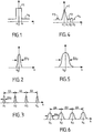
- Figures 1 to 3 are intended to show the operation of transmission devices with a dispersive element of the prior art.
- Single-mode fibers having an index distribution from their center O where the core of the fiber has an index n 1 and the optical cladding of the fiber has an index n 0 .
- the fibers having such an index profile give a wavelength transmission function between an input fiber and an output fiber separated by a dispersive element, as represented on FIG. Figure 2 having approximately a Gaussian shape centered on a wavelength ⁇ o and width halfway ⁇ o .
- the bandwidth of the entire device In the case of a multiplexer or demultiplexer, several fibers, eg output, being associated with an input fiber, the bandwidth of the entire device, shown in Figure 3, consists of a plurality of elementary bandwidths such as those shown in FIG. 2.
- the distance between the different central wavelengths ⁇ 1 , ⁇ 2 ,..., ⁇ n is limited by the possibilities of mechanical approximation of the cores of the adjacent fibers. this limitation being due to the mechanical bulk of the fiber composed of its core, its optical cladding and its mechanical sheath.
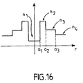
- the profile of the index of the fiber as a function of its radius r is represented in FIG. 4.
- this index n is linearly decreasing from a value n 1 up to a value n 2 reached for a radius a 1 , it has a constant value n 2 up to a radius a 2 , then takes a value n 3 constant between a 2 and a 3 , and then a constant value n 4 , index of the optical cladding.
- Such a fiber gives an elementary transfer function as shown in FIG. 5, the half-height width ⁇ o of which is greatly increased compared with that of a traditional fiber as represented in FIG. transfer function for a multiplexer as shown in Figure 6, also improved over that of the prior system shown in Figure 3.
- the indices will be such that n 1 - n 4 / n 4 , n 2 - n 4 / n 4 and n 3 - n 4 / n 4 are each less than 2.10 -3 .
- n 1 In another embodiment where the distribution of the index of the fiber is shown in FIG. 7, its value at the center n 1 is relatively small and it has this value up to a value a 1 of the radius, between the values a 1 and a 2 of the radius, the index is n 2 , the index is again n 1 between a 2 and a 3 , takes a value n 3 between a 3 and a 4 .
- the value n 1 of the index of the fiber in the center is relatively small and the index remains equal to n 1 up to a value a 1 of the radius.
- the index is n 2 , then it is equal to n 3 between a 2 and a 3 and n 4 for a value of the radius greater than a 3 .
- the values n 2 , n 3 and n 4 are in descending order.
- the different fibers can each be used in different multiplexer-demultiplexer devices.
- FIG 13 there is shown a network device 1, a input fiber 2 feeds the device into a multiplexed luminous flux and a output fiber comb 3 provides differentiated streams for each wavelengths.
- Fibers 3 are placed in the center of the network 1, itself approximately at the focus of a concave mirror 4.
- Space 5 between the network 1 and the mirror 4 can receive different components optics that allow, as needed, to improve the properties of the system.
- the dispersing element of the multiplexer-demultiplexer of the invention can also be an integrated optical network as shown in FIG. Figure 14.
- An input fiber 6 and an output fiber comb 7 are coupled integrated network 8 which is carried by a silicon substrate 9.
- fiber index profiles shown in FIGS. 4, 7 and 10 provide the transfer functions described above.
- the invention is further implemented in the device of multiplexer or integrated router n x n as shown in Figure 15, wherein input fibers 10 feed an input star coupler 12 which is connected to an output star coupler 13, itself associated with a set of output fibers 11, via an optical network integrated 14.
- fiber index profiles shown in FIGS. 4, 7 and 10 provide the transfer functions described above.
Claims (6)
- Faseroptischer Wellenlängen-Multiplexer-Demultiplexer mit einem Wellenlängen-Dispersionssystem, zumindest einer Eingangsfaser und zumindest einer Ausgangsfaser, die direkt an das Dispersionssystem angekoppelt sind, wobei die Fasern einen Kern und eine optische Umhüllung aufweisen,
dadurch gekennzeichnet, dass zumindest die eine der Eingangs- und Ausgangsfasern ein Indexprofil mit einem Zwischenring aufweist, der sich in der optischen Umhüllung befindet, wobei der optische Index vom Zwischenring größer als der optische Index von der optischen Umhüllung ist. - Multiplexer-Demultiplexer nach Anspruch 1, dadurch gekennzeichnet, dass die Ausgangsfasern ein Indexprofil aufweisen, der einen Isolationsring umfasst, der sich zwischen dem Kern und dem Zwischenring befindet, wobei der optische Index vom Isolationsring kleiner als der optische Index vom Zwischenring ist.
- Multiplexer-Demultiplexer nach einem der Ansprüche 1 oder 2, dadurch gekennzeichnet, dass die Indexschwankung vom Kern der Ausgangsfasern in Abhängigkeit von Strahl ab dem Zentrum linear abnehmend ist.
- Multiplexer-Demultiplexer nach einem der Ansprüche 1 oder 2, dadurch gekennzeichnet, dass die Indexschwankung vom Kern der Ausgangsfasern in Abhängigkeit vom Strahl ab dem Kern, erst linear zunehmend und anschließend linear abnehmend ist.
- Multiplexer-Demultiplexer nach einem der Ansprüche 1 oder 2, dadurch gekennzeichnet, dass die Indexschwankung vom Kern der Ausgangsfasern in Abhängigkeit vom Strahl ab dem Kern, erst konstant gleich einem Wert n1 ist, und anschließend konstant gleich einem Wert n2 > n1 ist, wobei die Schwankung somit einen Ring bildet.
- Multiplexer-Demultiplexer nach Anspruch 5, dadurch gekennzeichnet, dass die Indexschwankung vom Kern der Ausgangsfasern in Abhängigkeit vom Strahl ab dem Kern mehrere aufeinander folgende Ringe bildet.
Applications Claiming Priority (2)
| Application Number | Priority Date | Filing Date | Title |
|---|---|---|---|
| FR9703877 | 1997-03-28 | ||
| FR9703877A FR2761485B1 (fr) | 1997-03-28 | 1997-03-28 | Multiplexeur-demultiplexeur en longueur d'onde a fibres optiques |
Publications (2)
| Publication Number | Publication Date |
|---|---|
| EP0874252A1 EP0874252A1 (de) | 1998-10-28 |
| EP0874252B1 true EP0874252B1 (de) | 2005-10-05 |
Family
ID=9505328
Family Applications (1)
| Application Number | Title | Priority Date | Filing Date |
|---|---|---|---|
| EP98400638A Expired - Lifetime EP0874252B1 (de) | 1997-03-28 | 1998-03-18 | Faseroptischer Wellenlängen-Multiplexer-Demultiplexer |
Country Status (5)
| Country | Link |
|---|---|
| US (1) | US6157764A (de) |
| EP (1) | EP0874252B1 (de) |
| JP (1) | JP4082475B2 (de) |
| DE (1) | DE69831768T2 (de) |
| FR (1) | FR2761485B1 (de) |
Families Citing this family (2)
| Publication number | Priority date | Publication date | Assignee | Title |
|---|---|---|---|---|
| EP2083298B1 (de) | 2008-01-23 | 2017-05-10 | Yenista Optics | Optische Vorrichtung mit einem kompakten Dispersionssystem |
| CN117913000A (zh) * | 2016-06-30 | 2024-04-19 | 株式会社国际电气 | 衬底处理装置、半导体器件的制造方法及记录介质 |
Family Cites Families (7)
| Publication number | Priority date | Publication date | Assignee | Title |
|---|---|---|---|---|
| CA1038669A (en) * | 1975-09-22 | 1978-09-19 | Rama Iyengar | Optical fibre having low mode dispersion |
| FR2543768A1 (fr) * | 1983-03-31 | 1984-10-05 | Instruments Sa | Multiplexeur-demultiplexeur de longueurs d'onde, et procede de realisation d'un tel ensemble |
| US5278931A (en) * | 1992-12-31 | 1994-01-11 | Corning Incorporated | Low bend loss singlemode optical waveguide fiber |
| US5473719A (en) * | 1993-11-15 | 1995-12-05 | At&T Corp. | Optical dispersion compensator |
| US5559921A (en) * | 1994-06-24 | 1996-09-24 | Sumitomo Electric Industries, Ltd. | Single mode optical fiber |
| FR2724234B1 (fr) * | 1994-09-05 | 1997-01-03 | Alcatel Fibres Optiques | Fibre optique monomode a dispersion decalee |
| US5613027A (en) * | 1994-10-17 | 1997-03-18 | Corning Incorporated | Dispersion shifted optical waveguide fiber |
-
1997
- 1997-03-28 FR FR9703877A patent/FR2761485B1/fr not_active Expired - Fee Related
-
1998
- 1998-03-18 DE DE69831768T patent/DE69831768T2/de not_active Expired - Lifetime
- 1998-03-18 EP EP98400638A patent/EP0874252B1/de not_active Expired - Lifetime
- 1998-03-19 US US09/044,189 patent/US6157764A/en not_active Expired - Lifetime
- 1998-03-30 JP JP12384398A patent/JP4082475B2/ja not_active Expired - Lifetime
Also Published As
| Publication number | Publication date |
|---|---|
| DE69831768D1 (de) | 2006-02-16 |
| DE69831768T2 (de) | 2006-06-14 |
| JPH1123872A (ja) | 1999-01-29 |
| US6157764A (en) | 2000-12-05 |
| EP0874252A1 (de) | 1998-10-28 |
| JP4082475B2 (ja) | 2008-04-30 |
| FR2761485B1 (fr) | 1999-06-11 |
| FR2761485A1 (fr) | 1998-10-02 |
Similar Documents
| Publication | Publication Date | Title |
|---|---|---|
| EP0707223A1 (de) | Wellenlängenselektive optische Verzögerungsleitung | |
| FR2595477A1 (fr) | Circuit optique de demultiplexage/multiplexage | |
| FR2544883A1 (fr) | Multiplexeur/demultiplexeur optique | |
| EP0877266A1 (de) | Selektive optische Vorrichutng und Wellenlänge Multiplexer-Demultiplexer | |
| FR2779298A1 (fr) | Multiplexeur/demultiplexeur de longueur d'onde optique | |
| EP3491438B1 (de) | Multispektraler optischer koppler mit niedrigen empfangsverlusten | |
| EP1326104A1 (de) | Optischer Filter und Filterungsverfahren | |
| FR2655430A1 (fr) | Coupeur optique et systeme informatique a processeurs repartis. | |
| EP0916977A1 (de) | Demultiplexer mit quadratischer spektraler antwort | |
| FR2779535A1 (fr) | Multiplexeur compact | |
| EP0874252B1 (de) | Faseroptischer Wellenlängen-Multiplexer-Demultiplexer | |
| EP1377857A2 (de) | Hochauflösende integrierte optische spektrometer und zugehöriges herstellungsverfahren | |
| FR2742882A1 (fr) | Demultiplexeur de longueurs d'onde, realise en optique integree | |
| CA2160217C (fr) | Coupleur optique selectif en longueur d'onde | |
| CA2311157A1 (fr) | Multiplexeur/demultiplexeur optique a trois guides d'onde | |
| EP1433006B1 (de) | Optische komponente für die spektrale separation von licht verschiedener wellenlängen | |
| EP0984311A2 (de) | Optischer Multiplexer/Demultiplexer | |
| EP1867086B1 (de) | Optische übertragung zwischen einer ersten einheit und mehreren zweiten einheiten, die mittels eines passiven optischen zugangsnetzes verbunden sind | |
| EP2781957B1 (de) | Optische Filtervorrichtung mit Resonanzring | |
| EP0921422A1 (de) | Optische Komponente nach der Art eines Wellenleiter-Gitter- Spektrographes mit zentrierten Ausgangskanälen | |
| EP0921423A1 (de) | Optische Komponente mit Wellenleiter-Gitter-Spektrograph mit verbesserter Gittergeometrie | |
| FR2685786A1 (fr) | Coupleur de proximite en optique integree. | |
| EP0921424A1 (de) | Vorrichtung zum Austausch von optischen Signalen durch eine optische Faser | |
| FR2803046A1 (fr) | ROUTEUR OPTIQUE (n-p) A HAUTE DENSITE POUR RESEAUX DE FIBRES ET MULTIPLEXEUR-DEMULTIPLEXEUR OPTIQUE PERIODIQUE A HAUTE DENSITE POUR RESEAUX DE FIBRES INCORPORANT UN TEL ROUTEUR | |
| WO2005053194A1 (fr) | Composant optique incluant des micro-structures resonantes connectees en cascade |
Legal Events
| Date | Code | Title | Description |
|---|---|---|---|
| PUAI | Public reference made under article 153(3) epc to a published international application that has entered the european phase |
Free format text: ORIGINAL CODE: 0009012 |
|
| AK | Designated contracting states |
Kind code of ref document: A1 Designated state(s): DE FR GB |
|
| AX | Request for extension of the european patent |
Free format text: AL;LT;LV;MK;RO;SI |
|
| 17P | Request for examination filed |
Effective date: 19990428 |
|
| AKX | Designation fees paid |
Free format text: DE FR GB |
|
| RAP1 | Party data changed (applicant data changed or rights of an application transferred) |
Owner name: HIGHWAVE OPTICAL TECHNOLOGIES |
|
| RAP1 | Party data changed (applicant data changed or rights of an application transferred) |
Owner name: YENISTA OPTICS SA |
|
| GRAP | Despatch of communication of intention to grant a patent |
Free format text: ORIGINAL CODE: EPIDOSNIGR1 |
|
| GRAS | Grant fee paid |
Free format text: ORIGINAL CODE: EPIDOSNIGR3 |
|
| GRAA | (expected) grant |
Free format text: ORIGINAL CODE: 0009210 |
|
| AK | Designated contracting states |
Kind code of ref document: B1 Designated state(s): DE FR GB |
|
| REG | Reference to a national code |
Ref country code: GB Ref legal event code: FG4D Free format text: NOT ENGLISH |
|
| GBT | Gb: translation of ep patent filed (gb section 77(6)(a)/1977) |
Effective date: 20051116 |
|
| REF | Corresponds to: |
Ref document number: 69831768 Country of ref document: DE Date of ref document: 20060216 Kind code of ref document: P |
|
| PLBE | No opposition filed within time limit |
Free format text: ORIGINAL CODE: 0009261 |
|
| STAA | Information on the status of an ep patent application or granted ep patent |
Free format text: STATUS: NO OPPOSITION FILED WITHIN TIME LIMIT |
|
| 26N | No opposition filed |
Effective date: 20060706 |
|
| REG | Reference to a national code |
Ref country code: FR Ref legal event code: PLFP Year of fee payment: 19 |
|
| REG | Reference to a national code |
Ref country code: FR Ref legal event code: PLFP Year of fee payment: 20 |
|
| PGFP | Annual fee paid to national office [announced via postgrant information from national office to epo] |
Ref country code: DE Payment date: 20170322 Year of fee payment: 20 Ref country code: FR Payment date: 20170330 Year of fee payment: 20 |
|
| PGFP | Annual fee paid to national office [announced via postgrant information from national office to epo] |
Ref country code: GB Payment date: 20170322 Year of fee payment: 20 |
|
| REG | Reference to a national code |
Ref country code: DE Ref legal event code: R071 Ref document number: 69831768 Country of ref document: DE |
|
| REG | Reference to a national code |
Ref country code: GB Ref legal event code: PE20 Expiry date: 20180317 |
|
| PG25 | Lapsed in a contracting state [announced via postgrant information from national office to epo] |
Ref country code: GB Free format text: LAPSE BECAUSE OF EXPIRATION OF PROTECTION Effective date: 20180317 |