EP0874252B1 - Optical fibres wavelength multiplexer-demultiplexer - Google Patents
Optical fibres wavelength multiplexer-demultiplexer Download PDFInfo
- Publication number
- EP0874252B1 EP0874252B1 EP98400638A EP98400638A EP0874252B1 EP 0874252 B1 EP0874252 B1 EP 0874252B1 EP 98400638 A EP98400638 A EP 98400638A EP 98400638 A EP98400638 A EP 98400638A EP 0874252 B1 EP0874252 B1 EP 0874252B1
- Authority
- EP
- European Patent Office
- Prior art keywords
- index
- core
- multiplexer
- optical
- demultiplexer
- Prior art date
- Legal status (The legal status is an assumption and is not a legal conclusion. Google has not performed a legal analysis and makes no representation as to the accuracy of the status listed.)
- Expired - Lifetime
Links
- 230000003287 optical effect Effects 0.000 title claims description 19
- 239000000835 fiber Substances 0.000 claims description 57
- 239000013307 optical fiber Substances 0.000 claims description 17
- 230000003247 decreasing effect Effects 0.000 claims description 5
- 238000005253 cladding Methods 0.000 description 5
- 229920000297 Rayon Polymers 0.000 description 4
- 239000002964 rayon Substances 0.000 description 4
- 230000003595 spectral effect Effects 0.000 description 4
- XUIMIQQOPSSXEZ-UHFFFAOYSA-N Silicon Chemical compound [Si] XUIMIQQOPSSXEZ-UHFFFAOYSA-N 0.000 description 3
- 230000005540 biological transmission Effects 0.000 description 2
- 238000002955 isolation Methods 0.000 description 2
- 230000000644 propagated effect Effects 0.000 description 2
- 229910052710 silicon Inorganic materials 0.000 description 2
- 239000010703 silicon Substances 0.000 description 2
- 239000000758 substrate Substances 0.000 description 2
- 230000008878 coupling Effects 0.000 description 1
- 238000010168 coupling process Methods 0.000 description 1
- 238000005859 coupling reaction Methods 0.000 description 1
- 230000004907 flux Effects 0.000 description 1
- 238000009434 installation Methods 0.000 description 1
- 238000000926 separation method Methods 0.000 description 1
Images


Classifications
-
- G—PHYSICS
- G02—OPTICS
- G02B—OPTICAL ELEMENTS, SYSTEMS OR APPARATUS
- G02B6/00—Light guides; Structural details of arrangements comprising light guides and other optical elements, e.g. couplings
- G02B6/02—Optical fibres with cladding with or without a coating
- G02B6/028—Optical fibres with cladding with or without a coating with core or cladding having graded refractive index
- G02B6/0281—Graded index region forming part of the central core segment, e.g. alpha profile, triangular, trapezoidal core
-
- G—PHYSICS
- G02—OPTICS
- G02B—OPTICAL ELEMENTS, SYSTEMS OR APPARATUS
- G02B6/00—Light guides; Structural details of arrangements comprising light guides and other optical elements, e.g. couplings
- G02B6/02—Optical fibres with cladding with or without a coating
- G02B6/036—Optical fibres with cladding with or without a coating core or cladding comprising multiple layers
- G02B6/03605—Highest refractive index not on central axis
- G02B6/03611—Highest index adjacent to central axis region, e.g. annular core, coaxial ring, centreline depression affecting waveguiding
-
- G—PHYSICS
- G02—OPTICS
- G02B—OPTICAL ELEMENTS, SYSTEMS OR APPARATUS
- G02B6/00—Light guides; Structural details of arrangements comprising light guides and other optical elements, e.g. couplings
- G02B6/02—Optical fibres with cladding with or without a coating
- G02B6/036—Optical fibres with cladding with or without a coating core or cladding comprising multiple layers
- G02B6/03616—Optical fibres characterised both by the number of different refractive index layers around the central core segment, i.e. around the innermost high index core layer, and their relative refractive index difference
- G02B6/03638—Optical fibres characterised both by the number of different refractive index layers around the central core segment, i.e. around the innermost high index core layer, and their relative refractive index difference having 3 layers only
- G02B6/03644—Optical fibres characterised both by the number of different refractive index layers around the central core segment, i.e. around the innermost high index core layer, and their relative refractive index difference having 3 layers only arranged - + -
-
- G—PHYSICS
- G02—OPTICS
- G02B—OPTICAL ELEMENTS, SYSTEMS OR APPARATUS
- G02B6/00—Light guides; Structural details of arrangements comprising light guides and other optical elements, e.g. couplings
- G02B6/10—Light guides; Structural details of arrangements comprising light guides and other optical elements, e.g. couplings of the optical waveguide type
- G02B6/12—Light guides; Structural details of arrangements comprising light guides and other optical elements, e.g. couplings of the optical waveguide type of the integrated circuit kind
- G02B6/12007—Light guides; Structural details of arrangements comprising light guides and other optical elements, e.g. couplings of the optical waveguide type of the integrated circuit kind forming wavelength selective elements, e.g. multiplexer, demultiplexer
- G02B6/12009—Light guides; Structural details of arrangements comprising light guides and other optical elements, e.g. couplings of the optical waveguide type of the integrated circuit kind forming wavelength selective elements, e.g. multiplexer, demultiplexer comprising arrayed waveguide grating [AWG] devices, i.e. with a phased array of waveguides
-
- G—PHYSICS
- G02—OPTICS
- G02B—OPTICAL ELEMENTS, SYSTEMS OR APPARATUS
- G02B6/00—Light guides; Structural details of arrangements comprising light guides and other optical elements, e.g. couplings
- G02B6/24—Coupling light guides
- G02B6/26—Optical coupling means
- G02B6/28—Optical coupling means having data bus means, i.e. plural waveguides interconnected and providing an inherently bidirectional system by mixing and splitting signals
- G02B6/293—Optical coupling means having data bus means, i.e. plural waveguides interconnected and providing an inherently bidirectional system by mixing and splitting signals with wavelength selective means
- G02B6/29304—Optical coupling means having data bus means, i.e. plural waveguides interconnected and providing an inherently bidirectional system by mixing and splitting signals with wavelength selective means operating by diffraction, e.g. grating
- G02B6/29316—Light guides comprising a diffractive element, e.g. grating in or on the light guide such that diffracted light is confined in the light guide
- G02B6/29325—Light guides comprising a diffractive element, e.g. grating in or on the light guide such that diffracted light is confined in the light guide of the slab or planar or plate like form, i.e. confinement in a single transverse dimension only
- G02B6/29326—Diffractive elements having focusing properties, e.g. curved gratings
-
- G—PHYSICS
- G02—OPTICS
- G02B—OPTICAL ELEMENTS, SYSTEMS OR APPARATUS
- G02B6/00—Light guides; Structural details of arrangements comprising light guides and other optical elements, e.g. couplings
- G02B6/24—Coupling light guides
- G02B6/26—Optical coupling means
- G02B6/28—Optical coupling means having data bus means, i.e. plural waveguides interconnected and providing an inherently bidirectional system by mixing and splitting signals
- G02B6/293—Optical coupling means having data bus means, i.e. plural waveguides interconnected and providing an inherently bidirectional system by mixing and splitting signals with wavelength selective means
- G02B6/29304—Optical coupling means having data bus means, i.e. plural waveguides interconnected and providing an inherently bidirectional system by mixing and splitting signals with wavelength selective means operating by diffraction, e.g. grating
- G02B6/29316—Light guides comprising a diffractive element, e.g. grating in or on the light guide such that diffracted light is confined in the light guide
- G02B6/29325—Light guides comprising a diffractive element, e.g. grating in or on the light guide such that diffracted light is confined in the light guide of the slab or planar or plate like form, i.e. confinement in a single transverse dimension only
- G02B6/29328—Diffractive elements operating in reflection
-
- G—PHYSICS
- G02—OPTICS
- G02B—OPTICAL ELEMENTS, SYSTEMS OR APPARATUS
- G02B6/00—Light guides; Structural details of arrangements comprising light guides and other optical elements, e.g. couplings
- G02B6/24—Coupling light guides
- G02B6/26—Optical coupling means
- G02B6/28—Optical coupling means having data bus means, i.e. plural waveguides interconnected and providing an inherently bidirectional system by mixing and splitting signals
- G02B6/293—Optical coupling means having data bus means, i.e. plural waveguides interconnected and providing an inherently bidirectional system by mixing and splitting signals with wavelength selective means
- G02B6/29379—Optical coupling means having data bus means, i.e. plural waveguides interconnected and providing an inherently bidirectional system by mixing and splitting signals with wavelength selective means characterised by the function or use of the complete device
- G02B6/2938—Optical coupling means having data bus means, i.e. plural waveguides interconnected and providing an inherently bidirectional system by mixing and splitting signals with wavelength selective means characterised by the function or use of the complete device for multiplexing or demultiplexing, i.e. combining or separating wavelengths, e.g. 1xN, NxM
Definitions
- the present invention relates to a multiplexer-demultiplexer in fiber-optic wavelength, which can be used as component in fiber teletransmission installations optics.
- optical fiber multiplexer-demultiplexer devices in which the input and output light waves are propagated by optical fibers.
- the invention also relates to fiber optic routers in which a variable number of input streams, each having a particular wavelength propagated by optical fibers spatially distinct, are addressed to a possible number different from output fibers.
- a dispersive system realizes the coupling, for a given wavelength between an output fiber and an input fiber.
- Multiplexer-demultiplexers or high-performance routers must simultaneously enable the exploitation of a large number of channels, each of these channels, centered on a wavelength ⁇ , must have a spectral width ⁇ as large as possible, while avoiding any crosstalk.
- crosstalk when part of the energy of a channel is partially mixed with the energy of an adjacent channel. He is well known that crosstalk disrupts communications and that excessive crosstalk rates are in practice unusable.
- the device of the invention will be qualified multiplexer-demultiplexer, it being understood that it can be a multiplexer, a demultiplexer or a router.
- the object of the invention is therefore to propose a multiplexer-demultiplexer which offers improved properties and while retaining a good separation of the channels, improves the spectral width of each of them.
- optical fiber input or output possibly input and output, having index variations that make it possible to obtain the widening of the spectral width sought.
- the invention relates to a multiplexer-demultiplexer in fiber-optic wavelength having a wavelength dispersive system at the least one input fiber and at least one output fiber directly coupled to the dispersive system, the fibers of output having a core and an optical cladding.
- the output and / or input fibers have an index profile with a ring intermediate, located in the optical cladding, optical index of said intermediate ring being greater than the optical index of the sheath optical.
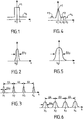
- Figures 1 to 3 are intended to show the operation of transmission devices with a dispersive element of the prior art.
- Single-mode fibers having an index distribution from their center O where the core of the fiber has an index n 1 and the optical cladding of the fiber has an index n 0 .
- the fibers having such an index profile give a wavelength transmission function between an input fiber and an output fiber separated by a dispersive element, as represented on FIG. Figure 2 having approximately a Gaussian shape centered on a wavelength ⁇ o and width halfway ⁇ o .
- the bandwidth of the entire device In the case of a multiplexer or demultiplexer, several fibers, eg output, being associated with an input fiber, the bandwidth of the entire device, shown in Figure 3, consists of a plurality of elementary bandwidths such as those shown in FIG. 2.
- the distance between the different central wavelengths ⁇ 1 , ⁇ 2 ,..., ⁇ n is limited by the possibilities of mechanical approximation of the cores of the adjacent fibers. this limitation being due to the mechanical bulk of the fiber composed of its core, its optical cladding and its mechanical sheath.
- the profile of the index of the fiber as a function of its radius r is represented in FIG. 4.
- this index n is linearly decreasing from a value n 1 up to a value n 2 reached for a radius a 1 , it has a constant value n 2 up to a radius a 2 , then takes a value n 3 constant between a 2 and a 3 , and then a constant value n 4 , index of the optical cladding.
- Such a fiber gives an elementary transfer function as shown in FIG. 5, the half-height width ⁇ o of which is greatly increased compared with that of a traditional fiber as represented in FIG. transfer function for a multiplexer as shown in Figure 6, also improved over that of the prior system shown in Figure 3.
- the indices will be such that n 1 - n 4 / n 4 , n 2 - n 4 / n 4 and n 3 - n 4 / n 4 are each less than 2.10 -3 .
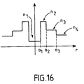
- n 1 In another embodiment where the distribution of the index of the fiber is shown in FIG. 7, its value at the center n 1 is relatively small and it has this value up to a value a 1 of the radius, between the values a 1 and a 2 of the radius, the index is n 2 , the index is again n 1 between a 2 and a 3 , takes a value n 3 between a 3 and a 4 .
- the value n 1 of the index of the fiber in the center is relatively small and the index remains equal to n 1 up to a value a 1 of the radius.
- the index is n 2 , then it is equal to n 3 between a 2 and a 3 and n 4 for a value of the radius greater than a 3 .
- the values n 2 , n 3 and n 4 are in descending order.
- the different fibers can each be used in different multiplexer-demultiplexer devices.
- FIG 13 there is shown a network device 1, a input fiber 2 feeds the device into a multiplexed luminous flux and a output fiber comb 3 provides differentiated streams for each wavelengths.
- Fibers 3 are placed in the center of the network 1, itself approximately at the focus of a concave mirror 4.
- Space 5 between the network 1 and the mirror 4 can receive different components optics that allow, as needed, to improve the properties of the system.
- the dispersing element of the multiplexer-demultiplexer of the invention can also be an integrated optical network as shown in FIG. Figure 14.
- An input fiber 6 and an output fiber comb 7 are coupled integrated network 8 which is carried by a silicon substrate 9.
- fiber index profiles shown in FIGS. 4, 7 and 10 provide the transfer functions described above.
- the invention is further implemented in the device of multiplexer or integrated router n x n as shown in Figure 15, wherein input fibers 10 feed an input star coupler 12 which is connected to an output star coupler 13, itself associated with a set of output fibers 11, via an optical network integrated 14.
- fiber index profiles shown in FIGS. 4, 7 and 10 provide the transfer functions described above.
Description
La présente invention concerne un multiplexeur-démultiplexeur en longueur d'onde à fibres optiques, susceptible d'être utilisé comme composant dans les installations de télétransmissions par fibres optiques.The present invention relates to a multiplexer-demultiplexer in fiber-optic wavelength, which can be used as component in fiber teletransmission installations optics.
On connaít déjà de tels multiplexeurs-démultiplexeurs qui ont été décrits, puis progressivement perfectionnés, en particulier dans les brevets français FR-2.543.768, FR-2.519.148, FR-2.479.981, FR-2.496.260 et dans le brevet européen EP-0.196.963.We already know such multiplexers-demultiplexers that have been described, then progressively improved, particularly in French patents FR-2,543,768, FR-2,519,148, FR-2,479,981, FR-2.496.260 and in European Patent EP-0.196.963.
On entend ici par multiplexeur-démultiplexeur à fibres optiques, des dispositifs dans lesquels les ondes lumineuses d'entrée et de sortie sont propagées par des fibres optiques.Here is meant by optical fiber multiplexer-demultiplexer, devices in which the input and output light waves are propagated by optical fibers.
L'invention concerne également les routeurs à fibres optiques dans lesquels un nombre variable de flux d'entrée, ayant chacun une longueur d'onde particulière, propagés par des fibres optiques spatialement distinctes, sont adressés sur un nombre éventuellement différent de fibres de sorties.The invention also relates to fiber optic routers in which a variable number of input streams, each having a particular wavelength propagated by optical fibers spatially distinct, are addressed to a possible number different from output fibers.
Dans ces différents dispositifs, un système dispersif réalise le couplage, pour une longueur d'onde donnée entre une fibre de sortie et une fibre d'entrée.In these different devices, a dispersive system realizes the coupling, for a given wavelength between an output fiber and an input fiber.
On définit ainsi un canal qui a bien entendu une certaine largeur spectrale Δλ.This defines a channel that has of course a certain width spectral Δλ.
Les multiplexeurs-démultiplexeurs ou routeurs performants doivent simultanément permettre l'exploitation d'un grand nombre de canaux, chacun de ces canaux, centrés sur une longueur d'onde λ, doit avoir une largeur spectrale Δλ aussi grande que possible, tout en évitant une quelconque diaphonie.Multiplexer-demultiplexers or high-performance routers must simultaneously enable the exploitation of a large number of channels, each of these channels, centered on a wavelength λ, must have a spectral width Δλ as large as possible, while avoiding any crosstalk.
Il y a diaphonie lorsqu'une partie de l'énergie d'un canal est partiellement mélangée à l'énergie d'un canal adjacent. Il est bien connu que la diaphonie perturbe les communications et que les dispositifs présentant un taux de diaphonie excessif sont en pratique inutilisables.There is crosstalk when part of the energy of a channel is partially mixed with the energy of an adjacent channel. He is well known that crosstalk disrupts communications and that excessive crosstalk rates are in practice unusable.
Pour simplifier la description, le dispositif de l'invention sera qualifié de multiplexeur-démultiplexeur, étant bien entendu qu'il peut s'agir d'un multiplexeur, d'un démultiplexeur ou d'un routeur.To simplify the description, the device of the invention will be qualified multiplexer-demultiplexer, it being understood that it can be a multiplexer, a demultiplexer or a router.
Le but de l'invention est donc de proposer un multiplexeur-démultiplexeur qui offre des propriétés améliorées et tout en conservant une bonne séparation des canaux, améliore la largeur spectrale de chacun d'eux.The object of the invention is therefore to propose a multiplexer-demultiplexer which offers improved properties and while retaining a good separation of the channels, improves the spectral width of each of them.
Pour atteindre ce but, on a proposé, selon l'invention, de mettre en oeuvre des fibres optiques d'entrée ou de sortie, éventuellement d'entrée et de sortie, ayant des variations d'indice qui permettent d'obtenir l'élargissement de la largeur spectrale recherchée.To achieve this goal, it has been proposed, according to the invention, to optical fiber input or output, possibly input and output, having index variations that make it possible to obtain the widening of the spectral width sought.
A cet effet, l'invention concerne un multiplexeur-démultiplexeur en longueur d'onde à fibres optiques comportant un système dispersif en longueur d'onde, au moins une fibre d'entrée et au moins une fibre de sortie directement couplées au système dispersif, les fibres de sortie ayant un coeur et une gaine optique.For this purpose, the invention relates to a multiplexer-demultiplexer in fiber-optic wavelength having a wavelength dispersive system at the least one input fiber and at least one output fiber directly coupled to the dispersive system, the fibers of output having a core and an optical cladding.
Selon l'invention, les fibres de sortie et/ou d'entrée ont un profil d'indice avec un anneau intermédiaire, situé dans la gaine optique, l'indice optique dudit anneau intermédiaire étant supérieur à l'indice optique de la gaine optique.According to the invention, the output and / or input fibers have an index profile with a ring intermediate, located in the optical cladding, optical index of said intermediate ring being greater than the optical index of the sheath optical.
Selon différents modes de réalisation présentant chacun leurs avantages particuliers :
- lesdites fibres ont un profil d'indice comportant un anneau d'isolement situé entre le coeur et l'anneau intermédiaire, l'indice optique dudit anneau d'isolement étant inférieur à celui de l'anneau intermédiaire,
- la variation de l'indice du coeur desdites fibres, en fonction du rayon, est linéairement décroissante à partir du centre,
- la variation de l'indice du coeur desdites fibres, en fonction du rayon, à partir du coeur, est d'abord linéairement croissante, puis linéairement décroissante,
- la variation de l'indice du coeur desdites fibres, en fonction du rayon, à partir du coeur, est d'abord constante, égale à une valeur n1, puis constante à une valeur n2 > n1, ladite variation formant ainsi un anneau,
- la variation de l'indice du coeur desdites fibres, en fonction du rayon, à partir du coeur, forme plusieurs anneaux successifs.
- said fibers have an index profile comprising an isolation ring located between the core and the intermediate ring, the optical index of said isolation ring being lower than that of the intermediate ring,
- the variation of the index of the core of said fibers, as a function of the radius, is linearly decreasing from the center,
- the variation of the core index of said fibers, as a function of the radius, from the core, is first linearly increasing, then linearly decreasing,
- the variation of the index of the core of said fibers, as a function of the radius, from the core, is firstly constant, equal to a value n 1 , then constant to a value n 2 > n 1 , said variation thus forming a ring,
- the variation of the index of the core of said fibers, as a function of the radius, from the heart, forms several successive rings.
L'invention sera décrite en détail en référence aux dessins annexés dans lesquels :
- la Figure 1 représente le profil d'indice d'une fibre monomode utilisée dans des multiplexeurs en longueur d'onde à réseau selon l'art antérieur;
- la Figure 2 représente le profil d'indice d'un canal obtenu selon l'art antérieur, avec une fibre optique de la Figure 1;
- la Figure 3 représente la fonction de transfert d'un multiplexeur de l'art antérieur, réalisée avec des fibres optiques de la Figure 1;
- la Figure 4 représente un premier exemple de profil d'indice d'une fibre optique monomode utilisée selon l'invention;
- la Figure 5 représente le profil d'indice d'un canal obtenu selon l'invention, avec une fibre optique de la Figure 4;
- la Figure 6 représente la fonction de transfert d'un multiplexeur de l'invention, réalisée avec des fibres optiques de la Figure 4;
- la Figure 7 représente un deuxième exemple de profil d'indice d'une fibre optique monomode utilisée selon l'invention;
- la Figure 8 représente le profil d'indice d'un canal obtenu selon l'invention, avec une fibre optique de la Figure 7;
- la Figure 9 représente la fonction de transfert d'un multiplexeur de l'invention, réalisée avec des fibres optiques de la Figure 7;
- la Figure 10 représente un troisième exemple de profil d'indice d'une fibre optique monomode utilisée selon l'invention;
- la Figure 11 représente le profil d'indice d'un canal obtenu selon l'invention, avec une fibre optique de la Figure 10;
- la Figure 12 représente la fonction de transfert d'un multiplexeur de l'invention, réalisée avec des fibres optiques de la Figure 10;
- la Figure 13 est un exemple de démultiplexeur à réseau classique mettant en oeuvre l'invention;
- la Figure 14 est un exemple de multiplexeur à réseau intégré sur un substrat silicium mettant en oeuvre l'invention;
- la Figure 15 est un exemple de multiplexeur intégré mettant en oeuvre l'invention;
- la Figure 16 représente un quatrième exemple de profil d'indice d'une fibre optique monomode utilisée selon l'invention.
- Figure 1 shows the index profile of a single mode fiber used in network wavelength multiplexers according to the prior art;
- FIG. 2 represents the index profile of a channel obtained according to the prior art, with an optical fiber of FIG. 1;
- Figure 3 shows the transfer function of a multiplexer of the prior art, made with optical fibers of Figure 1;
- FIG. 4 represents a first example of an index profile of a monomode optical fiber used according to the invention;
- Figure 5 shows the index profile of a channel obtained according to the invention, with an optical fiber of Figure 4;
- Figure 6 shows the transfer function of a multiplexer of the invention, made with optical fibers of Figure 4;
- FIG. 7 represents a second example of an index profile of a monomode optical fiber used according to the invention;
- Figure 8 shows the index profile of a channel obtained according to the invention, with an optical fiber of Figure 7;
- Figure 9 shows the transfer function of a multiplexer of the invention, made with optical fibers of Figure 7;
- FIG. 10 represents a third example of an index profile of a monomode optical fiber used according to the invention;
- Figure 11 shows the index profile of a channel obtained according to the invention, with an optical fiber of Figure 10;
- Figure 12 shows the transfer function of a multiplexer of the invention, made with optical fibers of Figure 10;
- Fig. 13 is an example of a conventional network demultiplexer embodying the invention;
- Figure 14 is an example of an integrated network multiplexer on a silicon substrate embodying the invention;
- Figure 15 is an example of an integrated multiplexer embodying the invention;
- FIG. 16 represents a fourth example of an index profile of a monomode optical fiber used according to the invention.
Les Figures 1 à 3 sont destinées à présenter le fonctionnement de dispositifs de transmission avec un élément dispersif de l'art antérieur.Figures 1 to 3 are intended to show the operation of transmission devices with a dispersive element of the prior art.
Les fibres monomodes ayant une répartition d'indice à partir de leur centre O où le coeur de la fibre a un indice n1 et la gaine optique (ou cladding) de la fibre a un indice n0. Single-mode fibers having an index distribution from their center O where the core of the fiber has an index n 1 and the optical cladding of the fiber has an index n 0 .
On sait que les fibres ayant un tel profil d'indice, représenté sur la Figure 1, donnent une fonction de transmission en longueur d'onde entre une fibre d'entrée et une fibre de sortie séparées par un élément dispersif, tel que représenté sur la Figure 2 ayant approximativement une forme de gaussienne centrée sur une longueur d'onde λo et de largeur à mi-hauteur Δλo.It is known that the fibers having such an index profile, shown in FIG. 1, give a wavelength transmission function between an input fiber and an output fiber separated by a dispersive element, as represented on FIG. Figure 2 having approximately a Gaussian shape centered on a wavelength λ o and width halfway Δλ o .
Dans le cas d'un multiplexeur ou d'un démultiplexeur, plusieurs fibres, par exemple de sortie, étant associées à une fibre d'entrée, la bande passante de l'ensemble du dispositif, représentée sur la Figure 3, est constituée d'une pluralité de bandes passantes élémentaires telles que celles représentées sur la Figure 2. La distance entre les différentes longueurs d'onde centrales λ1, λ2,...,λn est limitée par les possibilités de rapprochement mécanique des coeurs des fibres adjacentes, cette limitation étant due à l'encombrement mécanique de la fibre composée de son coeur, de sa gaine optique (cladding) et de sa gaine mécanique.In the case of a multiplexer or demultiplexer, several fibers, eg output, being associated with an input fiber, the bandwidth of the entire device, shown in Figure 3, consists of a plurality of elementary bandwidths such as those shown in FIG. 2. The distance between the different central wavelengths λ 1 , λ 2 ,..., λ n is limited by the possibilities of mechanical approximation of the cores of the adjacent fibers. this limitation being due to the mechanical bulk of the fiber composed of its core, its optical cladding and its mechanical sheath.
Dans un premier exemple de réalisation de l'invention, le profil de l'indice de la fibre en fonction de son rayon r est représenté sur la Figure 4. Partant du centre O, cet indice n est linéairement décroissant à partir d'une valeur n1 jusqu'à une valeur n2 atteinte pour un rayon a1, il a une valeur constante n2 jusqu'à un rayon a2, puis prend une valeur n3 constante entre a2 et a3, et ensuite une valeur constante n4, indice de la gaine optique.In a first exemplary embodiment of the invention, the profile of the index of the fiber as a function of its radius r is represented in FIG. 4. Starting from the center O, this index n is linearly decreasing from a value n 1 up to a value n 2 reached for a radius a 1 , it has a constant value n 2 up to a radius a 2 , then takes a value n 3 constant between a 2 and a 3 , and then a constant value n 4 , index of the optical cladding.
Une telle fibre donne une fonction de transfert élémentaire telle que représentée sur la Figure 5, dont la largeur à mi-hauteur Δλo est largement augmentée par rapport à celle d'une fibre traditionnelle telle que représentée sur la Figure 2. Il en découle une fonction de transfert pour un multiplexeur tel que représenté sur la Figure 6, également améliorée par rapport à celle du système antérieur représenté sur la Figure 3.Such a fiber gives an elementary transfer function as shown in FIG. 5, the half-height width Δλ o of which is greatly increased compared with that of a traditional fiber as represented in FIG. transfer function for a multiplexer as shown in Figure 6, also improved over that of the prior system shown in Figure 3.
Les valeurs de ces paramètres sont avantageusement les
suivantes :
En règle générale, dans ce mode de réalisation, les indices seront tels que n 1 - n 4 / n 4, n 2-n 4 / n 4 et n 3-n 4 / n 4 soient chacun inférieur à 2.10-3.As a general rule, in this embodiment, the indices will be such that n 1 - n 4 / n 4 , n 2 - n 4 / n 4 and n 3 - n 4 / n 4 are each less than 2.10 -3 .
Dans un autre mode de réalisation où la répartition de l'indice de la fibre est représentée sur la Figure 7, sa valeur au centre n1 est relativement faible et il a cette valeur jusqu'à une valeur a1 du rayon, entre les valeurs a1 et a2 du rayon, l'indice est n2, l'indice est de nouveau n1 entre a2 et a3, prend une valeur n3 entre a3 et a4.In another embodiment where the distribution of the index of the fiber is shown in FIG. 7, its value at the center n 1 is relatively small and it has this value up to a value a 1 of the radius, between the values a 1 and a 2 of the radius, the index is n 2 , the index is again n 1 between a 2 and a 3 , takes a value n 3 between a 3 and a 4 .
Les valeurs de ces paramètres sont avantageusement les
suivantes :
Selon un troisième mode de réalisation représenté sur la Figure 10, toujours en partant du centre, l'indice a d'abord une valeur n1 au centre, progressivement linéairement croissante jusqu'à une valeur n2 atteinte pour le rayon r = a1, l'indice est alors égal à une valeur n3, puis l'anneau intermédiaire constitué entre les rayons r = a2 et r = a3 définit un anneau dans lequel l'indice de la fibre est n4, l'indice de la gaine optique est égal à n3.According to a third embodiment shown in FIG. 10, still starting from the center, the index first has a value n 1 at the center, progressively linearly increasing until a value n 2 reached for the radius r = a 1 , the index is then equal to a value n 3 , then the intermediate ring formed between the radii r = a 2 and r = a 3 defines a ring in which the index of the fiber is n 4 , the index of the optical sheath is equal to n 3 .
Les valeurs de ces paramètres sont avantageusement les
suivantes:
Selon un quatrième mode de réalisation représenté sur la Figure 16, la valeur n1 de l'indice de la fibre au centre est relativement faible et l'indice reste égal à n1 jusqu'à une valeur a1 du rayon. Entre les valeurs a1 et a2 du rayon, l'indice vaut n2, puis il est égal à n3 entre a2 et a3 et n4 pour une valeur du rayon supérieure à a3. Les valeurs n2, n3 et n4 sont en ordre décroissant.According to a fourth embodiment shown in FIG. 16, the value n 1 of the index of the fiber in the center is relatively small and the index remains equal to n 1 up to a value a 1 of the radius. Between the values a 1 and a 2 of the radius, the index is n 2 , then it is equal to n 3 between a 2 and a 3 and n 4 for a value of the radius greater than a 3 . The values n 2 , n 3 and n 4 are in descending order.
Les différentes fibres peuvent chacune être mises en oeuvre dans différents dispositifs multiplexeurs-démultiplexeurs.The different fibers can each be used in different multiplexer-demultiplexer devices.
Sur la Figure 13, on a représenté un dispositif à réseau 1, une
fibre d'entrée 2 alimente le dispositif en un flux lumineux multiplexé et un
peigne de fibres de sortie 3 fournit des flux différenciés pour chacune
des longueurs d'onde.In Figure 13, there is shown a
Les extrémités de ces fibres 3 sont placées au centre du réseau 1,
lui-même approximativement au foyer d'un miroir concave 4. L'espace 5
entre le réseau 1 et le miroir 4 peut recevoir différents composants
optiques permettant, en fonction des besoins, d'améliorer les propriétés
du système.The ends of these
Dans un tel dispositif, des profils de chacune des fibres du peigne
de fibres 3 correspondant à ceux décrits plus haut et représentés sur les
Figures 4, 7 et 10, donnent à ce démultiplexeur les fonctions de transfert
représentées aux Figures 6, 9 et 12.In such a device, profiles of each of the fibers of the comb
of
L'élément disperseur du multiplexeur-démultiplexeur de l'invention peut également être un réseau optique intégré tel que représenté sur la Figure 14.The dispersing element of the multiplexer-demultiplexer of the invention can also be an integrated optical network as shown in FIG. Figure 14.
Une fibre d'entrée 6 et un peigne de fibres de sortie 7 sont couplés
au réseau intégré 8 qui est porté par un substrat silicium 9.An input fiber 6 and an output fiber comb 7 are coupled
integrated network 8 which is carried by a
Ici encore, les profils d'indice des fibres représentées aux Figures 4, 7 et 10 fournissent les fonctions de transfert décrites plus haut.Here again, the fiber index profiles shown in FIGS. 4, 7 and 10 provide the transfer functions described above.
L'invention est encore mise en oeuvre dans le dispositif de
multiplexeur ou routeur intégré n x n tel que représenté sur la Figure 15,
dans lequel des fibres d'entrée 10 alimentent un coupleur étoile d'entrée
12 qui est relié à un coupleur étoile de sortie 13, lui-même associé à un
ensemble de fibres de sortie 11, par l'intermédiaire d'un réseau optique
intégré 14.The invention is further implemented in the device of
multiplexer or integrated router n x n as shown in Figure 15,
wherein
Ici encore, les profils d'indice des fibres représentées aux Figures 4, 7 et 10 fournissent les fonctions de transfert décrites plus haut.Here again, the fiber index profiles shown in FIGS. 4, 7 and 10 provide the transfer functions described above.
De manière générale, différents profils d'indice de fibre peuvent permettre la mise en oeuvre de l'invention. La théorie de la propagation des ondes lumineuses dans les fibres monomodes, présentée par J.P. LAUDE dans son ouvrage "Le multiplexage de longueur d'onde", Masson éditeur, 1992 (ISBN 2-225-82755-9), donne les références de plusieurs articles scientifiques de différents auteurs qui permettent pour un profil donné, de calculer le rayon équivalent de la fibre. Plus le rapport rayon équivalent sur rayon réel est élevé, meilleures sont les performances des multiplexeurs-démultiplexeurs.In general, different fiber index profiles can be allow the implementation of the invention. The theory of propagation light waves in single-mode fibers presented by J.P. LAUDE in his book "Wavelength multiplexing", Masson publisher, 1992 (ISBN 2-225-82755-9), gives the references of several scientific articles from different authors that allow for a given profile, to calculate the equivalent radius of the fiber. More report equivalent radius on real radius is high, the better the multiplexer-demultiplexer performance.
Claims (6)
- Optical fibre wavelength multiplexer-demultiplexer comprising a wavelength dispersing system, at least one input fibre and at least one output fibre coupled directly to the dispersing system, said fibres having a core and an optical sheath,
characterised in that at least one of the input and output fibres has an index profile with an intermediate ring situated in the optical sheath, the optical index of said intermediate ring being greater than the optical index of the optical sheath. - Multiplexer-demultiplexer according to claim 1, characterised in that the output fibres have an index profile comprising an insulating ring situated between the core and the intermediate ring, the optical index of said insulating ring being less than that of the intermediate ring.
- Multiplexer-demultiplexer according to one of claims 1 or 2, characterised in that the variation in the index of the core of the output fibres, as a function of the radius, is decreasing linearly from the centre.
- Multiplexer-demultiplexer according to one of claims 1 or 2, characterised in that the variation in the index of the core of the output fibres, as a function of the radius, from the core, is firstly increasing linearly then decreasing linearly.
- Multiplexer-demultiplexer according to one of claims 1 or 2, characterised in that the variation in the index of the core of the output fibres, as a function of the radius, from the core, is firstly constant, equal to a value n1, then constant at a value n2 > n1, said variation thus forming a ring.
- Multiplexer-demultiplexer according to claim 5, characterised in that the variation in the index of the core of the output fibres, as a function of the radius, from the core, forms a plurality of successive rings.
Applications Claiming Priority (2)
| Application Number | Priority Date | Filing Date | Title |
|---|---|---|---|
| FR9703877A FR2761485B1 (en) | 1997-03-28 | 1997-03-28 | OPTICAL FIBER WAVELENGTH MULTIPLEXER-DEMULTIPLEXER |
| FR9703877 | 1997-03-28 |
Publications (2)
| Publication Number | Publication Date |
|---|---|
| EP0874252A1 EP0874252A1 (en) | 1998-10-28 |
| EP0874252B1 true EP0874252B1 (en) | 2005-10-05 |
Family
ID=9505328
Family Applications (1)
| Application Number | Title | Priority Date | Filing Date |
|---|---|---|---|
| EP98400638A Expired - Lifetime EP0874252B1 (en) | 1997-03-28 | 1998-03-18 | Optical fibres wavelength multiplexer-demultiplexer |
Country Status (5)
| Country | Link |
|---|---|
| US (1) | US6157764A (en) |
| EP (1) | EP0874252B1 (en) |
| JP (1) | JP4082475B2 (en) |
| DE (1) | DE69831768T2 (en) |
| FR (1) | FR2761485B1 (en) |
Families Citing this family (2)
| Publication number | Priority date | Publication date | Assignee | Title |
|---|---|---|---|---|
| EP2083298B1 (en) | 2008-01-23 | 2017-05-10 | Yenista Optics | Optical device comprising a compact dispersing system |
| KR20240017095A (en) * | 2016-06-30 | 2024-02-06 | 가부시키가이샤 코쿠사이 엘렉트릭 | Substrate processing device, method for manufacturing semiconductor device, and recording medium |
Family Cites Families (7)
| Publication number | Priority date | Publication date | Assignee | Title |
|---|---|---|---|---|
| CA1038669A (en) * | 1975-09-22 | 1978-09-19 | Rama Iyengar | Optical fibre having low mode dispersion |
| FR2543768A1 (en) * | 1983-03-31 | 1984-10-05 | Instruments Sa | WAVE LENGTH MULTIPLEXER-DEMULTIPLEXER AND METHOD OF MAKING SAME |
| US5278931A (en) * | 1992-12-31 | 1994-01-11 | Corning Incorporated | Low bend loss singlemode optical waveguide fiber |
| US5473719A (en) * | 1993-11-15 | 1995-12-05 | At&T Corp. | Optical dispersion compensator |
| US5559921A (en) * | 1994-06-24 | 1996-09-24 | Sumitomo Electric Industries, Ltd. | Single mode optical fiber |
| FR2724234B1 (en) * | 1994-09-05 | 1997-01-03 | Alcatel Fibres Optiques | SINGLE-MODE OPTICAL FIBER WITH OFFSET DISPERSION |
| US5613027A (en) * | 1994-10-17 | 1997-03-18 | Corning Incorporated | Dispersion shifted optical waveguide fiber |
-
1997
- 1997-03-28 FR FR9703877A patent/FR2761485B1/en not_active Expired - Fee Related
-
1998
- 1998-03-18 DE DE69831768T patent/DE69831768T2/en not_active Expired - Lifetime
- 1998-03-18 EP EP98400638A patent/EP0874252B1/en not_active Expired - Lifetime
- 1998-03-19 US US09/044,189 patent/US6157764A/en not_active Expired - Lifetime
- 1998-03-30 JP JP12384398A patent/JP4082475B2/en not_active Expired - Lifetime
Also Published As
| Publication number | Publication date |
|---|---|
| US6157764A (en) | 2000-12-05 |
| DE69831768D1 (en) | 2006-02-16 |
| FR2761485B1 (en) | 1999-06-11 |
| JP4082475B2 (en) | 2008-04-30 |
| EP0874252A1 (en) | 1998-10-28 |
| JPH1123872A (en) | 1999-01-29 |
| DE69831768T2 (en) | 2006-06-14 |
| FR2761485A1 (en) | 1998-10-02 |
Similar Documents
| Publication | Publication Date | Title |
|---|---|---|
| FR2595477A1 (en) | OPTICAL DEMULTIPLEXING / MULTIPLEXING CIRCUIT | |
| FR2544883A1 (en) | OPTICAL MULTIPLEXER / DEMULTIPLEXER | |
| EP0877266A1 (en) | Selective optical device and wavelenght multiplexer-demultiplexer | |
| FR2779298A1 (en) | Optical wavelength multiplexer or demultiplexer | |
| EP3491438B1 (en) | Multi-spectral optical coupler with low receive losses | |
| EP1326104A1 (en) | Optical filter and method of filtering | |
| FR2655430A1 (en) | OPTICAL CUTTER AND COMPUTER SYSTEM WITH DISTRIBUTED PROCESSORS. | |
| EP0916977A1 (en) | Square spectral response demultiplexer | |
| FR2779535A1 (en) | COMPACT MULTIPLEXER | |
| EP0874252B1 (en) | Optical fibres wavelength multiplexer-demultiplexer | |
| EP1377857A2 (en) | Integrated high spectral resolution optical spectrometer and method for making same | |
| FR2742882A1 (en) | WAVELENGTH DEMULTIPLEXER, REALIZED IN INTEGRATED OPTICS | |
| CA2160217C (en) | Wavelength selective optical coupler | |
| CA2311157A1 (en) | Multiplexer/demultiplexer with three waveguides | |
| EP1433006B1 (en) | Optical component with spectral separation | |
| EP0984311A2 (en) | Optical multiplexor/demultiplexor | |
| EP1867086B1 (en) | Optical transmission between a first unit and a plurality of second units interconnected by means of a passive optical access network | |
| EP2781957B1 (en) | Optical filtering device with resonator ring | |
| EP0921422A1 (en) | Optical component of the type of a waveguide grating spectrograph with centered output channels | |
| EP0921423A1 (en) | Optical component with waveguide grating spectrograph with improved grating geometry | |
| FR2685786A1 (en) | INTEGRATED OPTICAL PROXIMITY COUPLER. | |
| Wang et al. | Low-crosstalk 1× 40 100 GHz spacing Cascaded Planar Echelle Gratings for Mux/Demux on 3-μm Silicon platform | |
| EP0921424A1 (en) | Arrangement for exchanging optical signals through an optical fibre | |
| FR2803046A1 (en) | High density fibre optical router multiplex/demultiplexer system, has multiple fibre input/outputs/single dispersive connected and input spacing small wavelength /output spaced geometrically | |
| WO2005053194A1 (en) | Optical component comprising cascade-connected resonant microstructures |
Legal Events
| Date | Code | Title | Description |
|---|---|---|---|
| PUAI | Public reference made under article 153(3) epc to a published international application that has entered the european phase |
Free format text: ORIGINAL CODE: 0009012 |
|
| AK | Designated contracting states |
Kind code of ref document: A1 Designated state(s): DE FR GB |
|
| AX | Request for extension of the european patent |
Free format text: AL;LT;LV;MK;RO;SI |
|
| 17P | Request for examination filed |
Effective date: 19990428 |
|
| AKX | Designation fees paid |
Free format text: DE FR GB |
|
| RAP1 | Party data changed (applicant data changed or rights of an application transferred) |
Owner name: HIGHWAVE OPTICAL TECHNOLOGIES |
|
| RAP1 | Party data changed (applicant data changed or rights of an application transferred) |
Owner name: YENISTA OPTICS SA |
|
| GRAP | Despatch of communication of intention to grant a patent |
Free format text: ORIGINAL CODE: EPIDOSNIGR1 |
|
| GRAS | Grant fee paid |
Free format text: ORIGINAL CODE: EPIDOSNIGR3 |
|
| GRAA | (expected) grant |
Free format text: ORIGINAL CODE: 0009210 |
|
| AK | Designated contracting states |
Kind code of ref document: B1 Designated state(s): DE FR GB |
|
| REG | Reference to a national code |
Ref country code: GB Ref legal event code: FG4D Free format text: NOT ENGLISH |
|
| GBT | Gb: translation of ep patent filed (gb section 77(6)(a)/1977) |
Effective date: 20051116 |
|
| REF | Corresponds to: |
Ref document number: 69831768 Country of ref document: DE Date of ref document: 20060216 Kind code of ref document: P |
|
| PLBE | No opposition filed within time limit |
Free format text: ORIGINAL CODE: 0009261 |
|
| STAA | Information on the status of an ep patent application or granted ep patent |
Free format text: STATUS: NO OPPOSITION FILED WITHIN TIME LIMIT |
|
| 26N | No opposition filed |
Effective date: 20060706 |
|
| REG | Reference to a national code |
Ref country code: FR Ref legal event code: PLFP Year of fee payment: 19 |
|
| REG | Reference to a national code |
Ref country code: FR Ref legal event code: PLFP Year of fee payment: 20 |
|
| PGFP | Annual fee paid to national office [announced via postgrant information from national office to epo] |
Ref country code: DE Payment date: 20170322 Year of fee payment: 20 Ref country code: FR Payment date: 20170330 Year of fee payment: 20 |
|
| PGFP | Annual fee paid to national office [announced via postgrant information from national office to epo] |
Ref country code: GB Payment date: 20170322 Year of fee payment: 20 |
|
| REG | Reference to a national code |
Ref country code: DE Ref legal event code: R071 Ref document number: 69831768 Country of ref document: DE |
|
| REG | Reference to a national code |
Ref country code: GB Ref legal event code: PE20 Expiry date: 20180317 |
|
| PG25 | Lapsed in a contracting state [announced via postgrant information from national office to epo] |
Ref country code: GB Free format text: LAPSE BECAUSE OF EXPIRATION OF PROTECTION Effective date: 20180317 |