EP0872178A1 - Grid-shaped fence particularly but not exclusively for forbidding access to railway tracks - Google Patents
Grid-shaped fence particularly but not exclusively for forbidding access to railway tracks Download PDFInfo
- Publication number
- EP0872178A1 EP0872178A1 EP98400945A EP98400945A EP0872178A1 EP 0872178 A1 EP0872178 A1 EP 0872178A1 EP 98400945 A EP98400945 A EP 98400945A EP 98400945 A EP98400945 A EP 98400945A EP 0872178 A1 EP0872178 A1 EP 0872178A1
- Authority
- EP
- European Patent Office
- Prior art keywords
- fact
- fence
- ground
- fasteners
- attachment
- Prior art date
- Legal status (The legal status is an assumption and is not a legal conclusion. Google has not performed a legal analysis and makes no representation as to the accuracy of the status listed.)
- Withdrawn
Links
Images


Classifications
-
- E—FIXED CONSTRUCTIONS
- E04—BUILDING
- E04H—BUILDINGS OR LIKE STRUCTURES FOR PARTICULAR PURPOSES; SWIMMING OR SPLASH BATHS OR POOLS; MASTS; FENCING; TENTS OR CANOPIES, IN GENERAL
- E04H17/00—Fencing, e.g. fences, enclosures, corrals
- E04H17/02—Wire fencing, e.g. made of wire mesh
- E04H17/06—Parts for wire fences
- E04H17/08—Anchoring means therefor, e.g. specially-shaped parts entering the ground; Struts or the like
-
- A—HUMAN NECESSITIES
- A01—AGRICULTURE; FORESTRY; ANIMAL HUSBANDRY; HUNTING; TRAPPING; FISHING
- A01K—ANIMAL HUSBANDRY; CARE OF BIRDS, FISHES, INSECTS; FISHING; REARING OR BREEDING ANIMALS, NOT OTHERWISE PROVIDED FOR; NEW BREEDS OF ANIMALS
- A01K3/00—Pasturing equipment, e.g. tethering devices; Grids for preventing cattle from straying; Electrified wire fencing
-
- E—FIXED CONSTRUCTIONS
- E04—BUILDING
- E04H—BUILDINGS OR LIKE STRUCTURES FOR PARTICULAR PURPOSES; SWIMMING OR SPLASH BATHS OR POOLS; MASTS; FENCING; TENTS OR CANOPIES, IN GENERAL
- E04H17/00—Fencing, e.g. fences, enclosures, corrals
- E04H17/02—Wire fencing, e.g. made of wire mesh
- E04H17/06—Parts for wire fences
Definitions
- the present invention relates to wire fences and more particularly but not exclusively those used for prohibit access to railways.
- Such fences include mesh fences rectangular for example, formed by the union of wires generally horizontal and vertical, welded in their intertwining.
- the fence can thus be damaged to the point of becoming passable.
- the main object of the present invention is to render a chainlink fence that cannot be crossed by animals such as boars.
- wire fence clip characterized in that it has at one end a means of attachment such as a hook for example and by the fact that it is provided along its length and on the same side with directed claws toward said end.
- the fastener is constituted by assembling a main iron bent upward at its lower end to form said hook and a plurality of short irons, welded obliquely to the body of the iron main, to form said claws.
- the number of claws is greater than or equal to three.
- the fastener comprises five claws, the first four starting from said hook being arranged with a constant spacing, and the last with greater spacing.
- the invention also relates to a fixing device for wire fencing, characterized in that it includes fasteners as mentioned above and anchoring devices in the ground to be connected to the fasteners.
- This device may also include shaped inserts elongated, subject to the grid in the direction of its length.
- Each insert is constituted for example by a round iron, of which the diameter is preferably greater than or equal to 12 mm.
- Another subject of the invention is a chainlink fence, characterized by the fact that it has fasteners such as defined above, hung from above on the wires of the mesh and connected to anchor points in the ground.
- anchor points consist of anchoring devices which are driven into these recesses, the insertion of the anchoring devices into the ground exerting a downward pull on the fasteners.
- the fasteners prevent the lifting of the mesh by the animals, and at the crossing of the fence.
- the wire fence 1 partially shown on the Figure 1, includes a grid formed by the meeting of a set of 2 metallic wires parallel to the ground and a set of wires metallic 3 perpendicular to the first, assembled by a arc welding at their intersections 4.
- the wires 2 are supported by posts implanted by example along a railroad track and not shown.
- the wires 3 are preferably, as shown, arranged with a constant spacing between them, equal to 20 cm for example.
- the wires 2 are preferably, as shown, arranged with increasing spacing from bottom to top.
- the spacing between the first four wires 2 in starting from the bottom is 4 cm for example and then goes to 6 cm by. example for the next two wires, to reach 10 then 20 cm for example at the top of the grid, not shown.
- the wire 2 located at the bottom of the mesh is at ground level.
- the invention applies to any fence whatever whatever the number and the spacing of the wires constituting the mesh, or the shape of the mesh, which can be diamond-shaped example.
- rows of inserts 5 are subject to the base of the mesh.
- Each row is made up of a set of inserts 5 arranged in the extension of one another, each of the inserts 5 of a row being woven between 3 threads and resting on the same wire 2, as shown more particularly in FIG. 2.
- each insert 5 is easy, inserting it parallel to the wires 2 in the mesh of the mesh, on either side of at least three wires 3.
- Fasteners 7 comprising claws 8 coming to hang on the inserts 5 are hung on anchoring devices 6 sunk into the ground.
- FIG. 3 shows an anchoring device 6 isolation.
- Each anchoring device 6 comprises a metal tube 9 to insert into the ground, provided at its upper end with a tab 10 angled at right angles, the upright 11 of which is drilled to serve for the attachment of a fastener 7.
- Each fastener 7 has a curved lower end upwards to form a hook 12, intended to hang on a anchoring device 6.
- This hook 12 can optionally be folded down towards the interior after its insertion into the hole in a tab 10, as shown in dashed lines in Figure 2, to be rendered harder to pick up.
- FIG. 5 shows separately a fastener 7 comprising three claws 8, the spacing of which corresponds to that of first three wires 2 of the fence, counted from the bottom.
- FIG. 6 shows a fastener 17 comprising two claws 8 more than the previous one.
- the distance between the claw 8 located at the upper end of the tie and the one located immediately below is greater than the spacing between the lower claws, this to take into account the fact that the wires 2 are arranged with increasing spacing on the fence.
- the fasteners 7 and 17 shown in Figures 5 and 6 are made from a C shaped iron to make the hook 12 and the claw 8 adjacent.
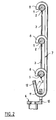
- FIG. 7 shows a fastener 27 conforming to a variant.
- This fastener 27 is made from a main iron 20, round, curved upwards at its lower end to form the hook 12.
- a plurality of irons 21 of round section and of a lesser diameter than the main iron, and short in length are welded on the straight body of the main iron 20.
- the irons 21 are straight and are welded obliquely to a end on the body of the main iron 20, all being substantially parallel, directed downward diametrically opposite the hook 12.
- the irons 21 constitute claws intended to come in plug on wires 2.
- the first iron 21 in starting from the bottom is welded to the body of the main iron 20 substantially at the base of the hook 12, that the following three irons 21 are arranged with a constant spacing between them while the last iron 21 is welded near the upper end of the main iron 20, the spacing between the latter iron 21 and the preceding being greater than that between the other irons 21.
- the clip is zinc plated to resist corrosion.
- the fasteners according to the invention can be used without provide the wire fence with inserts 5, as illustrated on the figure 8.
- Recesses 16 are dug in the ground at locations where the anchoring devices will be inserted 6.
- the hooks 12 of the fasteners are engaged in the holes tabs 10, then the anchoring devices 6 are pushed in completely in the ground, and then exert on the fasteners a pulling down, which keeps the claws of the fasteners on the wires 2 (or on the inserts 5 when these are present) as well as maintaining the attachment of hooks 12 on the legs 10.
- the mesh reinforced by the device according to the invention proves particularly resistant to the attacks of wild boars in particular, because the fasteners oppose the lifting of the base of the roasting by the snout of the animal.
Abstract
Description
La présente invention concerne les clôtures grillagées et plus particulièrement mais non exclusivement celles utilisées pour interdire l'accès aux voies ferrées.The present invention relates to wire fences and more particularly but not exclusively those used for prohibit access to railways.
De telles clôtures comportent des grillages à mailles rectangulaires par exemple, constitués par la réunion de fils généralement horizontaux et verticaux, soudés en leurs entrecroisements.Such fences include mesh fences rectangular for example, formed by the union of wires generally horizontal and vertical, welded in their intertwining.
Lorsqu'un animal d'un poids important tel qu'un sanglier frappe avec son groin de façon répétée la base du grillage pour tenter de la soulever et de passer dessous, les fils horizontaux peuvent rompre ou se désolidariser des fils verticaux.When a large animal such as a wild boar repeatedly strikes the base of the fence with his snout try to lift it and pass under it, the horizontal wires can break or break off vertical wires.
La clôture peut ainsi être endommagée au point de devenir franchissable.The fence can thus be damaged to the point of becoming passable.
Les animaux, qui traversent alors les voies, risquent d'être percutés par les trains.Animals, which then cross the tracks, risk being hit by trains.
On a cherché à renforcer les clôtures grillagées existantes en plaquant sur ces dernières un grillage supplémentaire de moindre hauteur mais partiellement enfoui dans le sol.We tried to reinforce the existing wire fences by placing on the latter an additional grid of lesser tall but partially buried in the ground.
Une telle solution, qui exige la réalisation d'une tranchée, est coûteuse à mettre en oeuvre.Such a solution, which requires the construction of a trench, is expensive to implement.
La présente invention vise principalement à rendre une clôture grillagée infranchissable par des animaux tels que des sangliers.The main object of the present invention is to render a chainlink fence that cannot be crossed by animals such as boars.
Elle y parvient grâce à une attache pour clôture grillagée, caractérisée par le fait qu'elle comporte à une extrémité un moyen d'accrochage tel qu'un crochet par exemple et par le fait qu'elle est munie sur sa longueur et sur un même côté de griffes dirigées vers ladite extrémité.It does this with a wire fence clip, characterized in that it has at one end a means of attachment such as a hook for example and by the fact that it is provided along its length and on the same side with directed claws toward said end.
Dans une réalisation particulière, l'attache est constituée par l'assemblage d'un fer principal recourbé vers le haut à son extrémité inférieure pour former ledit crochet et d'une pluralité de fers de courte longueur, soudés obliquement sur le corps du fer principal, pour former lesdites griffes. In a particular embodiment, the fastener is constituted by assembling a main iron bent upward at its lower end to form said hook and a plurality of short irons, welded obliquely to the body of the iron main, to form said claws.
De préférence, le nombre de griffes est supérieur ou égal à trois.Preferably, the number of claws is greater than or equal to three.
De préférence encore, l'attache comporte cinq griffes, les quatre premières en partant dudit crochet étant disposées avec un écartement constant, et la dernière avec un écartement supérieur.More preferably, the fastener comprises five claws, the first four starting from said hook being arranged with a constant spacing, and the last with greater spacing.
L'invention a encore pour objet un dispositif de fixation pour clôture grillagée, caractérisé par le fait qu'il comporte des attaches telles que précitées et des dispositifs d'ancrage dans le sol à relier aux attaches.The invention also relates to a fixing device for wire fencing, characterized in that it includes fasteners as mentioned above and anchoring devices in the ground to be connected to the fasteners.
Ce dispositif peut comporter en outre des inserts de forme allongée, assujettis au grillage dans le sens de sa longueur. Chaque insert est constitué par exemple par un fer rond, dont le diamètre est de préférence supérieur ou égal à 12 mm.This device may also include shaped inserts elongated, subject to the grid in the direction of its length. Each insert is constituted for example by a round iron, of which the diameter is preferably greater than or equal to 12 mm.
L'invention a encore pour objet une clôture grillagée, caractérisée par le fait qu'elle comporte des attaches telles que définies plus haut, accrochées par le dessus sur les fils du grillage et reliées à des points d'ancrage dans le sol.Another subject of the invention is a chainlink fence, characterized by the fact that it has fasteners such as defined above, hung from above on the wires of the mesh and connected to anchor points in the ground.
L'invention a encore pour objet un procédé pour rendre infranchissable par un animal tel qu'un sanglier une clôture grillagée, caractérisé par le fait qu'il comporte les étapes consistant à :
- mettre en place des attaches telles que définies plus haut, ces attaches venant s'accrocher sur le grillage de la clôture,
- réaliser des points d'ancrage dans le sol le long du grillage, chaque attache étant reliée à un point d'ancrage dans le sol.
- install fasteners as defined above, these fasteners coming to hang on the fence mesh,
- make anchor points in the ground along the fence, each fastener being connected to an anchor point in the ground.
De préférence, l'on réalise au niveau de chaque point d'ancrage un léger renfoncement dans le sol et les points d'ancrage sont constitués par des dispositifs d'ancrage qui sont enfoncés dans ces renfoncements, l'enfoncement des dispositifs d'ancrage dans le sol exerçant une traction dirigée vers le bas sur les attaches.Preferably, we realize at each point anchor a slight recess in the ground and anchor points consist of anchoring devices which are driven into these recesses, the insertion of the anchoring devices into the ground exerting a downward pull on the fasteners.
Les attaches s'opposent au soulèvement du grillage par les animaux, et au franchissement de la clôture.The fasteners prevent the lifting of the mesh by the animals, and at the crossing of the fence.
D'autres caractéristiques et avantages de la présente invention apparaítront à la lecture de la description détaillée qui va suivre, et à l'examen du dessin annexé sur lequel :
- la figure 1 est une vue schématique, partielle et en perspective, d'une clôture grillagée équipée d'attaches conformément à un premier exemple de mise en oeuvre de l'invention,
- la figure 2 est une coupe schématique montrant trois inserts reliés par une attache commune à un dispositif d'ancrage dans le sol,
- la figure 3 représente isolément ce dispositif d'ancrage dans le sol,
- la figure 4 illustre l'utilisation dos à dos de deux dispositifs d'ancrage dans le sol,
- les figures 5 à 7 représentent respectivement trois exemples de réalisation d'attaches selon l'invention, et
- la figure 8 est une vue schématique partielle et en perspective, d'une clôture grillagée équipée d'attaches conformément à un deuxième exemple de mise en oeuvre de l'invention.
- FIG. 1 is a schematic, partial and perspective view of a chain-link fence fitted with fasteners in accordance with a first example of implementation of the invention,
- FIG. 2 is a schematic section showing three inserts connected by a common attachment to an anchoring device in the ground,
- FIG. 3 represents in isolation this anchoring device in the ground,
- FIG. 4 illustrates the back-to-back use of two anchoring devices in the ground,
- FIGS. 5 to 7 respectively represent three exemplary embodiments of fasteners according to the invention, and
- Figure 8 is a partial schematic perspective view of a chainlink fence equipped with fasteners according to a second example of implementation of the invention.
La clôture grillagée 1, partiellement représentée sur la
figure 1, comporte un grillage formé par la réunion d'un ensemble de
fils métalliques 2 parallèles au sol et d'un ensemble de fils
métalliques 3 perpendiculaires aux premiers, assemblés par une
soudure à l'arc en leurs entrecroisements 4.The
Les fils 2 sont supportés par des poteaux implantés par
exemple le long d'une voie ferrée et non représentés.The
Les fils 3 sont de préférence, comme représenté, disposés
avec un écartement constant entre eux, égal à 20 cm par exemple.The
Les fils 2 sont de préférence, comme représenté, disposés
avec un écartement croissant de bas en haut.The
Ainsi, l'écartement entre les quatre premiers fils 2 en
partant du bas est de 4 cm par exemple et passe ensuite à 6 cm par.
exemple pour les deux fils suivants, pour atteindre 10 puis 20 cm
par exemple en haut du grillage, non représenté.Thus, the spacing between the first four
De préférence, le fil 2 situé le plus en bas du grillage est
au niveau de la surface du sol.Preferably, the
Bien entendu, l'invention s'applique à toute clôture quels que soient le nombre et l'écartement des fils constituant le grillage, ou la forme des mailles, qui peut être en losange par exemple. Of course, the invention applies to any fence whatever whatever the number and the spacing of the wires constituting the mesh, or the shape of the mesh, which can be diamond-shaped example.
Dans un premier exemple de mise en oeuvre de l'invention, des
rangées d'inserts 5, constitués chacun par un fer rond de 1 m de
long environ et de 12 mm de diamètre environ, sont assujetties à la
base du grillage.In a first example of implementation of the invention,
rows of
Chaque rangée est constituée par un ensemble d'inserts 5
disposés dans le prolongement l'un de l'autre, chacun des inserts 5
d'une rangée étant tissé entre des fils 3 et reposant sur un même
fil 2, comme représenté plus particulièrement sur la figure 2.Each row is made up of a set of
La mise en place de chaque insert 5 se fait aisément, en
l'insérant parallèlement aux fils 2 dans les mailles du grillage, de
part et d'autre d'au moins trois fils 3.The insertion of each
Des attaches 7 comportant des griffes 8 venant s'accrocher
sur les inserts 5 sont accrochées sur des dispositifs d'ancrage 6
enfoncés dans le sol.
On a représenté sur la figure 3 un dispositif d'ancrage 6
isolément.FIG. 3 shows an
Dans l'exemple de réalisation décrit, on utilise des dispositifs d'ancrage commercialisés sous la dénomination "FENOX" par les Etablissements FAYNOT à Montherme dans les Ardennes.In the embodiment described, we use anchoring devices sold under the name "FENOX" by the FAYNOT Establishments in Montherme in the Ardennes.
Chaque dispositif d'ancrage 6 comporte un tube métallique 9 à
insérer dans le sol, muni à son extrémité supérieure d'une patte 10
coudée en équerre, dont le montant 11 est percé pour servir à
l'accrochage d'une attache 7.Each
Un pieu métallique 13, muni à son extrémité inférieure de
fils 14, est descendu dans le tube 9 fiché en terre.A
Au cours de l'enfoncement du pieu 13, les fils 14 sortent du
tube 9 et s'écartent dans le sol, rendant ainsi difficile son
extraction.During the driving of the
On peut utiliser si nécessaire, pour un meilleur ancrage dans
le sol et comme illustré sur la figure 4, deux dispositifs d'ancrage
6 disposés dos à dos de manière à présenter une ouverture commune 15
pour l'accrochage d'une attache 7.It can be used if necessary, for better anchoring in
the ground and as illustrated in FIG. 4, two
Chaque attache 7 comporte une extrémité inférieure recourbée
vers le haut pour former un crochet 12, destiné à s'accrocher sur un
dispositif d'ancrage 6.Each
Ce crochet 12 peut éventuellement être rabattu vers
l'intérieur après son insertion dans le perçage d'une patte 10,
comme illustré en traits mixtes sur la figure 2, pour être rendu
plus difficile à décrocher.This
On a représenté isolément sur la figure 5 une attache 7
comportant trois griffes 8, dont l'écartement correspond à celui des
trois premiers fils 2 du grillage, comptés en partant du bas.FIG. 5 shows separately a
On peut réaliser, sans sortir du cadre de la présente invention, des attaches avec un nombre quelconque de griffes, selon le degré de renforcement souhaité de la clôture.We can realize, without departing from the framework of this invention, fasteners with any number of claws, according to the desired degree of reinforcement of the fence.
A titre d'exemple, on a représenté sur la figure 6 une
attache 17 comportant deux griffes 8 de plus que la précédente.By way of example, FIG. 6 shows a
Comme on pourra le constater à l'examen de cette figure,
l'écartement entre la griffe 8 située à l'extrémité supérieure de
l'attache et celle située immédiatement en dessous est supérieur à
l'écartement entre les griffes inférieures, ceci pour tenir compte
du fait que les fils 2 sont disposés avec un écartement croissant
sur le grillage.As you will see from examining this figure,
the distance between the
Les attaches 7 et 17 représentées sur les figures 5 et 6 sont
réalisées en partant d'un fer conformé en C pour réaliser le crochet
12 et la griffe 8 adjacente.The
Ensuite, selon le nombre de griffes 8 supplémentaires que doit comporter l'attache, on vient souder en les superposant dans le sens de la hauteur des fers conformés chacun en crosse, et présentant chacun la longueur adaptée à l'écartement entre les fils 2 correspondants du grillage.Then, depending on the number of additional 8 claws that must include the clip, we just weld by superimposing them in the direction of the height of the irons each shaped into a stick, and each having the length adapted to the spacing between the 2 wires corresponding to the wire mesh.
On a représenté sur la figure 7 une attache 27 conforme à une
variante de réalisation.FIG. 7 shows a
Cette attache 27 est réalisée à partir d'un fer principal 20,
de section ronde, recourbé vers le haut à son extrémité inférieure
pour former le crochet 12.This
Une pluralité de fers 21 de section ronde et d'un moindre
diamètre que le fer principal, et de courte longueur sont soudés sur
le corps rectiligne du fer principal 20.A plurality of
Les fers 21 sont droits et sont soudés obliquement à une
extrémité sur le corps du fer principal 20, étant tous sensiblement
parallèles, dirigés vers le bas diamétralement à l'opposé du crochet
12. The
Les fers 21 constituent des griffes destinées à venir en
prise sur les fils 2.The
On remarquera sur la figure 7 que le premier fer 21 en
partant du bas est soudé sur le corps du fer principal 20
sensiblement à la base du crochet 12, que les trois fers 21 suivants
sont disposés avec un écartement constant entre eux tandis que le
dernier fer 21 est soudé à proximité de l'extrémité supérieure du
fer principal 20, l'écartement entre ce dernier fer 21 et le
précédent étant supérieur à celui entre les autres fers 21.Note in Figure 7 that the
L'attache est zinguée de manière à résister à la corrosion.The clip is zinc plated to resist corrosion.
Les attaches conformes à l'invention peuvent s'utiliser sans
munir la clôture grillagée d'inserts 5, comme illustré sur la
figure 8.The fasteners according to the invention can be used without
provide the wire fence with
Sur cette figure, on a représenté deux attaches 27 dont les
griffes viennent en prise par le dessus directement sur les fils 2
du grillage.In this figure, two
D'une manière générale, on choisira la densité linéaire des
dispositifs d'ancrage 6 et des attaches, ainsi que le nombre de
rangées d'inserts 5 le cas échéant, en fonction notamment de la
nature du grillage, de celle du terrain et de sa pente.In general, we will choose the linear density of
6 anchors and fasteners, as well as the number of
rows of
On préférera ainsi augmenter la densité des attaches et des
dispositifs d'ancrage 6 lorsque le grillage se situe dans un creux,
et que la tension des fils 2 tend à éloigner sa base du sol.We will thus prefer to increase the density of the fasteners and
Si l'on utilise des inserts, on commence par munir le
grillage de ces inserts 5 que l'on fait reposer sur les fils 2, puis
les attaches sont accrochées sur les inserts 5.If you use inserts, you start by providing the
roasting of these
Si l'on n'utilise pas d'inserts 5, les attaches sont
accrochées directement sur les fils 2.If no
Des renfoncements 16 sont creusés dans le sol aux
emplacements où seront enfoncés les dispositifs d'ancrage 6.
Ensuite, les dispositifs d'ancrage 6 sont enfoncés
partiellement dans le sol.Then the
Les crochets 12 des attaches sont engagés dans les perçages
des pattes 10, puis les dispositifs d'ancrage 6 sont enfoncés
complètement dans le sol, et exercent alors sur les attaches une
traction vers le bas, ce qui assure le maintien en prise des
griffes des attaches sur les fils 2 (ou sur les inserts 5 lorsque
ceux-ci sont présents) ainsi que le maintien de l'accrochage des
crochets 12 sur les pattes 10.The
Lorsque le grillage a des mailles en forme de losange et que l'on utilise des inserts 5, ceux-ci reposent sur les entrecroisements des fils.When the mesh has diamond-shaped meshes and inserts 5 are used, these are based on intertwining of wires.
Le grillage renforcé par le dispositif selon l'invention s'avère particulièrement résistant aux assauts des sangliers notamment, car les attaches s'opposent au soulèvement de la base du grillage par le groin de l'animal.The mesh reinforced by the device according to the invention proves particularly resistant to the attacks of wild boars in particular, because the fasteners oppose the lifting of the base of the roasting by the snout of the animal.
D'autre part, lorsque l'on utilise en outre des inserts 5,
les efforts exercés localement sur le grillage se trouvent repris
par une surface relativement importante du grillage, de sorte
qu'aucun fil ou soudure ne rompt.On the other hand, when we also use
Bien entendu, l'invention n'est pas limitée aux exemples de réalisation qui viennent d'être décrits.Of course, the invention is not limited to the examples of realization which have just been described.
On peut notamment varier la forme des attaches et le cas échéant celle des inserts.We can in particular vary the shape of the fasteners and the case that of the inserts.
L'utilisation de fers ronds pour réaliser les inserts est toutefois avantageuse car ces derniers sont alors peu coûteux et relativement aisés à installer sur le grillage.The use of round irons to make the inserts is however advantageous because the latter are then inexpensive and relatively easy to install on the fence.
On peut bien entendu utiliser d'autres dispositifs d'ancrage que ceux décrits, ainsi que des attaches réalisées autrement.It is of course possible to use other anchoring devices than those described, as well as attachments made otherwise.
Claims (11)
Applications Claiming Priority (2)
| Application Number | Priority Date | Filing Date | Title |
|---|---|---|---|
| FR9704745 | 1997-04-17 | ||
| FR9704745A FR2762344B1 (en) | 1997-04-17 | 1997-04-17 | MESH FENCING TO PROHIBIT ACCESS TO RAILWAYS IN PARTICULAR |
Publications (1)
| Publication Number | Publication Date |
|---|---|
| EP0872178A1 true EP0872178A1 (en) | 1998-10-21 |
Family
ID=9506030
Family Applications (1)
| Application Number | Title | Priority Date | Filing Date |
|---|---|---|---|
| EP98400945A Withdrawn EP0872178A1 (en) | 1997-04-17 | 1998-04-16 | Grid-shaped fence particularly but not exclusively for forbidding access to railway tracks |
Country Status (2)
| Country | Link |
|---|---|
| EP (1) | EP0872178A1 (en) |
| FR (1) | FR2762344B1 (en) |
Cited By (3)
| Publication number | Priority date | Publication date | Assignee | Title |
|---|---|---|---|---|
| FR2904648A1 (en) * | 2006-08-01 | 2008-02-08 | Profilafroid Sa | Grid anchorage hinge for netted fence, has upper part with pawls that are anchored with grid, and lower part with pawls that are intended to be inserted in ground since latter pawls contribute to increase resistance at wrenching of hinge |
| JP2018139523A (en) * | 2017-02-27 | 2018-09-13 | エコ ジャパン株式会社 | Animal invasion prevention fence and installation method |
| US10472851B1 (en) * | 2003-04-23 | 2019-11-12 | Robert J. Brislin | Fence anchor device |
Citations (6)
| Publication number | Priority date | Publication date | Assignee | Title |
|---|---|---|---|---|
| US1672787A (en) * | 1926-01-18 | 1928-06-05 | Warren A Smith | Anchoring device |
| US1764284A (en) * | 1929-11-14 | 1930-06-17 | John T Barton | Fence |
| FR1362177A (en) * | 1963-06-26 | 1964-05-29 | Improvement in fence posts | |
| GB1566494A (en) * | 1978-03-02 | 1980-04-30 | Chicken & Rabbit Netting Ltd | Rabbit netting |
| GB2170239A (en) * | 1985-01-29 | 1986-07-30 | Fencing Supplies Limited | Security fencing |
| FR2590113A1 (en) * | 1985-11-15 | 1987-05-22 | Trefilunion | Trellis equipped with defensive means intended for producing fencing |
-
1997
- 1997-04-17 FR FR9704745A patent/FR2762344B1/en not_active Expired - Fee Related
-
1998
- 1998-04-16 EP EP98400945A patent/EP0872178A1/en not_active Withdrawn
Patent Citations (6)
| Publication number | Priority date | Publication date | Assignee | Title |
|---|---|---|---|---|
| US1672787A (en) * | 1926-01-18 | 1928-06-05 | Warren A Smith | Anchoring device |
| US1764284A (en) * | 1929-11-14 | 1930-06-17 | John T Barton | Fence |
| FR1362177A (en) * | 1963-06-26 | 1964-05-29 | Improvement in fence posts | |
| GB1566494A (en) * | 1978-03-02 | 1980-04-30 | Chicken & Rabbit Netting Ltd | Rabbit netting |
| GB2170239A (en) * | 1985-01-29 | 1986-07-30 | Fencing Supplies Limited | Security fencing |
| FR2590113A1 (en) * | 1985-11-15 | 1987-05-22 | Trefilunion | Trellis equipped with defensive means intended for producing fencing |
Cited By (3)
| Publication number | Priority date | Publication date | Assignee | Title |
|---|---|---|---|---|
| US10472851B1 (en) * | 2003-04-23 | 2019-11-12 | Robert J. Brislin | Fence anchor device |
| FR2904648A1 (en) * | 2006-08-01 | 2008-02-08 | Profilafroid Sa | Grid anchorage hinge for netted fence, has upper part with pawls that are anchored with grid, and lower part with pawls that are intended to be inserted in ground since latter pawls contribute to increase resistance at wrenching of hinge |
| JP2018139523A (en) * | 2017-02-27 | 2018-09-13 | エコ ジャパン株式会社 | Animal invasion prevention fence and installation method |
Also Published As
| Publication number | Publication date |
|---|---|
| FR2762344B1 (en) | 1999-07-30 |
| FR2762344A1 (en) | 1998-10-23 |
Similar Documents
| Publication | Publication Date | Title |
|---|---|---|
| US4787601A (en) | Decorative border fence system | |
| JPH06501860A (en) | Fixing device for use on sandy beaches or sandy soils | |
| LU85061A1 (en) | DEVICE AND METHOD FOR CONNECTING RETAINING AND CONSOLIDATION RATES | |
| EP0117781B1 (en) | Device to palisade, post and tie for such a device | |
| FR2615542A1 (en) | DEVICE FOR STABILIZING SLOPES AND SLOPES AGAINST INSTABILITIES OF SURFACE LAYERS AND CLOSE TO SURFACE | |
| KR100817901B1 (en) | Reinforced Earth Retaining Wall Structure of Perforated Slope | |
| EP0872178A1 (en) | Grid-shaped fence particularly but not exclusively for forbidding access to railway tracks | |
| EP2571754B1 (en) | Anchor point for floating structure | |
| KR101003478B1 (en) | The supporter for wire netting fence | |
| EP0004504B1 (en) | Fence comprising posts of polygonal cross-section | |
| FR2516144A1 (en) | Fence post for supporting length of wire - has staples held in post orifices by lugs to form wire retaining eyelets | |
| US6591544B1 (en) | Cage for trapping crustaceans | |
| JP3778505B2 (en) | Collapse prevention method in slope construction and slope covering protective equipment used in the construction method | |
| FR2668028A1 (en) | SHELTER FOR CROPS. | |
| EP0823952B1 (en) | Anchoring device | |
| FR2960210A1 (en) | Floating structure for use on anti-pollution baffle on water surface at fixed point, has connection elements whose support key carries stanchion at its upper part, where stanchion is provided with eyelets constituting fixation point for net | |
| EP4202157A1 (en) | Modular fence with dig protection | |
| JP2931831B2 (en) | Avalanche prevention tree with cable | |
| JP3871988B2 (en) | Earth retaining frame and earth retaining method using the same | |
| US7334370B2 (en) | Anchor for metal fence post | |
| EP2320010B1 (en) | Device for fixing at least one brace on a fence post | |
| CH357085A (en) | Anchoring device for avalanche protection net | |
| FR2960207A1 (en) | Floating structure for fixing at e.g. quay, to form floating booms, has blocks vertical edges provided with lugs in which connection elements are inserted for assembling of blocks, and anchoring points situated below and inside structure | |
| JP4079365B2 (en) | Avalanche prevention suspension fence and method of raising avalanche prevention suspension fence | |
| FR2518868A1 (en) | Hanger and peg for wires training climbing plants - has head and base hooks on hanger and head hook pn peg to engage soil |
Legal Events
| Date | Code | Title | Description |
|---|---|---|---|
| PUAI | Public reference made under article 153(3) epc to a published international application that has entered the european phase |
Free format text: ORIGINAL CODE: 0009012 |
|
| AK | Designated contracting states |
Kind code of ref document: A1 Designated state(s): AT BE CH CY DE DK ES FI FR GB GR IE IT LI LU MC NL PT SE |
|
| AX | Request for extension of the european patent |
Free format text: AL;LT;LV;MK;RO;SI |
|
| AKX | Designation fees paid | ||
| STAA | Information on the status of an ep patent application or granted ep patent |
Free format text: STATUS: THE APPLICATION IS DEEMED TO BE WITHDRAWN |
|
| 18D | Application deemed to be withdrawn |
Effective date: 19990422 |
|
| REG | Reference to a national code |
Ref country code: DE Ref legal event code: 8566 |