EP0872171A1 - Feeder means for a forage harvester - Google Patents
Feeder means for a forage harvester Download PDFInfo
- Publication number
- EP0872171A1 EP0872171A1 EP98200825A EP98200825A EP0872171A1 EP 0872171 A1 EP0872171 A1 EP 0872171A1 EP 98200825 A EP98200825 A EP 98200825A EP 98200825 A EP98200825 A EP 98200825A EP 0872171 A1 EP0872171 A1 EP 0872171A1
- Authority
- EP
- European Patent Office
- Prior art keywords
- feeder
- forage harvester
- frame
- movable
- harvester according
- Prior art date
- Legal status (The legal status is an assumption and is not a legal conclusion. Google has not performed a legal analysis and makes no representation as to the accuracy of the status listed.)
- Granted
Links
- 239000004459 forage Substances 0.000 title claims abstract description 29
- 239000000463 material Substances 0.000 claims abstract description 33
- 239000004760 aramid Substances 0.000 claims description 2
- 229920003235 aromatic polyamide Polymers 0.000 claims description 2
- 238000009825 accumulation Methods 0.000 abstract description 3
- 239000000725 suspension Substances 0.000 description 5
- 241000209149 Zea Species 0.000 description 2
- 235000005824 Zea mays ssp. parviglumis Nutrition 0.000 description 2
- 235000002017 Zea mays subsp mays Nutrition 0.000 description 2
- 235000005822 corn Nutrition 0.000 description 2
- 238000003306 harvesting Methods 0.000 description 2
- 239000013072 incoming material Substances 0.000 description 2
- 238000007689 inspection Methods 0.000 description 2
- 230000001788 irregular Effects 0.000 description 2
- 241001124569 Lycaenidae Species 0.000 description 1
- 239000006096 absorbing agent Substances 0.000 description 1
- 230000006835 compression Effects 0.000 description 1
- 238000007906 compression Methods 0.000 description 1
- 238000013016 damping Methods 0.000 description 1
- 230000007423 decrease Effects 0.000 description 1
- 238000006073 displacement reaction Methods 0.000 description 1
- 210000005069 ears Anatomy 0.000 description 1
- 238000009434 installation Methods 0.000 description 1
- 230000002093 peripheral effect Effects 0.000 description 1
- 230000035939 shock Effects 0.000 description 1
Images


Classifications
-
- A—HUMAN NECESSITIES
- A01—AGRICULTURE; FORESTRY; ANIMAL HUSBANDRY; HUNTING; TRAPPING; FISHING
- A01F—PROCESSING OF HARVESTED PRODUCE; HAY OR STRAW PRESSES; DEVICES FOR STORING AGRICULTURAL OR HORTICULTURAL PRODUCE
- A01F29/00—Cutting apparatus specially adapted for cutting hay, straw or the like
- A01F29/09—Details
- A01F29/10—Feeding devices
Definitions
- the present invention relates generally to forage harvesters, and more particularly to means for feeding crop material towards a rotating cutterhead, said means comprising a movable portion which is loaded for compressing the incoming material into an even mat and retainer means determining the outer position of said movable portion.
- a forage harvester usually is equipped with a detachable crop collecting apparatus, such as a row crop attachment or a pick-up device, which takes the crop off the field and feeds it to the inlet of the front unit of the forage harvester.
- a detachable crop collecting apparatus such as a row crop attachment or a pick-up device
- An even mat of crop material has to be fed at a constant speed towards the cutterhead to be comminuted between the rotating knives of the cutterhead and a stationary shearbar.
- the chopped material is led into a blower unit with paddles, which throw it into up a discharge spout for collection in a cart or container.
- the mat of crop material is formed between stationary lower feedrolls and movable upper feedrolls, which are mounted for vertical displacement inside the front unit.
- the upper feedrolls are forced downwardly by a pair of springs for compression of the crop incoming material.
- Retainer means have to be provided to prevent interference of the upper and lower feedrolls when no material is being fed into the forage harvester and the upper rolls are in their lowermost position.
- the shafts of the feedrolls which extend through apertures in the feedroll housing, must not contact the edges of the apertures to prevent undue wear of the components. Hence a supporting rim below these shafts cannot be used for limiting the downward travel of the feedrolls.
- abutments are provided on the feeder frame below the bearing housings or gearboxes of the upper feedrolls for halting the latter in a position suitably remote from the lower feedrolls.
- Such abutments may be equipped with rubber bumpers to cushion the downward motion of the feedrolls.
- bumpers may also be provided on the bearing housings or gearboxes.
- a forage harvester comprising:
- Said forage harvester is characterized in that said retainer means comprise linkage means which are stretched when said movable portion is in said outer position and are slackened when said movable portion is moved to a position remote therefrom.
- the linkage means may comprise a belt, preferably made out of reinforced material.
- the outer position of the movable feeder portion may be defined by one or more endless continuous belts which encompass an adjustable support attached to the feeder frame and a transverse member of the retainer means.
- the use of such closed belts has definite advantages over suspension from single belt stretches as they do not require special precautions for preventing the stretches from slipping out of their attachment points to the frame and the feeder structure.
- the linkage means preferably are mounted between the movable feeder portion and a frame structure which can be moved in unison with the feeder portion to a position remote from the fixed feeder portion. Access to the linkage means for inspection and replacement can than easily be realized by moving the frame to the remote position.
- the linkage means As the functioning of the linkage means is not influenced by crop material sticking thereto, it is permitted to install them inside the feeder frame, remote from the actual crop flow, thereby requiring no extra space for supplementary components outside the feeder housing.
- Figure 1 shows a forage harvester having a main frame 1 to which are mounted ground engaging traction wheels 2 and steering wheels 3.
- the forage harvester is shown equipped with a crop collecting apparatus, in the form of a row crop attachment 10, suitable for the harvesting of corn, but which can be replaced with a conventional windrow pick-up device or a conventional cutter bar attachment, depending on the type of crop to be harvested.
- the row crop attachment 10 comprises an attachment frame 12, which supports a plurality of row crop units 14, operable to harvest corn stalks from the field and to convey the same rearwardly to an auger 16 which in its turn delivers the crop material to the bite of feeder means installed in a front unit of the forage harvester.
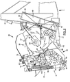
- said feeder means comprise lower feeder means 17, constituted by a front lower feedroll 26, and a smooth, rear lower feedroll 27, and upper feeder means 19, constituted by a front upper feedroll 20 and a rear upper feedroll 21.
- the lower feedrolls 26, 27 are rotatably mounted in a lower feeder frame 24 welded to a transverse beam 32 of a cutterhead frame 34, and the upper feedrolls 20, 21 are mounted in an upper feeder frame 18, to which the row crop attachment 10 is attached.
- the feedrolls 20, 21, 26, 27 rotate to convey the crop material along a crop feeding path inbetween the lower and upper feeder means 17, 19 to a cutterhead 36 which comprises a plurality of knives 37, generating a cylindrical peripheral shape or profile when the cutterhead 36 is rotated about its axle 39.
- the knives 37 cooperate with a fixed shearbar 38 to cut the crop material to length and project it into the bite of a set of counter-rotating crop processor rolls 44, which crack any kernels which may be left in the chopped material and deliver the whole to a blower rotor 49 which is installed within a blower housing 48, attached to vertical beams 51 of the main frame 1.
- the blower rotor 49 comprises a plurality of paddles 50, which throw the material upwardly through the blower outlet into a discharge spout 52 ( Figure 1), which can be positioned by an operator to direct the cut crop material as required, normally into a wagon which is moving alongside or behind the forage harvester.
- the cutterhead axle 39 is journalled on a pair of cutterhead supports 40 of a generally triangular shape, attached to the vertical frame beams 51.
- the cutterhead frame means comprising the cutterhead frame 34, the lower feeder frame 24 and the upper feeder frame 18, are mounted for pivotal movement about the same axle 39.
- the position of this assembly relative to the main frame 1 is controlled by a pair of hydraulic cylinders 41, which are mounted by means of pins 42 between the transverse beam 32 of the cutterhead frame 34 and the main frame 1.
- the upper feeder frame 18 comprises left and right hand side plates 53, each having two substantially vertical apertures 54 through which extend the shafts of the upper feedrolls 20, 21.
- the outer ends of said shafts are received in bearing housings 58, which are movably linked to the upper feeder frame 18 by left and right hand sets of crank arms 56 and load arms 57.
- the crank arms 56 are mounted for pivotal movement to a front portion 60 of the upper feeder frame 18, which registers with the outlet of the row crop attachment 10.
- the rear end of each arm 56 is hingeably linked to the load arm 57, whereof the lower end is pivotally mounted to the bearing housing 58.
- Each load arm 57 comprises a forwardly extending member 62 to which is mounted the upper end of a helical spring 55, whereof the lower end is pivotally mounted to the sides of the front portion 60 of the upper feedroll frame 18.
- the springs 55 force the load arms 57, the bearing housings 58 and the upper feedrolls 20, 21 downwardly to the crop feeding path and rearwardly to the cutterhead 36.
- a first motion damper 64 is installed between the front portion of the bearing housing 58, in the vicinity of the front upper feedroll 20, and the forwardly extending member 62 of the load arm 57.
- a further damper 65 is mounted between the rear portion of the bearing housing 58, in the vicinity of the rear upper feedroll 21, and a stud welded to the top of the upper feeder frame 18. Both dampers 64, 65 may be hydraulic shock absorbers having distinct damping characteristics when elongated or when shortened.
- the lower end of the front portion 60 comprises a pair of bifurcated extensions 66, fitting over a transverse cylindric beam 67 of the lower feeder frame 24.
- the bifurcated extensions 66 are pivotally secured to the beam 67 by means of pins 69.
- the top of the upper feeder frame 18 is held against the cutterhead frame 34 by a pair of eyebolts 70, attached to the sides of the latter frame 34.
- the upper feeder means 19 also comprise a pair of side plates 72 which are affixed by bolts 73 to the bearing housings 58 and extend adjacent the inner sides of the upper feeder frame 18. These plates 72 are moved in unison with the housings 58 and the feedrolls 20, 21 and close off at least partially the apertures 54 in the side plates 53 of the upper feeder frame 18.
- the side plates 72 of the feeder means 19 are interconnected by a transverse tube 74 positioned above the feedrolls 20, 21.
- the tube 74 is removably affixed to the upper feeder means 19 via a pair of flanges 75 welded onto the tube ends.
- a generally cradle-shaped spreader 76 is welded onto the tube 74 beside each flange 75, the longest part of the spreader 76 extending in the for-and-aft direction.
- Continuous, endless belts 77 next to each side plate 53 encircle the spreaders 76 and are clamped thereto by braces 78.
- the belts 77 preferably are rectangular in cross-section and may be reinforced by a high-resistance material such as aramid webbing.
- the top portion of the belts 77 is swung around a profile 79 which is adjustably attached to the top of the upper feeder frame 18 by means of adjustment screws 80.
- the belts 77 are kept in place by a second set of braces 81 which clamp the belts 77 onto the profile 79.
- the long ears of the braces 81 prevent damage to the belts 77 when the feeder means 19 are lifted up and the belts 77 curve upwardly and outwardly.
- the belt suspension is used to define the lowermost position of the movable feeder means 19.
- the front and rear portions of the belts 77 are stretched.
- the front and rear parts of the cradle spreaders 76 are dimensioned as to make the front and rear belt portions, when stretched, extend from the profile 79 in the direction of the axis of the front and rear feedroll 20, 21 respectively.
- the general inclination of the upper feeder means 19 may be varied by sliding the upper portion of the belt 77 slightly forwardly or rearwardly over the supporting profile 79.
- the feedrolls 20, 21 are oriented such that the gap between the rear feedrolls 21, 27 is substantially smaller than the gap between the front feedrolls 20, 26, thereby progressively compressing the crop material which is fed to the cutterhead 36. Swinging movement of the upper feeder means 19 about the profile 79 is precluded by the narrow fit of the rear portion of the bearing housings 58 in the rear apertures 54.
- the minimum distance between the rear feedroll 21 and the smooth feedroll 27 is adjusted by lowering or raising the profile 79 by means of the screws 80. For most crops a minimum distance of about 7 mm has proven to be most satisfactory.
- the position of the movable feedrolls 20, 21 is defined by the lengths of the front and rear belt stretches.
- crop material When crop material is delivered thereto by the attachment 10, it will be compressed into an even mat under action of the springs 55 and the feedrolls 20, 21. The latter are permitted to raise when the height of crop mat increases while the belt 77 is slackened. Irregular feeding may cause the rear or front belt stretch to tension while the other remains slackened. It is no longer required to provide abutments for limiting the downward travel of the movable feedrolls 20, 21.
- the movement of the feedrolls 20, 21 is not hindered in any manner by the pollution of the suspension structure caused by crop material sticking to the belts 77 or the cradle 76. Accumulation of dirt thereon does not influence the stretching or slackening of the belts 77.
- the front and rear belt portions are always stretched to their full lengths when the forage harvester is running empty.
- the front portion 60 When no crop collecting apparatus is attached to the front portion 60, access can be gained to the upper feeder frame 18 for installation, inspection or replacement of the belts 77 by loosening the eyebolts 70 at the top of the feeder frame 18 and tilting the latter forwardly about the cylindric beam 67.
- the top of the front portion 60 may rest on the ground or on any kind of support placed in front of the front unit.
- endless belt 77 may also be replaced with two distinct portions of belt material, or with other flexible suspension means which slacken when the feedrolls are lifted up, such as chains or sets of hinged rods.
- the invention may also be used in feeder arrangements wherein the lower feedrolls 26, 27 are movable and thrust toward the crop path for compressing the incoming crop material. In this case the upward movement of the rolls may be limited by belts installed below the feedrolls 26, 27.
- the suspension according to the invention may also be used in feeder units equipped with other types of conveyor means in replacement of the feedrolls.
Landscapes
- Life Sciences & Earth Sciences (AREA)
- Environmental Sciences (AREA)
- Threshing Machine Elements (AREA)
Abstract
Description
- a main frame;
- cutterhead frame means mounted thereto and enclosing a rotatable cutterhead, operable to comminute crop material conveyed thereto; and
- feeder means, mounted within said cutterhead frame means and operable to convey crop material rearwardly along a crop feeding path towards said cutterhead, said feeder means comprising a portion which is movable between a position adjacent said crop feeding path and a position remote therefrom;
- load means for thrusting said movable portion in the direction of said crop feeding path; and
- retainer means determining the outer position to which said movable portion can be thrust by said load means.
Claims (13)
- A forage harvester, comprisingcharacterized in that said retainer means (74-81) comprise linkage means (77) which are stretched when said movable portion (19) is in said outer position and are slackened when said movable portion is moved to a position remote therefrom.a main frame (1);cutterhead frame means (34, 24, 18) mounted thereto and enclosing a rotatable cutterhead (36), operable to comminute crop material conveyed thereto; andfeeder means (17, 19), mounted within said cutterhead frame means (34, 24, 18) and operable to convey crop material rearwardly along a crop feeding path towards said cutterhead (36), said feeder means (17, 19) comprising a portion (19) which is movable between a position adjacent said crop feeding path and a position remote therefrom;load means (55, 57) for thrusting said movable portion (19) in the direction of said crop feeding path; andretainer means (74-81) determining the outer position to which said movable portion (19) can be thrust by said load means;
- A forage harvester according to claim 1, characterized in that said linkage means (77) have one part affixed to said cutterhead frame means (34, 24, 18) and another part affixed to said movable feeder portion (19).
- A forage harvester according to claim 1 or 2, characterized in that said linkage means comprise at least one belt (77).
- A forage harvester according to claim 3, characterized in that said at least one belt (77) comprises aramid webbing.
- A forage harvester according to claim 3 or 4, characterized in that said linkage means comprise at least one endless, continuous belt (77), encompassing a support means (79) affixed to said frame means (34, 24, 18) and a transverse member (74) of said retainer means (74-81).
- A forage harvester according to claim 5, characterized in that said transverse member (74) is removably attached to said movable feeder portion (19).
- A forage harvester according to any of the preceding claims, characterized in that one part of said linkage means (77) is affixed to a support means (79) which can be moved relative to said frame means (34, 24, 18) for adjusting the outer position of said movable feeder portion (19).
- A forage harvester according to claim 7, characterized in that:said frame means (34, 24, 18) comprise a frame portion (18) into which said movable feeder portion (19) is mounted and which can moved to a position remote from said crop feeding path; andsaid support means (79) is adjustably affixed to said frame portion (18).
- A forage harvester according to any of the preceding claims, characterized in that said linkage means (77) are installed within said cutterhead frame means (34, 24, 18).
- A forage harvester according to claim 8, characterized in that:said movable feeder portion (19) comprises shafts extending through apertures (54) in said frame means (34, 24, 18) and side plates (72) at least partially closing off said apertures (54); andsaid retainer means (74-81) are affixed to said side plates.
- A forage harvester according to any of the preceding claims, characterized in that:said movable feeder portion (19) comprises a front feeder means (20) and a rear feeder means (21); andsaid linkage means (77) comprise front retaining means and rear retaining means determining the outer position of said front feeder means (20) and of said rear feeder means (21) respectively.
- A forage harvester according to claim 11, when appended to claim 5, characterized in that said front and rear retaining means are constituted by front and rear stretches of said endless belt (77).
- A forage harvester according to claim 11 or 12, characterized in that said front and rear feeder means are constituted by front and rear feedrolls (20, 21) and said front and rear retaining means, when stretched, extend from a fixation point (79) stationary to said frame means (34, 24, 18) in the direction of the axes of said front and rear feedrolls (20, 21).
Applications Claiming Priority (2)
| Application Number | Priority Date | Filing Date | Title |
|---|---|---|---|
| GB9706454 | 1997-03-27 | ||
| GB9706454A GB2323512A (en) | 1997-03-27 | 1997-03-27 | Forage harvester |
Publications (2)
| Publication Number | Publication Date |
|---|---|
| EP0872171A1 true EP0872171A1 (en) | 1998-10-21 |
| EP0872171B1 EP0872171B1 (en) | 2002-08-28 |
Family
ID=10810017
Family Applications (1)
| Application Number | Title | Priority Date | Filing Date |
|---|---|---|---|
| EP98200825A Expired - Lifetime EP0872171B1 (en) | 1997-03-27 | 1998-03-16 | Feeder means for a forage harvester |
Country Status (4)
| Country | Link |
|---|---|
| US (1) | US5976012A (en) |
| EP (1) | EP0872171B1 (en) |
| DE (1) | DE69807384T2 (en) |
| GB (1) | GB2323512A (en) |
Cited By (3)
| Publication number | Priority date | Publication date | Assignee | Title |
|---|---|---|---|---|
| EP1277395A1 (en) * | 2001-07-19 | 2003-01-22 | CLAAS Selbstfahrende Erntemaschinen GmbH | Method for chopping a strand of crop material and device for performing the method |
| EP1342403A1 (en) * | 2002-03-09 | 2003-09-10 | CNH Belgium N.V. | Springsystem for upper feed rolls of a forage harvester |
| EP2409563A1 (en) | 2010-07-22 | 2012-01-25 | CNH Belgium N.V. | In-feed apparatus for a forage harvester |
Families Citing this family (8)
| Publication number | Priority date | Publication date | Assignee | Title |
|---|---|---|---|---|
| US6073431A (en) * | 1997-12-29 | 2000-06-13 | New Holland North America, Inc. | Self-propelled windrower |
| GB2474290A (en) * | 2009-10-09 | 2011-04-13 | Agco Gmbh | A compression roll housing having slots provided with bristles |
| DE102010002343A1 (en) * | 2010-02-25 | 2011-08-25 | Deere & Company, Ill. | Forage harvester with a chopper and a post-processing device arranged downstream of the chopper |
| US9486806B1 (en) | 2011-04-01 | 2016-11-08 | Claas Saulgau Gmbh | System and method for processing crop materials into livestock feed and the product thereof |
| DE102013112326A1 (en) * | 2013-11-08 | 2015-05-13 | Claas Saulgau Gmbh | Feeder housing and harvester equipped therewith |
| GB201603728D0 (en) | 2016-03-03 | 2016-04-20 | Agco Int Gmbh | Compression roll housing |
| DE102016118561B4 (en) | 2016-09-29 | 2024-01-18 | Claas Saulgau Gmbh | collection plant |
| DE102017111172A1 (en) | 2017-05-22 | 2018-11-22 | Claas Saulgau Gmbh | infeed |
Citations (6)
| Publication number | Priority date | Publication date | Assignee | Title |
|---|---|---|---|---|
| DE539522C (en) * | 1931-11-30 | Karl Trautz Fa | Device for lifting the top roller and the press cover on Haecksel machines | |
| GB2024590A (en) * | 1978-07-05 | 1980-01-16 | Deere & Co | Forage harvester |
| GB2037556A (en) * | 1978-11-21 | 1980-07-16 | Poettinger Ohg Alois | Chaff cutter and feeding mechanism thereof |
| NL9101234A (en) * | 1991-07-12 | 1993-01-04 | Wilhelmus Hendricus Knuiman En | Chopping device |
| EP0541975A1 (en) * | 1991-11-11 | 1993-05-19 | Claas Saulgau Gmbh | Loading house for a forage harvester |
| EP0656172A1 (en) * | 1993-12-04 | 1995-06-07 | New Holland Belgium N.V. | Front unit for a forage harvester |
Family Cites Families (4)
| Publication number | Priority date | Publication date | Assignee | Title |
|---|---|---|---|---|
| US3127723A (en) * | 1961-03-24 | 1964-04-07 | Sperry Rand Corp | Row crop forage harvester and crop feed means |
| US4821494A (en) * | 1985-12-05 | 1989-04-18 | Hay & Forage Industries | Crop harvester having conditioning zone provided with enlarged end regions |
| US5152127A (en) * | 1991-06-21 | 1992-10-06 | The United States Of America, As Represented By The Secretary Of Agriculture | Process and apparatus to improve the properties and value of forage crops |
| DE4228857A1 (en) * | 1992-08-29 | 1994-03-03 | Kloeckner Humboldt Deutz Ag | Device for processing straw |
-
1997
- 1997-03-27 GB GB9706454A patent/GB2323512A/en not_active Withdrawn
-
1998
- 1998-03-16 DE DE69807384T patent/DE69807384T2/en not_active Expired - Lifetime
- 1998-03-16 EP EP98200825A patent/EP0872171B1/en not_active Expired - Lifetime
- 1998-03-23 US US09/046,339 patent/US5976012A/en not_active Expired - Fee Related
Patent Citations (6)
| Publication number | Priority date | Publication date | Assignee | Title |
|---|---|---|---|---|
| DE539522C (en) * | 1931-11-30 | Karl Trautz Fa | Device for lifting the top roller and the press cover on Haecksel machines | |
| GB2024590A (en) * | 1978-07-05 | 1980-01-16 | Deere & Co | Forage harvester |
| GB2037556A (en) * | 1978-11-21 | 1980-07-16 | Poettinger Ohg Alois | Chaff cutter and feeding mechanism thereof |
| NL9101234A (en) * | 1991-07-12 | 1993-01-04 | Wilhelmus Hendricus Knuiman En | Chopping device |
| EP0541975A1 (en) * | 1991-11-11 | 1993-05-19 | Claas Saulgau Gmbh | Loading house for a forage harvester |
| EP0656172A1 (en) * | 1993-12-04 | 1995-06-07 | New Holland Belgium N.V. | Front unit for a forage harvester |
Cited By (4)
| Publication number | Priority date | Publication date | Assignee | Title |
|---|---|---|---|---|
| EP1277395A1 (en) * | 2001-07-19 | 2003-01-22 | CLAAS Selbstfahrende Erntemaschinen GmbH | Method for chopping a strand of crop material and device for performing the method |
| EP1342403A1 (en) * | 2002-03-09 | 2003-09-10 | CNH Belgium N.V. | Springsystem for upper feed rolls of a forage harvester |
| EP2409563A1 (en) | 2010-07-22 | 2012-01-25 | CNH Belgium N.V. | In-feed apparatus for a forage harvester |
| BE1019429A3 (en) * | 2010-07-22 | 2012-07-03 | Cnh Belgium Nv | FOOD DEVICE FOR A FIELD FORMER. |
Also Published As
| Publication number | Publication date |
|---|---|
| EP0872171B1 (en) | 2002-08-28 |
| DE69807384D1 (en) | 2002-10-02 |
| GB2323512A (en) | 1998-09-30 |
| GB9706454D0 (en) | 1997-05-14 |
| US5976012A (en) | 1999-11-02 |
| DE69807384T2 (en) | 2003-10-23 |
Similar Documents
| Publication | Publication Date | Title |
|---|---|---|
| US5005343A (en) | Header for a combine harvesting machine | |
| US3940913A (en) | Row crop harvesting apparatus | |
| US4956966A (en) | Header for a combine harvesting machine | |
| US4177625A (en) | Pull-type agricultural machine | |
| US4187664A (en) | Agricultural machine structure | |
| EP1733609B1 (en) | Pick-up and large round baler | |
| EP0872171B1 (en) | Feeder means for a forage harvester | |
| US4463546A (en) | Windrow pickup mechanism | |
| US5052170A (en) | Shredder attachment for round hay baler | |
| EP3308624A1 (en) | Combine feeder house gauge wheels | |
| CA1166921A (en) | Tensioning mechanism for feeder conveyor positioned within feeder housing | |
| US3517491A (en) | Header suspension mounting for pull-type harvesters | |
| US3397520A (en) | Hay harvesting and conditioning device | |
| US5498207A (en) | Front unit for a forage harvester | |
| HU192308B (en) | Silo combine | |
| CA3158538A1 (en) | Agricultural header with inter-belt crop divider | |
| EP0100628B2 (en) | Apparatus and method for picking up and conveying crop | |
| EP0664077A1 (en) | Compressor rolls for a forage harvester | |
| US3483688A (en) | Chopper and baler assembly | |
| EP2409563B1 (en) | In-feed apparatus for a forage harvester | |
| US5443421A (en) | Rock discharge assembly for hay crusher | |
| US10375889B2 (en) | Dual belt conveyor for agricultural machine | |
| EP0797914B1 (en) | Feeder means for a forage harvester | |
| RU2267903C2 (en) | Apparatus for grinding of plant undergrowth and mechanism for joining to adapters | |
| US3402533A (en) | Hay harvesting and conditioning device |
Legal Events
| Date | Code | Title | Description |
|---|---|---|---|
| PUAI | Public reference made under article 153(3) epc to a published international application that has entered the european phase |
Free format text: ORIGINAL CODE: 0009012 |
|
| AK | Designated contracting states |
Kind code of ref document: A1 Designated state(s): DE FR GB |
|
| AX | Request for extension of the european patent |
Free format text: AL;LT;LV;MK;RO;SI |
|
| 17P | Request for examination filed |
Effective date: 19990402 |
|
| AKX | Designation fees paid |
Free format text: DE FR GB |
|
| GRAG | Despatch of communication of intention to grant |
Free format text: ORIGINAL CODE: EPIDOS AGRA |
|
| 17Q | First examination report despatched |
Effective date: 20010827 |
|
| GRAG | Despatch of communication of intention to grant |
Free format text: ORIGINAL CODE: EPIDOS AGRA |
|
| GRAH | Despatch of communication of intention to grant a patent |
Free format text: ORIGINAL CODE: EPIDOS IGRA |
|
| GRAH | Despatch of communication of intention to grant a patent |
Free format text: ORIGINAL CODE: EPIDOS IGRA |
|
| GRAA | (expected) grant |
Free format text: ORIGINAL CODE: 0009210 |
|
| AK | Designated contracting states |
Kind code of ref document: B1 Designated state(s): DE FR GB |
|
| REG | Reference to a national code |
Ref country code: GB Ref legal event code: FG4D |
|
| REF | Corresponds to: |
Ref document number: 69807384 Country of ref document: DE Date of ref document: 20021002 |
|
| ET | Fr: translation filed | ||
| PLBE | No opposition filed within time limit |
Free format text: ORIGINAL CODE: 0009261 |
|
| STAA | Information on the status of an ep patent application or granted ep patent |
Free format text: STATUS: NO OPPOSITION FILED WITHIN TIME LIMIT |
|
| 26N | No opposition filed |
Effective date: 20030530 |
|
| REG | Reference to a national code |
Ref country code: FR Ref legal event code: CD |
|
| REG | Reference to a national code |
Ref country code: GB Ref legal event code: 746 Effective date: 20090114 |
|
| REG | Reference to a national code |
Ref country code: DE Ref legal event code: R082 Ref document number: 69807384 Country of ref document: DE Representative=s name: PATENTANWAELTE WALLACH, KOCH & PARTNER, DE |
|
| PGFP | Annual fee paid to national office [announced via postgrant information from national office to epo] |
Ref country code: DE Payment date: 20140118 Year of fee payment: 17 |
|
| PGFP | Annual fee paid to national office [announced via postgrant information from national office to epo] |
Ref country code: FR Payment date: 20140115 Year of fee payment: 17 |
|
| REG | Reference to a national code |
Ref country code: DE Ref legal event code: R082 Ref document number: 69807384 Country of ref document: DE Representative=s name: PATENTANWAELTE WALLACH, KOCH, DR. HAIBACH, FEL, DE Effective date: 20140428 Ref country code: DE Ref legal event code: R082 Ref document number: 69807384 Country of ref document: DE Representative=s name: PATENTANWAELTE WALLACH, KOCH & PARTNER, DE Effective date: 20140428 Ref country code: DE Ref legal event code: R081 Ref document number: 69807384 Country of ref document: DE Owner name: CNH INDUSTRIAL BELGIUM NV, BE Free format text: FORMER OWNER: CNH BELGIUM NV, ZEDELGEM, BE Effective date: 20140428 |
|
| PGFP | Annual fee paid to national office [announced via postgrant information from national office to epo] |
Ref country code: GB Payment date: 20140120 Year of fee payment: 17 |
|
| REG | Reference to a national code |
Ref country code: FR Ref legal event code: CD Owner name: CNH INDUSTRIAL BELGIUM NV Effective date: 20140725 |
|
| REG | Reference to a national code |
Ref country code: DE Ref legal event code: R119 Ref document number: 69807384 Country of ref document: DE |
|
| GBPC | Gb: european patent ceased through non-payment of renewal fee |
Effective date: 20150316 |
|
| REG | Reference to a national code |
Ref country code: FR Ref legal event code: ST Effective date: 20151130 |
|
| PG25 | Lapsed in a contracting state [announced via postgrant information from national office to epo] |
Ref country code: GB Free format text: LAPSE BECAUSE OF NON-PAYMENT OF DUE FEES Effective date: 20150316 Ref country code: DE Free format text: LAPSE BECAUSE OF NON-PAYMENT OF DUE FEES Effective date: 20151001 |
|
| PG25 | Lapsed in a contracting state [announced via postgrant information from national office to epo] |
Ref country code: FR Free format text: LAPSE BECAUSE OF NON-PAYMENT OF DUE FEES Effective date: 20150331 |