EP0100628B2 - Apparatus and method for picking up and conveying crop - Google Patents
Apparatus and method for picking up and conveying crop Download PDFInfo
- Publication number
- EP0100628B2 EP0100628B2 EP19830304221 EP83304221A EP0100628B2 EP 0100628 B2 EP0100628 B2 EP 0100628B2 EP 19830304221 EP19830304221 EP 19830304221 EP 83304221 A EP83304221 A EP 83304221A EP 0100628 B2 EP0100628 B2 EP 0100628B2
- Authority
- EP
- European Patent Office
- Prior art keywords
- crop
- hood
- rotor
- movement
- along
- Prior art date
- Legal status (The legal status is an assumption and is not a legal conclusion. Google has not performed a legal analysis and makes no representation as to the accuracy of the status listed.)
- Expired
Links
Images

Classifications
-
- A—HUMAN NECESSITIES
- A01—AGRICULTURE; FORESTRY; ANIMAL HUSBANDRY; HUNTING; TRAPPING; FISHING
- A01D—HARVESTING; MOWING
- A01D89/00—Pick-ups for loaders, chaff-cutters, balers, field-threshers, or the like, i.e. attachments for picking-up hay or the like field crops
- A01D89/006—Accessories
- A01D89/008—Devices cooperating with the pick-up
-
- A—HUMAN NECESSITIES
- A01—AGRICULTURE; FORESTRY; ANIMAL HUSBANDRY; HUNTING; TRAPPING; FISHING
- A01D—HARVESTING; MOWING
- A01D43/00—Mowers combined with apparatus performing additional operations while mowing
- A01D43/10—Mowers combined with apparatus performing additional operations while mowing with means for crushing or bruising the mown crop
- A01D43/102—Bruising control devices
-
- A—HUMAN NECESSITIES
- A01—AGRICULTURE; FORESTRY; ANIMAL HUSBANDRY; HUNTING; TRAPPING; FISHING
- A01D—HARVESTING; MOWING
- A01D57/00—Delivering mechanisms for harvesters or mowers
-
- A—HUMAN NECESSITIES
- A01—AGRICULTURE; FORESTRY; ANIMAL HUSBANDRY; HUNTING; TRAPPING; FISHING
- A01D—HARVESTING; MOWING
- A01D82/00—Crop conditioners, i.e. machines for crushing or bruising stalks
Definitions
- the present invention relates to apparatus and method for picking up and conveying crop, and relates in particular but not exclusively to apparatus including a rotor for picking up previously cut forage crops such as grass from the ground and for conveying such crops into chopping, baling or other harvesting apparatus, whether or not such action includes conditioning of the crop.
- a housing comprising for example a hood, also known as a shroud or cowling, over at least the front part of the rotor.
- a hood also known as a shroud or cowling
- the exit clearance needs to be greater than the intake clearance, so that crop can start to disengage itself from the rotor elements early, and a compact stream is formed on completion of the process.
- the shape of the hood in the exit region determines the trajectory of the resultant crop stream.
- an apparatus for cutting and conveying crop comprising a rotor mounted for rotation about an axis parallel to the ground for picking up and conveying crop, a hood extending over the front of the rotor and defining with the rotor a crop flow passage along which crop is conveyed by the rotor, and drive means rotating the rotor in a sense such that the rotor picks up the crop and carries it upwardly and rearwardly over the rotor.
- a forward part of the hood is hinged to the rear part of the same hood, so as to be movable during operation, but the movement is simple hinged movement giving merely the effect of a flap lifting at the front of the hood.
- apparatus for picking up and conveying crop comprising a mobile frame for movement across the ground, a conveying rotor mounted for rotation about an axis transverse to the direction of forward movement of the apparatus and substantially parallel to the ground for picking up and conveying crop, a hood extending at least around part of the front half of the rotor and defining between the hood and part of the outer periphery of the rotor a crop flow passage along which crop is conveyed by the rotor, drive means for driving the conveying rotor in rotation in a sense such that the rotor picks up crop and carries the crop upwardly and rearwardly over the rotor, and mounting means for mounting the hood so as to be moveable relative to the frame during operation, the hood being moveable in response to, and by the effect of, the crop to effect automatic adjustment of the hood position by the direct effect of the crop on the hood, the hood being mounted in such a manner that an increase in crop load increases both the vertical clearance between the front of the
- the movement of the hood by which the automatic adjustment of clearance is made includes a component which is a readily outward movement relative to the rotor, and it may differ in magnitude from one side and one end of the rotor housing to the other.
- the mounting means constrains the said hood to move along a substantially predetermined path in response to, and by the effect of, changes in crop load.
- Adjustment means may be provided for selectively varying the predetermined path of movement of the hood. It may be arranged that the said predetermined path produces different variations of clearances at the entrance and exit of the crop flow passage during movement of the hood. In such a case there may be provide means for adjusting the relationship between the different variations in clearances at the entrance and exit of the crop flow passage.
- the relationship between the different variations in clearances at the inlet and outlet of the crop passage can be adjusted by varying the mounting of the hood.
- the hood is movable in response to, and by the effect of, an increase in crop load to effect an overall increase in the clearance presented to the crop along the crop flow passage.
- the clearance presented to the crop along the crop passage is not normally at any point reduced in response to an increase in crop load, although it may be that the clearance is at some points unaltered.
- the present invention permits this to be achieved.
- the hood may be biassed towards a position of greater restriction to crop (that is to say giving a smaller clearance for crop flow) by gravity, either alone or in combination with biassing means coupled between the frame and the hood.
- the additional biassing means may act to increase or decrease the biassing effect due to gravity.
- the actual mounting means for the hood may take a wide variety of forms, yet still fulfil the requirements of the inveniton as set out above.
- the mounting means may comprise at least two mounting linkages spaced apart along the direction of crop flow through the crop flow passage.
- Each mounting linkage may comprise a pivotal mounting linkage which is pivoted to the hood and to the frame, the spacing between the pivots on the linkages being different for different linkages along the crop passage, so that a different variation of clearance occurs at diffeent positions along the crop passage.
- Each said mounting linkage may comprise an arm pivoted at one end to the hood and pivoted at the other end to the frame.
- the said mounting means may comprise spigots movably mounted in slots in substantially vertical side walls of the apparatus.
- the mounting means may be formed partly or entirely by elastic links, to allow lateral differentiation in the response to different crop loads.
- the said frame includes a pair of laterally spaced side walls, the said hood being wider than the lateral spacing of the side walls and on the upper edges of the side walls being arranged to form lower limit stops for the hood, movement of the hood above the side walls being produced by extension of independent elastic links in a non-predetermined path. It may be arranged that rollers or wheels are attached near the upper ends of the side walls to support and guide the overhanging hood and to minimise sliding friction, and that the rollers or wheels are made from resilient material to cushion the return movement of the hood.
- the said frame of the apparatus may include side plates of the general rotor housing.
- the hood may be biassed towards a position of greater restriction of crop by gravity, either alone or in combination with biassing means coupled between the frame and the hood or hood portion.
- the said hood may be formed by two or more hood sections positioned transversely adjacent across the width of the apparatus relative to the intended direction of forward movement, such that the restriction on crop movement between the hood and the rotor may be varied to different extents at different positions across the width of the apparatus in dependence upon different amounts of crop presented at different positions across the width of the apparatus.
- a curtain member suspended at the front of the apparatus a head of the inlet to the crop passage between the hood and the rotor, the curtain member being movable in response to and by the effect of crop between a first position in which the curtain member hangs freely and substantially vertically and a second position in which the curtain member trails non-vertically from its suspension region and provides a guide surface above the crop leading into the crop passage between the rotor and the hood.
- a method of picking up and conveying crop comprising the steps of moving a mobile frame across the ground, rotating a conveying rotor about an axis transverse to the direction of forward movement of the apparatus and substantially parallel to the ground for picking up and conveying crop, picking up crop by the rotor and carrying the crop upwardly and rearwardly over the rotor along a crop flow passage defined between a hood extending at least around part of the front half of the rotor, and part of the outer periphery of the rotor, and automatically adjusting the entrance to the crop flow passage by moving the hood relative to the frame during operation, in response to changes in crop load and by the direct effect of the crop of the hood, the movement of the hood being such that an increase in crop load increases both the vertical clearance between the front of the hood and the ground and the horizontal clearance between the front of the hood and the rotor at the entrance to the crop flow passage characterised by effecting movement of the hood such that the said increase in crop load produces movement
- the rotor referred to above may comprise for example a rotor having a plurality of outwardly directed spring steel tines for picking up cut fodder crop such as grass.
- the invention is particularly applicable when used with a rotor as set out in our published UK Patent 1322165, comprising a plurality of outwardly directed metal spokes in the form of V-shaped crop engaging elements, or a rotor as set out in our published pending UK Patent Application No. 2075816A, which comprises a brush-like structure having a multiplicity of stiff resilient elongate elements which are arranged in tufts of brush elements spaced apart along the axis of the rotor; or a rotor as set out in our published pending UK Patent Application Nos. 2099272A and 2107963A, both of which disclose pick-up and conditioning rotors in which the crop engaging elements are formed of thick, stiff, plastics sheeting.
- a crop pick-up apparatus comprising a rotor 11 mounted on a mobile main frame (not shown) for movement over the ground 13 to pick-up previously cut crop.
- a hood assembly or rotor housing is indicated generally at 15, and includes an overhead baffle or deflector 17.
- the rotor 11 preferably consists of a plurality of stiff resilient outwardly directed crop engaging elements, the outer periphery of which is indicated by a broken line 21.
- the rotor 11 comprises a pick-up rotor as disclosed in one of our published UK Patent Application No. 2075816A, 2099272A and 2107963A.
- the rotor 11 is rotated in a clockwise direction so as to pick-up cut crop from the ground and to convey the crop upwardly and rearwardly over the rotor 11.
- the crop material is conveyed upwardly and to the rear of the apparatus beneath the baffle or deflector 17 above the rotor.
- the deflector 17 may be a flat or curved plate.
- the gap shown and indicated at 24 allows the operator to see the crop stream to check operation, and also facilitates, if desirable, the introduction and even distribution of additives in liquid or solid form.
- the protective curtain 19 is suspended from the rigid bar 20 preceding the rotor 11.
- the curtain 19 serves the additional purpose of guiding the crop.
- the curtain 19 is shown in its rest position in full lines, and in broken lines there is shown the normal deflected position of the curtain 19 during forward movement of the apparatus over crop.
- a hood 18 with side flanges 29 is shown to be located by spigots 22 in lower arcuate slots 23, and by spigots 30 in upper linear slots 31.
- the extreme position to which the hood member 18 can be moved in response to increased crop pressure is shown in broken lines. It will be seen that the upper clearance of the hood 18 from the rotor 11, and also the angle of the hood 18, have changed with movement of the hood 18 from the full line to the broken line positions, in addition to the change brought about at the lower end of the hood 18.
- spring loading of the hood 18 to increase or decrease its resistance to deflection may be provided.
- a transverse cracking bar may be provided at the lower portion of the hood 18; the bar may be continuous or may provide an intermittent edge.
- Figure 2 shows a further modification of the apparatus described thus far, and discloses firstly a modification of the mounting for the hood 18 of Figure 1.
- the hood 18 is shown to be suspended and pivoted on upper and lower link arms 32 and 33 which are pivoted respectively at fixed pivot points 34 and 35 which are fixed relative to the main frame (not shown).
- the upper and lower link arms 32 and 33 are so dimensioned and angled that, by way of example, the upper end of the hood 18 moves slightly further away from the periphery 21 of the rotor 11 than does the lower end of the hood 18, during movement of the hood 18 from the full line position to the broken line position shown.
- the hood 18 is shown to be spring loaded to increase its resistance to deflection, the spring loading being shown diagrammatically at 36.
- hood suspension may be used, including suspensions consisting mainly or entirely of springs or elastomeric elements, to make the hood responsive to changes of load.
- Elastic links allow additional lateral differentiation in the response to different crop loads.
- Figure 2 also illustrates a feature concerned with the collection of stray pieces of crop which may escape from the main stream of crop leaving the pick-up rotor.
- a transverse auger 37 which has beneath it a conventional concave trough 38.
- the main crop stream may will leave the rotor 11 generally along the direction indicated diagrammatically by the arrow 39, but some stray pieces of crop will fall downwardly with the rotating rotor 11 and would normally fall to the ground in a region indicated diagrammatically at 40.
- a further concave guide member 41 which leads around, and is spaced from the underside of the rotor 11.
- the guide member 41 leads from the forward edge of the trough 38 and terminates just rearwardly of the bottom dead centre position of the rotor 11.
- a supporting member 42 is positioned to the rear of the guide member 41.
- the guide member 41 collects stray pieces of crop material and forces them to be guided downwardly and forwardly by the rotor 11 to be re-introduced into the crop layer in front of the rotor 11.
- the guide member 41 may be sharpened at its lower leading edge 43.
- the support member 42 behind the guide member 41 maintains the guide member 41 in fixed relationship with the rotor 11.
- the general main frame of the apparatus is referred to by the numeral 50, and a pick-up rotor 11 is mounted between substantial side plates 51 of the frame 50 and is driven from the pto 52 of a tractor through a conventional drive linkage terminating at 53 ( Figure 3).
- the rotor 11 is formed of a brush-like structure as set out in our previous published UK Patent Application No. 2075816A, although the crop engaging elements need not necessarily be multi-filamented brush tufts but can be of alternative construction (including a one-piece construction) and can be made from flexible material or resiliently mounted rigid material, and in such cases are preferably shaped to be tapering towards their crop engaging tips, to assist crop detachment and transfer into, for example, a forage harvester feed mechanism.
- a curved hood 54 extends over the front of the rotor 11, and in the paticular example shown is formed of transparent synthetic plastics material, which allows an operator of the apparatus to view the operation of the rotor.
- the hood 54 is mounted by two pivoted arms 55 and 56 to the side plate 51 of the main frame 50, and corresponding pivoted arms are provided on the other side of the apparatus.
- the pivot arm 55 is pivoted to the hood 54 at a pivot 57, and to the side plate 51 at a pivot 59, and the arm 56 is correspondingly pivoted at pivots 58 and 60. Provision is made at apertures 60' for the pivot point 60 to be moved relative to the side plate 51.
- the main structure is completed by side panels 61 and side skids 62, repeated on the other side of the apparatus.
- the hood 54 is shown at its lowermost and most forward position, and the hood is shown at this position in Figure 4 in full lines.
- the hood 54 is movable by pivoting on the arms 55 and 56, the pivots 57 and 58 moving in slots 63 and 64 in side panels 61 of the apparatus, of which one is shown in Figure 3(a).
- the side panels 61 are held in frames having horizontal cross members 66 and 67, and movement of the hood 64 is limited by stops 72 and 73 carried on the arm 56, and bearing against the cross member 66 and 67.
- a biasing device 68 is linked by an arm 69 to the side frame 51, and biases the hood into the forward and downward position by the effect of the spring 70 acting between the base of the biasing means 68 and the link 69.
- the apparatus is supported on skids 62 of which one is shown in Figure 3(a) secured to the side plate 51.
- FIG. 5(a) and 5(b) there are shown in diagrammatic side cross section and front view respectively a pick-up rotor for picking up crop on the ground, and embodying the invention.
- Side plates 90 attached to a ground skid 91 on each side of the apparatus are shaped at the top to support a rotor hood 16' which laterally overhangs the side plates 90.
- the hood 16' is secured only by two or more springs 92 and 93 which are shown diagrammatically coupled between the hood 16' and securing portions 94 of the side plates 90.
- the directional pull of the springs 92 and 93 is arranged to be downwardly and forwardly at the front against limit stops (not shown) and towards the rotor centre against resilient buffers (also not shown) which prevent noise arising from metal-to-metal contact.
- Small rubber wheels or rollers 95 and 96 produce the desired damping effect and reduce sliding friction of the hood 16' sliding across the top of the side plates 90.
- the springs and their direction of fitting shown are merely an example, and it should be noted that compression or tension springs can be used, including telescopic spring loaded arms.
- the rotor hood 16' may have one or more transverse hinges (not shown) which, in combination with the springs arranged to act near the hinges axes, to give maximum freedom of response.
- a rotor cover which is wider than the lateral spacing of the rotor housing side plates, so that the upper edges of the side plates form the lower limit stops and movement of the housing above the side plates can correspond to the extension of independent elastic links in a non-predetermined path.
- Advantageously rollers or wheels attached near the upper ends of the side plates support and guide the overhanging rotor cover and minimise sliding friction.
- the rollers or wheels may be made from resilient material to cushion the return movement of the rotor housing.
- crop load is meant the amount and/or the nature of the crop picked up and conveyed by the rotor.
- the crop load may be increased by an increase in the amount of crop conveyed by the rotor, or by an increase in the friction exerted by the crop conveyed by the rotor, or by both factors. Friction may be increased for example by an increase in wetness of the crop.
Description
- The present invention relates to apparatus and method for picking up and conveying crop, and relates in particular but not exclusively to apparatus including a rotor for picking up previously cut forage crops such as grass from the ground and for conveying such crops into chopping, baling or other harvesting apparatus, whether or not such action includes conditioning of the crop.
- In order to make it possible for high-speed crop engaging rotors to lift fibrous crops for purposes of conveying, or treating and conveying, the material, it is necessary to provide a housing, comprising for example a hood, also known as a shroud or cowling, over at least the front part of the rotor. The shape of the hood and its relative position to the rotor, particularly the vertical clearance above the crop layer to be engaged and the radial clearance at the intake and exit regions, vitally affect the performance and power requirement of the unit as a whole. Normally, but not necessarily, the exit clearance needs to be greater than the intake clearance, so that crop can start to disengage itself from the rotor elements early, and a compact stream is formed on completion of the process. The shape of the hood in the exit region determines the trajectory of the resultant crop stream.
- Because crop yields may vary from very light to exceptionally heavy, adjustment is needed in the vertical and radial clearances of the hood at the intake region. In a sparse crop, both clearances need to be small, to avoid crop being thrown forwardly and rejected by the rotor. The converse applies when bulky swaths or windrows are to be collected. In conventional machines a manual adjustment is usually provided which can be set according to estimated crop conditions.
- In Austrian patent No. AT-B-304122 (equivalent to British patent No. GB-A-1214840 (Vis- sers)), an apparatus for cutting and conveying crop is shown, comprising a rotor mounted for rotation about an axis parallel to the ground for picking up and conveying crop, a hood extending over the front of the rotor and defining with the rotor a crop flow passage along which crop is conveyed by the rotor, and drive means rotating the rotor in a sense such that the rotor picks up the crop and carries it upwardly and rearwardly over the rotor. A forward part of the hood is hinged to the rear part of the same hood, so as to be movable during operation, but the movement is simple hinged movement giving merely the effect of a flap lifting at the front of the hood.
- It is an object of the present invention to avoid or reduce the difficulties found in practice of manually adjusting the crop flow passage associated with a crop pick-up rotor.
- According to the present invention there is provided apparatus for picking up and conveying crop comprising a mobile frame for movement across the ground, a conveying rotor mounted for rotation about an axis transverse to the direction of forward movement of the apparatus and substantially parallel to the ground for picking up and conveying crop, a hood extending at least around part of the front half of the rotor and defining between the hood and part of the outer periphery of the rotor a crop flow passage along which crop is conveyed by the rotor, drive means for driving the conveying rotor in rotation in a sense such that the rotor picks up crop and carries the crop upwardly and rearwardly over the rotor, and mounting means for mounting the hood so as to be moveable relative to the frame during operation, the hood being moveable in response to, and by the effect of, the crop to effect automatic adjustment of the hood position by the direct effect of the crop on the hood, the hood being mounted in such a manner that an increase in crop load increases both the vertical clearance between the front of the hood and the ground and the horizontal clearance between the front of the hood and the rotor at the entrance to the crop flow passage, characterised in that the hood is mounted in such a manner that the said increase in crop load produces movement of the hood in the direction of crop flow by movement of the whole moveable hood along a path spaced from and lying around the outer periphery of the rotor.
- The movement of the hood by which the automatic adjustment of clearance is made includes a component which is a readily outward movement relative to the rotor, and it may differ in magnitude from one side and one end of the rotor housing to the other.
- It is preferred that the mounting means constrains the said hood to move along a substantially predetermined path in response to, and by the effect of, changes in crop load. Adjustment means may be provided for selectively varying the predetermined path of movement of the hood. It may be arranged that the said predetermined path produces different variations of clearances at the entrance and exit of the crop flow passage during movement of the hood. In such a case there may be provide means for adjusting the relationship between the different variations in clearances at the entrance and exit of the crop flow passage.
- Conveniently the relationship between the different variations in clearances at the inlet and outlet of the crop passage can be adjusted by varying the mounting of the hood.
- Normally it will be arranged that the hood is movable in response to, and by the effect of, an increase in crop load to effect an overall increase in the clearance presented to the crop along the crop flow passage. By this is meant that the clearance presented to the crop along the crop passage is not normally at any point reduced in response to an increase in crop load, although it may be that the clearance is at some points unaltered. However, were it required, for example, than an increase in clearance at the front is compensated by a decrease in clearance at the rear of the housing, the present invention permits this to be achieved.
- The hood may be biassed towards a position of greater restriction to crop (that is to say giving a smaller clearance for crop flow) by gravity, either alone or in combination with biassing means coupled between the frame and the hood. The additional biassing means may act to increase or decrease the biassing effect due to gravity.
- The actual mounting means for the hood may take a wide variety of forms, yet still fulfil the requirements of the inveniton as set out above.
- In some arrangements the mounting means may comprise at least two mounting linkages spaced apart along the direction of crop flow through the crop flow passage.
- Each mounting linkage may comprise a pivotal mounting linkage which is pivoted to the hood and to the frame, the spacing between the pivots on the linkages being different for different linkages along the crop passage, so that a different variation of clearance occurs at diffeent positions along the crop passage. Each said mounting linkage may comprise an arm pivoted at one end to the hood and pivoted at the other end to the frame.
- In yet another arrangement, the said mounting means may comprise spigots movably mounted in slots in substantially vertical side walls of the apparatus.
- In yet other arrangements the mounting means may be formed partly or entirely by elastic links, to allow lateral differentiation in the response to different crop loads.
- In one form, the said frame includes a pair of laterally spaced side walls, the said hood being wider than the lateral spacing of the side walls and on the upper edges of the side walls being arranged to form lower limit stops for the hood, movement of the hood above the side walls being produced by extension of independent elastic links in a non-predetermined path. It may be arranged that rollers or wheels are attached near the upper ends of the side walls to support and guide the overhanging hood and to minimise sliding friction, and that the rollers or wheels are made from resilient material to cushion the return movement of the hood.
- It is to be appreciated that the said frame of the apparatus may include side plates of the general rotor housing.
- In any of these arrangements, the hood may be biassed towards a position of greater restriction of crop by gravity, either alone or in combination with biassing means coupled between the frame and the hood or hood portion.
- In some preferred arrangements, the said hood may be formed by two or more hood sections positioned transversely adjacent across the width of the apparatus relative to the intended direction of forward movement, such that the restriction on crop movement between the hood and the rotor may be varied to different extents at different positions across the width of the apparatus in dependence upon different amounts of crop presented at different positions across the width of the apparatus.
- In addition to the features set out hereinbefore, it is particularly preferred that there may be provided a curtain member suspended at the front of the apparatus a head of the inlet to the crop passage between the hood and the rotor, the curtain member being movable in response to and by the effect of crop between a first position in which the curtain member hangs freely and substantially vertically and a second position in which the curtain member trails non-vertically from its suspension region and provides a guide surface above the crop leading into the crop passage between the rotor and the hood.
- There is also provided in accordance with the present invention a method of picking up and conveying crop comprising the steps of moving a mobile frame across the ground, rotating a conveying rotor about an axis transverse to the direction of forward movement of the apparatus and substantially parallel to the ground for picking up and conveying crop, picking up crop by the rotor and carrying the crop upwardly and rearwardly over the rotor along a crop flow passage defined between a hood extending at least around part of the front half of the rotor, and part of the outer periphery of the rotor, and automatically adjusting the entrance to the crop flow passage by moving the hood relative to the frame during operation, in response to changes in crop load and by the direct effect of the crop of the hood, the movement of the hood being such that an increase in crop load increases both the vertical clearance between the front of the hood and the ground and the horizontal clearance between the front of the hood and the rotor at the entrance to the crop flow passage characterised by effecting movement of the hood such that the said increase in crop load produces movement of the hood in the direction of crop flow by movement of the whole moveable hood along a path spaced from and lying around the outer periphery of the rotor.
- In general, those features of the invention which have been set out with regard to the apparatus aspects of the invention, are also provided in accordance with the method aspects of the invention.
- The rotor referred to above may comprise for example a rotor having a plurality of outwardly directed spring steel tines for picking up cut fodder crop such as grass. However the invention is particularly applicable when used with a rotor as set out in our published UK Patent 1322165, comprising a plurality of outwardly directed metal spokes in the form of V-shaped crop engaging elements, or a rotor as set out in our published pending UK Patent Application No. 2075816A, which comprises a brush-like structure having a multiplicity of stiff resilient elongate elements which are arranged in tufts of brush elements spaced apart along the axis of the rotor; or a rotor as set out in our published pending UK Patent Application Nos. 2099272A and 2107963A, both of which disclose pick-up and conditioning rotors in which the crop engaging elements are formed of thick, stiff, plastics sheeting.
- Embodiments of the invention will now be described by way of example with reference to the accompanying drawings, in which:
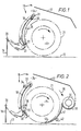
- Figure 1 is a diagrammatic side view of apparatus for picking up and conveying cut crop, embodying the invention, and shows a movable curved hood in front of and partly above a rotor;
- Figure 2 is a diagrammatic side view of a further apparatus embodying the invention for picking up cut crop, and also shows means for returning to the main crop stream any stray crop which falls from the main output stream of a pick-up rotor;
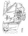
- Figs. 3 and 3(a) are perspective views from the front and side respectively of a further embodiment of the invention for picking up cut crop and shows a movable curved hood in front of and partly above a rotor;
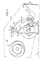
- Fig. 4 is a diagrammatic side view of the apparatus shown in Figs. 3 and 3(a); and
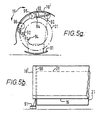
- Figs. 5(a) and 5(b) are diagrammatic side and front views respectively of a further modification of a crop pick up apparatus embodying the invention.
- There is shown a crop pick-up apparatus comprising a
rotor 11 mounted on a mobile main frame (not shown) for movement over theground 13 to pick-up previously cut crop. A hood assembly or rotor housing is indicated generally at 15, and includes an overhead baffle ordeflector 17. There is also provided a freely-hanging,stiff curtain member 19 suspended from atransverse pivot bar 20. - The
rotor 11 preferably consists of a plurality of stiff resilient outwardly directed crop engaging elements, the outer periphery of which is indicated by abroken line 21. Conveniently therotor 11 comprises a pick-up rotor as disclosed in one of our published UK Patent Application No. 2075816A, 2099272A and 2107963A. Therotor 11 is rotated in a clockwise direction so as to pick-up cut crop from the ground and to convey the crop upwardly and rearwardly over therotor 11. - The crop material is conveyed upwardly and to the rear of the apparatus beneath the baffle or
deflector 17 above the rotor. Thedeflector 17 may be a flat or curved plate. The gap shown and indicated at 24 allows the operator to see the crop stream to check operation, and also facilitates, if desirable, the introduction and even distribution of additives in liquid or solid form. - The
protective curtain 19 is suspended from therigid bar 20 preceding therotor 11. Thecurtain 19 serves the additional purpose of guiding the crop. Thecurtain 19 is shown in its rest position in full lines, and in broken lines there is shown the normal deflected position of thecurtain 19 during forward movement of the apparatus over crop. - In Figure 1, a
hood 18 withside flanges 29 is shown to be located byspigots 22 in lowerarcuate slots 23, and byspigots 30 in upperlinear slots 31. The extreme position to which thehood member 18 can be moved in response to increased crop pressure is shown in broken lines. It will be seen that the upper clearance of thehood 18 from therotor 11, and also the angle of thehood 18, have changed with movement of thehood 18 from the full line to the broken line positions, in addition to the change brought about at the lower end of thehood 18. By selecting differing shapes, angles and lengths of slots, a range of effects may be achieved in the movement of thehood 18. Again, spring loading of thehood 18 to increase or decrease its resistance to deflection, may be provided. Forrotors 11 which are intended to treat the crop, for example by conditioning the crop, a transverse cracking bar may be provided at the lower portion of thehood 18; the bar may be continuous or may provide an intermittent edge. - Figure 2 shows a further modification of the apparatus described thus far, and discloses firstly a modification of the mounting for the
hood 18 of Figure 1. In Figure 2 thehood 18 is shown to be suspended and pivoted on upper andlower link arms 32 and 33 which are pivoted respectively at fixed pivot points 34 and 35 which are fixed relative to the main frame (not shown). The upper andlower link arms 32 and 33 are so dimensioned and angled that, by way of example, the upper end of thehood 18 moves slightly further away from theperiphery 21 of therotor 11 than does the lower end of thehood 18, during movement of thehood 18 from the full line position to the broken line position shown. Also by way of example, thehood 18 is shown to be spring loaded to increase its resistance to deflection, the spring loading being shown diagrammatically at 36. - It should be appreciated that other forms of hood suspension may be used, including suspensions consisting mainly or entirely of springs or elastomeric elements, to make the hood responsive to changes of load. Elastic links allow additional lateral differentiation in the response to different crop loads.
- Figure 2 also illustrates a feature concerned with the collection of stray pieces of crop which may escape from the main stream of crop leaving the pick-up rotor. To the rear of the pick-up
rotor 11 there is shown atransverse auger 37 which has beneath it a conventionalconcave trough 38. The main crop stream may will leave therotor 11 generally along the direction indicated diagrammatically by thearrow 39, but some stray pieces of crop will fall downwardly with the rotatingrotor 11 and would normally fall to the ground in a region indicated diagrammatically at 40. However, in the embodiment of Figure 2 there is provided a furtherconcave guide member 41 which leads around, and is spaced from the underside of therotor 11. Theguide member 41 leads from the forward edge of thetrough 38 and terminates just rearwardly of the bottom dead centre position of therotor 11. A supportingmember 42 is positioned to the rear of theguide member 41. Theguide member 41 collects stray pieces of crop material and forces them to be guided downwardly and forwardly by therotor 11 to be re-introduced into the crop layer in front of therotor 11. For minimum stubble resistance, theguide member 41 may be sharpened at its lower leading edge 43. Thesupport member 42 behind theguide member 41 maintains theguide member 41 in fixed relationship with therotor 11. - There will now be described with reference to Figures 3, 3a and 4 a further embodiment of the invention which corresponds generally to the embodiments shown in Figures 1 and 2, and consists of a crop pick-up apparatus which has been found of particular advantage in practice.
- The general main frame of the apparatus is referred to by the numeral 50, and a pick-up
rotor 11 is mounted betweensubstantial side plates 51 of theframe 50 and is driven from thepto 52 of a tractor through a conventional drive linkage terminating at 53 (Figure 3). Therotor 11 is formed of a brush-like structure as set out in our previous published UK Patent Application No. 2075816A, although the crop engaging elements need not necessarily be multi-filamented brush tufts but can be of alternative construction (including a one-piece construction) and can be made from flexible material or resiliently mounted rigid material, and in such cases are preferably shaped to be tapering towards their crop engaging tips, to assist crop detachment and transfer into, for example, a forage harvester feed mechanism. - Referring to Figures 3 and 3(a) a
curved hood 54 extends over the front of therotor 11, and in the paticular example shown is formed of transparent synthetic plastics material, which allows an operator of the apparatus to view the operation of the rotor. Referring to Figure 3(a), thehood 54 is mounted by two pivotedarms side plate 51 of themain frame 50, and corresponding pivoted arms are provided on the other side of the apparatus. Thepivot arm 55 is pivoted to thehood 54 at apivot 57, and to theside plate 51 at apivot 59, and thearm 56 is correspondingly pivoted atpivots pivot point 60 to be moved relative to theside plate 51. - The main structure is completed by
side panels 61 and side skids 62, repeated on the other side of the apparatus. - In Figure 3, the
hood 54 is shown at its lowermost and most forward position, and the hood is shown at this position in Figure 4 in full lines. Thehood 54 is movable by pivoting on thearms pivots slots side panels 61 of the apparatus, of which one is shown in Figure 3(a). Theside panels 61 are held in frames havinghorizontal cross members hood 64 is limited bystops arm 56, and bearing against thecross member device 68 is linked by an arm 69 to theside frame 51, and biases the hood into the forward and downward position by the effect of thespring 70 acting between the base of the biasing means 68 and the link 69. The apparatus is supported onskids 62 of which one is shown in Figure 3(a) secured to theside plate 51. - As shown in Figure 4, in operation crop is picked up by the
rotor 11 and lifted upwardly and rearwardly over therotor 11 in the direction of thearrow 39 and is fed to anauger 71 which feeds the crop towards a conventional chopping mechanism of a forage harvester, indicated generally at 72 in Figure 3. As has been explained previously, where the crop load is light, thehood 54 will be in its forward and lower position, but where the crop is heavier, either with a greater bulk or higher friction, or a combination of both, thehood 54 will rise upwardly and rearwardly to allow greater clearances in the crop passage between thehood 54 and therotor 11. - In Figure 5(a) and 5(b) there are shown in diagrammatic side cross section and front view respectively a pick-up rotor for picking up crop on the ground, and embodying the invention.
Side plates 90 attached to aground skid 91 on each side of the apparatus are shaped at the top to support a rotor hood 16' which laterally overhangs theside plates 90. The hood 16' is secured only by two ormore springs 92 and 93 which are shown diagrammatically coupled between the hood 16' and securingportions 94 of theside plates 90. The directional pull of thesprings 92 and 93 is arranged to be downwardly and forwardly at the front against limit stops (not shown) and towards the rotor centre against resilient buffers (also not shown) which prevent noise arising from metal-to-metal contact. Small rubber wheels orrollers side plates 90. Thus the hood 16' is free to respond to varying crop loads by lifting at one side or both sides as far around the covered rotor periphery as the load dictates. The springs and their direction of fitting shown are merely an example, and it should be noted that compression or tension springs can be used, including telescopic spring loaded arms. It should also be noted that the rotor hood 16' may have one or more transverse hinges (not shown) which, in combination with the springs arranged to act near the hinges axes, to give maximum freedom of response. - With reference to Figures 5(a) and (b), there is provided in essence, a rotor cover which is wider than the lateral spacing of the rotor housing side plates, so that the upper edges of the side plates form the lower limit stops and movement of the housing above the side plates can correspond to the extension of independent elastic links in a non-predetermined path. Advantageously rollers or wheels attached near the upper ends of the side plates support and guide the overhanging rotor cover and minimise sliding friction. The rollers or wheels may be made from resilient material to cushion the return movement of the rotor housing.
- It is to be appreciated that where there is provided a resiliently suspended hood or rotor cover, there can be a difference in one or other of the horizontal and vertical clearance from one side of the side of the hood to the other transversely across the machine.
- Various references are made in this specification to variations in crop load. By the term crop load is meant the amount and/or the nature of the crop picked up and conveyed by the rotor. For example the crop load may be increased by an increase in the amount of crop conveyed by the rotor, or by an increase in the friction exerted by the crop conveyed by the rotor, or by both factors. Friction may be increased for example by an increase in wetness of the crop.
Claims (15)
Applications Claiming Priority (2)
| Application Number | Priority Date | Filing Date | Title |
|---|---|---|---|
| GB8221910 | 1982-07-29 | ||
| GB8221910 | 1982-07-29 |
Publications (3)
| Publication Number | Publication Date |
|---|---|
| EP0100628A1 EP0100628A1 (en) | 1984-02-15 |
| EP0100628B1 EP0100628B1 (en) | 1987-01-07 |
| EP0100628B2 true EP0100628B2 (en) | 1991-01-23 |
Family
ID=10531983
Family Applications (1)
| Application Number | Title | Priority Date | Filing Date |
|---|---|---|---|
| EP19830304221 Expired EP0100628B2 (en) | 1982-07-29 | 1983-07-20 | Apparatus and method for picking up and conveying crop |
Country Status (4)
| Country | Link |
|---|---|
| EP (1) | EP0100628B2 (en) |
| DE (1) | DE3368850D1 (en) |
| DK (1) | DK343983A (en) |
| GB (1) | GB2124876B (en) |
Families Citing this family (11)
| Publication number | Priority date | Publication date | Assignee | Title |
|---|---|---|---|---|
| DE3320717A1 (en) * | 1983-06-08 | 1984-12-13 | Klöckner-Humboldt-Deutz AG Zweigniederlassung Fahr, 7702 Gottmadingen | FEED PROCESSING MACHINE |
| DE3577637D1 (en) * | 1984-02-14 | 1990-06-21 | Nat Res Dev | DEVICE FOR RECEIVING AND PROMOTING HARVEST OR OTHER MATERIAL. |
| NL1006550C2 (en) * | 1997-07-11 | 1999-01-12 | Greenland Nieuw Vennep Bv | Crop harvesting machine with a bruising plate |
| FR2767633B1 (en) * | 1997-09-02 | 1999-10-08 | Kuhn Sa | IMPROVED CONDITIONING DEVICE, CONDITIONING MACHINE AND MOWER CONDITIONER COMPRISING SUCH A DEVICE |
| DE19826976A1 (en) * | 1998-06-18 | 1999-12-23 | Niemeyer Landmasch Gmbh | Conditioner for rotary mowers |
| GB9903624D0 (en) | 1999-02-18 | 1999-04-07 | Ford New Holland Nv | Movable windguard |
| FR2822642B1 (en) * | 2001-03-30 | 2005-03-04 | Roquette Freres | FOOD DENREE WITH PROLONGED ENERGY RELEASE |
| DE10120124C2 (en) * | 2001-04-25 | 2003-04-30 | Krone Bernhard Gmbh Maschf | Agricultural harvester |
| US6688092B2 (en) * | 2002-01-14 | 2004-02-10 | Deere & Company | Pick-up crop baffle including integral crop hold down rods and suspension for use in widely varied crops |
| DE102016108191A1 (en) * | 2016-05-03 | 2017-11-09 | Usines Claas France S.A.S. | Harvester with a crop picking device |
| GB2560997A (en) | 2017-03-31 | 2018-10-03 | Kverneland Group Kerteminde As | Dual conditioner plate |
Family Cites Families (5)
| Publication number | Priority date | Publication date | Assignee | Title |
|---|---|---|---|---|
| GB1214840A (en) * | 1967-01-13 | 1970-12-02 | Landbouwwerktuigen & Maschf | Improvements in mowing machines |
| CH530751A (en) * | 1970-10-23 | 1972-11-30 | Bucher Guyer Ag Masch | Mobile grass conditioning machine |
| US4182099A (en) * | 1977-11-21 | 1980-01-08 | Deere & Company | Impeller mower-conditioner rotor |
| US4233803A (en) * | 1978-05-04 | 1980-11-18 | Deere & Company | Adjustable conditioning plate for an impeller mower-conditioner |
| DK214682A (en) * | 1981-05-15 | 1982-11-16 | Nat Res Dev | METHOD AND APPLICATION FOR CROP TREATMENT |
-
1983
- 1983-07-20 DE DE8383304221T patent/DE3368850D1/en not_active Expired
- 1983-07-20 GB GB08319582A patent/GB2124876B/en not_active Expired
- 1983-07-20 EP EP19830304221 patent/EP0100628B2/en not_active Expired
- 1983-07-27 DK DK343983A patent/DK343983A/en not_active Application Discontinuation
Also Published As
| Publication number | Publication date |
|---|---|
| GB2124876B (en) | 1986-05-21 |
| DE3368850D1 (en) | 1987-02-12 |
| EP0100628B1 (en) | 1987-01-07 |
| GB8319582D0 (en) | 1983-08-24 |
| EP0100628A1 (en) | 1984-02-15 |
| DK343983A (en) | 1984-01-30 |
| DK343983D0 (en) | 1983-07-27 |
| GB2124876A (en) | 1984-02-29 |
Similar Documents
| Publication | Publication Date | Title |
|---|---|---|
| US4539798A (en) | Apparatus and method for conveying and/or treating crop | |
| CA1105272A (en) | Crop harvesting machine header suspension system | |
| US4414793A (en) | Flexible crop harvesting header | |
| EP0100628B2 (en) | Apparatus and method for picking up and conveying crop | |
| US4479347A (en) | Loading vehicle for picking up and transporting straw material | |
| EP3466241B1 (en) | Agricultural harvesting head with float arm pivots below reciprocating knives | |
| US4218865A (en) | Agricultural machines | |
| CA2521187C (en) | Conveyor for a windrower | |
| US5109657A (en) | Receiving system for a berry harvester | |
| CA1129212A (en) | Gatherer sheet arrangement for a row crop harvesting header | |
| US5375403A (en) | Lowbush berry harvester | |
| US3517491A (en) | Header suspension mounting for pull-type harvesters | |
| US5351468A (en) | Selectable windrowing mower attachment and method of mounting | |
| US4287707A (en) | Harvesters | |
| US6244026B1 (en) | Crop lifter mechanism | |
| CA1233647A (en) | Snow trap attachment for crop harvesting machine | |
| EP0872171B1 (en) | Feeder means for a forage harvester | |
| US4574567A (en) | Harvesters | |
| EP0439991A1 (en) | A side discharger for a windrower | |
| US4149361A (en) | Crop stubble masher for harvesting machine | |
| US3514937A (en) | Crop pickup mechanism | |
| US4783952A (en) | Harvesters | |
| US3577715A (en) | Suspension for mounting a header on a tractor | |
| US4362006A (en) | Horizontally rotating blade-type conditioning device for swathers | |
| US4288970A (en) | Asparagus harvester |
Legal Events
| Date | Code | Title | Description |
|---|---|---|---|
| PUAI | Public reference made under article 153(3) epc to a published international application that has entered the european phase |
Free format text: ORIGINAL CODE: 0009012 |
|
| AK | Designated contracting states |
Designated state(s): DE FR IT NL |
|
| 17P | Request for examination filed |
Effective date: 19840305 |
|
| ITF | It: translation for a ep patent filed |
Owner name: BARZANO' E ZANARDO ROMA S.P.A. |
|
| GRAA | (expected) grant |
Free format text: ORIGINAL CODE: 0009210 |
|
| AK | Designated contracting states |
Kind code of ref document: B1 Designated state(s): DE FR IT NL |
|
| ET | Fr: translation filed | ||
| REF | Corresponds to: |
Ref document number: 3368850 Country of ref document: DE Date of ref document: 19870212 |
|
| PLBE | No opposition filed within time limit |
Free format text: ORIGINAL CODE: 0009261 |
|
| PLBI | Opposition filed |
Free format text: ORIGINAL CODE: 0009260 |
|
| 26N | No opposition filed | ||
| 26 | Opposition filed |
Opponent name: C. VAN DER LELY N.V. Effective date: 19871001 |
|
| NLR1 | Nl: opposition has been filed with the epo |
Opponent name: C.VAN DER LELY N.V. |
|
| PLAA | Information modified related to event that no opposition was filed |
Free format text: ORIGINAL CODE: 0009299DELT |
|
| PLAB | Opposition data, opponent's data or that of the opponent's representative modified |
Free format text: ORIGINAL CODE: 0009299OPPO |
|
| R26 | Opposition filed (corrected) |
Opponent name: C. VAN DER LELY N.V. Effective date: 19871001 |
|
| PLAB | Opposition data, opponent's data or that of the opponent's representative modified |
Free format text: ORIGINAL CODE: 0009299OPPO |
|
| R26 | Opposition filed (corrected) |
Opponent name: C. VAN DER LELY N.V. Effective date: 19871001 |
|
| PUAH | Patent maintained in amended form |
Free format text: ORIGINAL CODE: 0009272 |
|
| STAA | Information on the status of an ep patent application or granted ep patent |
Free format text: STATUS: PATENT MAINTAINED AS AMENDED |
|
| ITF | It: translation for a ep patent filed |
Owner name: BARZANO' E ZANARDO ROMA S.P.A. |
|
| 27A | Patent maintained in amended form |
Effective date: 19910123 |
|
| AK | Designated contracting states |
Kind code of ref document: B2 Designated state(s): DE FR IT NL |
|
| NLR2 | Nl: decision of opposition | ||
| NLR3 | Nl: receipt of modified translations in the netherlands language after an opposition procedure | ||
| ET3 | Fr: translation filed ** decision concerning opposition | ||
| ITPR | It: changes in ownership of a european patent |
Owner name: CESSIONE;BRITISH TECHNOLOGY GROUP LIMITED |
|
| REG | Reference to a national code |
Ref country code: FR Ref legal event code: TP |
|
| NLS | Nl: assignments of ep-patents |
Owner name: BRITISH TECHNOLOGY GROUP LTD TE LONDEN, GROOT-BRIT |
|
| ITTA | It: last paid annual fee | ||
| PGFP | Annual fee paid to national office [announced via postgrant information from national office to epo] |
Ref country code: FR Payment date: 19960627 Year of fee payment: 14 |
|
| PGFP | Annual fee paid to national office [announced via postgrant information from national office to epo] |
Ref country code: NL Payment date: 19960731 Year of fee payment: 14 |
|
| PGFP | Annual fee paid to national office [announced via postgrant information from national office to epo] |
Ref country code: DE Payment date: 19960927 Year of fee payment: 14 |
|
| PG25 | Lapsed in a contracting state [announced via postgrant information from national office to epo] |
Ref country code: NL Free format text: LAPSE BECAUSE OF NON-PAYMENT OF DUE FEES Effective date: 19980201 |
|
| PG25 | Lapsed in a contracting state [announced via postgrant information from national office to epo] |
Ref country code: FR Free format text: LAPSE BECAUSE OF NON-PAYMENT OF DUE FEES Effective date: 19980331 |
|
| NLV4 | Nl: lapsed or anulled due to non-payment of the annual fee |
Effective date: 19980201 |
|
| PG25 | Lapsed in a contracting state [announced via postgrant information from national office to epo] |
Ref country code: DE Free format text: LAPSE BECAUSE OF NON-PAYMENT OF DUE FEES Effective date: 19980401 |
|
| REG | Reference to a national code |
Ref country code: FR Ref legal event code: ST |