EP0872153B1 - Micromechanical microphone - Google Patents
Micromechanical microphone Download PDFInfo
- Publication number
- EP0872153B1 EP0872153B1 EP96921908A EP96921908A EP0872153B1 EP 0872153 B1 EP0872153 B1 EP 0872153B1 EP 96921908 A EP96921908 A EP 96921908A EP 96921908 A EP96921908 A EP 96921908A EP 0872153 B1 EP0872153 B1 EP 0872153B1
- Authority
- EP
- European Patent Office
- Prior art keywords
- membranes
- microphone
- transducer element
- membrane
- pressure
- Prior art date
- Legal status (The legal status is an assumption and is not a legal conclusion. Google has not performed a legal analysis and makes no representation as to the accuracy of the status listed.)
- Expired - Lifetime
Links
- 238000007789 sealing Methods 0.000 claims abstract description 13
- 239000012528 membrane Substances 0.000 claims description 96
- 230000002093 peripheral effect Effects 0.000 claims description 12
- 239000000428 dust Substances 0.000 abstract description 5
- 230000003068 static effect Effects 0.000 description 24
- 230000035945 sensitivity Effects 0.000 description 15
- 230000008859 change Effects 0.000 description 10
- 238000004519 manufacturing process Methods 0.000 description 8
- 239000000463 material Substances 0.000 description 8
- 238000010276 construction Methods 0.000 description 6
- 238000005516 engineering process Methods 0.000 description 3
- 239000011148 porous material Substances 0.000 description 3
- XLYOFNOQVPJJNP-UHFFFAOYSA-N water Substances O XLYOFNOQVPJJNP-UHFFFAOYSA-N 0.000 description 3
- XUIMIQQOPSSXEZ-UHFFFAOYSA-N Silicon Chemical compound [Si] XUIMIQQOPSSXEZ-UHFFFAOYSA-N 0.000 description 2
- 230000008901 benefit Effects 0.000 description 2
- 238000013016 damping Methods 0.000 description 2
- 230000000694 effects Effects 0.000 description 2
- 229910052710 silicon Inorganic materials 0.000 description 2
- 239000010703 silicon Substances 0.000 description 2
- 238000009423 ventilation Methods 0.000 description 2
- 229920000544 Gore-Tex Polymers 0.000 description 1
- 239000004809 Teflon Substances 0.000 description 1
- 229920006362 Teflon® Polymers 0.000 description 1
- 238000009530 blood pressure measurement Methods 0.000 description 1
- 238000000576 coating method Methods 0.000 description 1
- 230000007423 decrease Effects 0.000 description 1
- 238000013461 design Methods 0.000 description 1
- 238000001514 detection method Methods 0.000 description 1
- 238000009792 diffusion process Methods 0.000 description 1
- 238000005538 encapsulation Methods 0.000 description 1
- 238000011156 evaluation Methods 0.000 description 1
- 239000011888 foil Substances 0.000 description 1
- 230000006870 function Effects 0.000 description 1
- 230000006872 improvement Effects 0.000 description 1
- 230000010354 integration Effects 0.000 description 1
- 239000002184 metal Substances 0.000 description 1
- 238000000034 method Methods 0.000 description 1
- 239000002245 particle Substances 0.000 description 1
- 239000004033 plastic Substances 0.000 description 1
- 230000008569 process Effects 0.000 description 1
- 238000012552 review Methods 0.000 description 1
Images
Classifications
-
- H—ELECTRICITY
- H04—ELECTRIC COMMUNICATION TECHNIQUE
- H04R—LOUDSPEAKERS, MICROPHONES, GRAMOPHONE PICK-UPS OR LIKE ACOUSTIC ELECTROMECHANICAL TRANSDUCERS; DEAF-AID SETS; PUBLIC ADDRESS SYSTEMS
- H04R19/00—Electrostatic transducers
- H04R19/04—Microphones
Definitions
- the present invention concerns a micromechanical microphone with a housing in which a transducer element is placed, and which has a sound inlet on one side of the transducer element and a pressure equalisation hole on the other side.
- the pressure equalisation hole has a high acoustic impedance at audio frequencies, and is placed in a, in other respects, closed rear chamber.
- the transducer element normally consists of a membrane which deflects due to the sound pressure, and an arrangement to convert this deflection into an electrical signal.
- microphones of small dimensions as of the magnitude 3.5 mm x 3.5 mm x 2 mm, for example for use in hearing aids, are traditionally manufactured by assembling a number of individual parts, such as plastic foils, metal parts, hybrid pre-amplifiers etc., in total 12-15 parts.
- DE 2 831 401 discloses a microphone having a transducer element in a housing with a sound inlet and a pressure equalisation hole on respective sides of the transducer element.
- the transducer element has a fixed, electrically conductive electrode and a single electrically conductive sealing membrane.
- US 3 980 838 discloses an electroacoustic transducer designed for use as a speaker.
- the transducer has an electrode with through-going openings and an acoustically active membrane on either side.
- US 5 085 070 discloses the principle of force balancing feedback whereby the sensitivity and the signal-to-noise ratio of a microphone are increased.
- the membrane's centre deflection is for example more than twice as large as the height of the encapsulated volume multiplied by the relative pressure change and even bigger if the area of the membrane is smaller than the rear chambers sectional area.
- Static pressure variations of ⁇ 10% are not unrealistic, meaning that the membrane's static deflection can be in the range of 0,5 mm at a height of 2 mm. In a micromechanical microphone this is unacceptable.
- deflections of this magnitude consume far too much space, meaning that the microphone becomes significant bigger than necessary and desirable.
- it requires a very soft membrane material to keep the membrane acoustically transparent under such large static deflections. It may not be impossible to find a material that meets these requirements, but if it should be compatible with a micromechanical production process, it limits the possibilities drastically, meaning a far more complicated production process is needed.
- the purpose of the present invention is to solve the above discussed problems and, according to the invention, this is obtained by the presence of a sealing acoustic transparent membrane on each side of the transducer element in a distance less than 50 ⁇ m from this.
- the pressure in the sealed volume may therefore be considered equivalent to the atmospheric pressure outside. This means, that if the temperature and/or the static pressure (the atmospheric pressure) is changing, the encapsulated volume must change proportionally, to satisfy expression (1).
- the relative change of the encapsulated volume will be: ⁇ V ⁇ Vo ⁇ ⁇ T To - ⁇ p po where initial pressure, temperature and volume are notified by index o, and the increase is notified with ⁇ .
- the absolute change in volume ⁇ V and thereby the membrane deflection must be very large.
- the encapsulated volume becomes smaller and therefore requires a smaller absolute volume change and thereby a small membrane deflection. If e.g. maximum deflections in the size of 50 ⁇ m are allowed at a pressure change of 50.000 Pa, the distance between the transducer element and the sealed membranes must be max. 50 ⁇ m, as the air volume in the transducer element is considered negligible.
- the initial pressure and the gas in the chamber between the sealed membranes can be controlled according to the invention, which advantageously can be obtained by use of micromechanics in the production process.
- the gas must, of course, contain an absolute minimum of water vapour.
- the suggested microphone is not limited to an exact type of transducer element and can as such e.g. be a capacitive transducer element with external bias, an electret based transducer element or a tunnel current based transducer element of which all typically would have a membrane as a part of the transducer element.
- the two sealed membranes are mechanically connected and electrically conductive or provided with an electrically conductive layer.
- the transducer element is in this embodiment provided with a fixed conductive electrode, which together with the two sealed membranes, directly makes a capacitive microphone.
- the mechanical connection between the membranes serves in reducing the effects of changes in the static pressure on the microphones sensitivity for the sound pressure.
- connection between the membranes constitutes, according to the invention, appropriately of piles which can be wider than they are high and which pass freely through the holes in the fixed electrode between the membranes.
- the peripheral areas of the sealed membranes have no mechanical interconnection by means of piles. These peripheral regions are hereby able to absorb the static pressure variations by means of deflection, so that the sealed volume and therewith the pressure in it, changes.
- the deflection of the central area of the membranes becomes very small due to the piles.
- only the central areas of the sealed membranes are electrically conductive.
- the conductive central areas of the sealed membranes are thicker and stiffer than the peripheral regions. This adds further to making the microphone's sensitivity independent of the static pressure.
- the fixed electrode may have cut-outs in the peripheral areas.
- the membrane may be electrically conducting all over, but the signal comes only from the central region where the fixed centre electrode is.
- the transducer element can include a membrane and two fixed conductive back plates with through holes, placed on either side of the membrane.
- This construction features significant sensitivity for the sound pressure, meaning that in spite of the small size, a significant electrical signal may be achieved. It may be convenient to provide the membrane with a small hole for pressure equalisation as it would make a strictly symmetric construction unnecessary. The hole must be so small that it has a high acoustic impedance in the audio frequency range.
- a further improvement of the microphones characteristics can be achieved according to the invention, when a so called "force-balancing" - feedback circuit counteracts the deflection of the transducer element's membrane(s), typically by means of electrostatic forces.
- capacitive transducer elements a higher sensitivity is obtained, as it is possible to work with a higher bias voltage, without the membrane will be dragged in to one of the back plates.
- This also counts for, among others, the transducer element with two membranes, which at the same time forms the sealing with a fixed electrode in between and for the transducer element consisting of a membrane and two back plates.
- the force-balancing can, as a matter of fact, also by most types of transducer elements imply other advantages, such as an increased bandwidth and better linearity of the microphone, and a reduced sensitivity to variations in the membrane's and the rear chamber's stiffness.
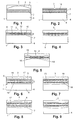
- the microphone shown in fig. 1 has a housing 1, in which a transducer element 2 is placed, and which has a sound inlet 3. Above the transducer element 2, there is a front chamber 9 in which a sealing membrane 5 is placed , which primarily is acoustic transparent, with a compliance that does not influence the sound pressure. Below the transducer element 2 there is a hermetically closed rear chamber 8. The microphone is shown at a static pressure change at 20 %, which has caused the membrane deflect strongly, so the volume change of the hermetic sealed chamber mostly neutralises the change in the static pressure, as the pressure in the sealed chamber falls when the volume increases. It is clear that this construction requires a front chamber of significant size in order to allow room for the large deflection of the membrane.
- the rear chamber 8 is provided with an air ventilation hole or pressure equalisation hole 4, and above the transducer element 2 a sealing acoustic transparent membrane 6 is placed, and under the transducer element a similar sealing and acoustic transparent membrane 7 is placed.
- the membranes 6 and 7 are placed closely to the transducer element, by which means the encapsulated volume between the membranes becomes much smaller than if the whole rear chamber 8 is included in the sealed volume.
- the necessary deflections of the membranes are thereby also becoming proportionally smaller. In this context it should be mentioned, that large deflections will stretch the membranes which makes them stiffer and this, again, causes that the membranes become less acoustic transparent. With the construction shown in fig. 2 this disadvantage is strongly reduced or even totally avoided.
- the transducer element 2 consists of a fixed conductive electrode 10 and two sealed membranes 6 and 7, which are connected with each other by means of connection piles 11, which pass through the holes 12 in the electrode 10.
- the sealed membranes 6 and 7 are in their central area 13 and 14 electrically conductive, as they as an example are provided with electrically conductive coatings by which means the membranes together with the electrode 10 forms a capacitive microphone where the rear chamber 8 which like in the embodiment in fig. 2 is provided with a pressure equalisation hole 4.
- the mechanical connection which is established by means of the piles 11, which are not touching the centre electrode 10 in the holes 12, serves to reduce the influence of static pressure changes on the microphones sensitivity for the outside coming sound pressure.
- This can be used for defining the condenser area, if the membranes are conductive all over, and the area is not definable by means of electrodes on the membranes. Furthermore it can be used in order to obtain a lower damping and a higher sensitivity.
- a transducer element 2 In a housing 1 a transducer element 2 is placed and the housing has a sound inlet 3 and a pressure equalisation hole 4 and sealed acoustic transparent membranes 6 and 7 are placed in a front chamber 9 and a rear chamber 8 respectively.
- the transducer element In order to obtain a high sensitivity, the transducer element is provided with two back plates 17 and 18 placed one on each side of a membrane 19, which is deflected by the sound pressure. By using two back plates for capacitive detection a doubled sensitivity is obtained compared to the case of only using one back plate.
- fig. 6 this microphone embodiment is shown without any pressures acting, while fig. 7 shows the microphone being exposed for a sound pressure through the sound inlet 3.
- Fig. 8 shows the microphone being exposed for a static pressure, according to the embodiment shown in fig. 5.
- fig. 9 shows the microphone as it, at the same time, is exposed for a sound pressure and a static pressure.
- the transducer element referred to above shown in fig. 2-5 with a conductive centre electrode 10 and two membranes 6 and 7, one on each side of 10 and the transducer element shown in fig. 6-9 with a membrane 19 and two back plates 17 and 18, in a simply way, makes it possible to realise a feedback loop which enables "force-balancing" by which the membrane or the membranes are under influence of electronically controlled forces, which ideally counterbalances the acoustic pressure on it/them, so that it/they are kept in it's/their equilibrium position. This reduces the sensitivity for variations in stiffness of the rear chamber 8, which is depending on the static pressure, and in the stiffness of the membrane or membranes. For example by the microphone embodiment in fig.
- the force-balancing feedback circuit can be built as a ⁇ -converter (sigma-delta converter).
- the microphone may in that case be a part of the converter, as it may perform two integrations. These can be realised by the microphone's second order slope observed at frequencies higher than the resonance frequency, where the microphone roughly acts as a double integrator.
- the miniature sized microphones described in this context for use in hearing aids operate at battery voltages in the order of 1 V.
- a very small air gap distance (below 1 ⁇ m), between the transducer elements membrane(s) 6 and 7 accordingly 19 and back plate(s) 10 accordingly 17 and 18 is required.
- the air gap should be about max. 0,5 ⁇ m, to make it possible to counterbalance a sound pressure of 10 Pa by means of a voltage of 1 V. Air gaps that small are today only possible to realise by means of micromechanics.
- the air gap When the air gap is that small it is necessary to provide the back plates with a very big amount of air holes 12 respectively 20 in order to avoid that the air flow in the air gap presents a too big acoustic resistance.
- the distance between the holes may be less than 10 ⁇ m, which is feasible by means or micromechanics, but difficult with traditional technology. This means, it is necessary to have very small air gaps and holes, which, however, makes the microphones sensitive to dust and humidity and therefore, necessitates sealing.
Landscapes
- Physics & Mathematics (AREA)
- Engineering & Computer Science (AREA)
- Acoustics & Sound (AREA)
- Signal Processing (AREA)
- Electrostatic, Electromagnetic, Magneto- Strictive, And Variable-Resistance Transducers (AREA)
- Piezo-Electric Transducers For Audible Bands (AREA)
- Laminated Bodies (AREA)
- Obtaining Desirable Characteristics In Audible-Bandwidth Transducers (AREA)
Applications Claiming Priority (3)
| Application Number | Priority Date | Filing Date | Title |
|---|---|---|---|
| DK072695A DK172085B1 (da) | 1995-06-23 | 1995-06-23 | Mikromekanisk mikrofon |
| DK72695 | 1995-06-23 | ||
| PCT/DK1996/000276 WO1997001258A1 (en) | 1995-06-23 | 1996-06-21 | Micromechanical microphone |
Publications (2)
| Publication Number | Publication Date |
|---|---|
| EP0872153A1 EP0872153A1 (en) | 1998-10-21 |
| EP0872153B1 true EP0872153B1 (en) | 2001-09-05 |
Family
ID=8096839
Family Applications (1)
| Application Number | Title | Priority Date | Filing Date |
|---|---|---|---|
| EP96921908A Expired - Lifetime EP0872153B1 (en) | 1995-06-23 | 1996-06-21 | Micromechanical microphone |
Country Status (8)
| Country | Link |
|---|---|
| US (1) | US6075867A (enExample) |
| EP (1) | EP0872153B1 (enExample) |
| JP (1) | JPH11508101A (enExample) |
| AT (1) | ATE205355T1 (enExample) |
| DE (1) | DE69615056T2 (enExample) |
| DK (2) | DK172085B1 (enExample) |
| ES (1) | ES2159747T3 (enExample) |
| WO (1) | WO1997001258A1 (enExample) |
Families Citing this family (73)
| Publication number | Priority date | Publication date | Assignee | Title |
|---|---|---|---|---|
| FR1318783A (fr) * | 1962-01-12 | 1963-02-22 | Dispositif de sécurité pour le blocage des portes | |
| US7881486B1 (en) * | 1996-12-31 | 2011-02-01 | Etymotic Research, Inc. | Directional microphone assembly |
| DE19715365C2 (de) * | 1997-04-11 | 1999-03-25 | Sennheiser Electronic | Kondensatormikrofon |
| US6088463A (en) | 1998-10-30 | 2000-07-11 | Microtronic A/S | Solid state silicon-based condenser microphone |
| US7003127B1 (en) | 1999-01-07 | 2006-02-21 | Sarnoff Corporation | Hearing aid with large diaphragm microphone element including a printed circuit board |
| JP2002534933A (ja) | 1999-01-07 | 2002-10-15 | サーノフ コーポレイション | プリント回路基板を有する大型ダイアフラムマイクロフォン素子を備えた補聴器 |
| AT407322B (de) * | 1999-03-23 | 2001-02-26 | Akg Acoustics Gmbh | Klein-mikrophon |
| US6522762B1 (en) | 1999-09-07 | 2003-02-18 | Microtronic A/S | Silicon-based sensor system |
| US6505076B2 (en) * | 2000-12-08 | 2003-01-07 | Advanced Bionics Corporation | Water-resistant, wideband microphone subassembly |
| US6741709B2 (en) * | 2000-12-20 | 2004-05-25 | Shure Incorporated | Condenser microphone assembly |
| GB0113255D0 (en) * | 2001-05-31 | 2001-07-25 | Scient Generics Ltd | Number generator |
| US20070113964A1 (en) * | 2001-12-10 | 2007-05-24 | Crawford Scott A | Small water-repellant microphone having improved acoustic performance and method of constructing same |
| US20030210799A1 (en) * | 2002-05-10 | 2003-11-13 | Gabriel Kaigham J. | Multiple membrane structure and method of manufacture |
| JP2004056438A (ja) * | 2002-07-19 | 2004-02-19 | Matsushita Electric Ind Co Ltd | マイクロフォン |
| US7072482B2 (en) | 2002-09-06 | 2006-07-04 | Sonion Nederland B.V. | Microphone with improved sound inlet port |
| US7142682B2 (en) | 2002-12-20 | 2006-11-28 | Sonion Mems A/S | Silicon-based transducer for use in hearing instruments and listening devices |
| EP1629687A1 (en) * | 2003-05-15 | 2006-03-01 | Oticon A/S | Microphone with adjustable properties |
| JP4188325B2 (ja) * | 2005-02-09 | 2008-11-26 | ホシデン株式会社 | 防塵板内蔵マイクロホン |
| DE102005008512B4 (de) * | 2005-02-24 | 2016-06-23 | Epcos Ag | Elektrisches Modul mit einem MEMS-Mikrofon |
| DE102005008514B4 (de) * | 2005-02-24 | 2019-05-16 | Tdk Corporation | Mikrofonmembran und Mikrofon mit der Mikrofonmembran |
| DE102005008511B4 (de) * | 2005-02-24 | 2019-09-12 | Tdk Corporation | MEMS-Mikrofon |
| JP4863993B2 (ja) * | 2005-05-31 | 2012-01-25 | 日本碍子株式会社 | 物体の通過検出装置 |
| DE102005053767B4 (de) * | 2005-11-10 | 2014-10-30 | Epcos Ag | MEMS-Mikrofon, Verfahren zur Herstellung und Verfahren zum Einbau |
| DE102005053765B4 (de) * | 2005-11-10 | 2016-04-14 | Epcos Ag | MEMS-Package und Verfahren zur Herstellung |
| US8081783B2 (en) * | 2006-06-20 | 2011-12-20 | Industrial Technology Research Institute | Miniature acoustic transducer |
| TWI370101B (en) * | 2007-05-15 | 2012-08-11 | Ind Tech Res Inst | Package and packaging assembly of microelectromechanical sysyem microphone |
| TWI323242B (en) * | 2007-05-15 | 2010-04-11 | Ind Tech Res Inst | Package and packageing assembly of microelectromechanical system microphone |
| TWI343756B (en) * | 2009-08-10 | 2011-06-11 | Ind Tech Res Inst | Flat loudspeaker structure |
| US7832080B2 (en) * | 2007-10-11 | 2010-11-16 | Etymotic Research, Inc. | Directional microphone assembly |
| TWI336770B (en) * | 2007-11-05 | 2011-02-01 | Ind Tech Res Inst | Sensor |
| WO2009154981A2 (en) * | 2008-05-27 | 2009-12-23 | Tufts University | Mems microphone array on a chip |
| US9071910B2 (en) * | 2008-07-24 | 2015-06-30 | Cochlear Limited | Implantable microphone device |
| TWI405472B (zh) * | 2008-07-31 | 2013-08-11 | Htc Corp | 電子裝置及其電聲換能器 |
| DE102008058787B4 (de) * | 2008-11-24 | 2017-06-08 | Sennheiser Electronic Gmbh & Co. Kg | Mikrofon |
| US9247357B2 (en) | 2009-03-13 | 2016-01-26 | Cochlear Limited | DACS actuator |
| US20100303274A1 (en) * | 2009-05-18 | 2010-12-02 | William Ryan | Microphone Having Reduced Vibration Sensitivity |
| WO2011116246A1 (en) * | 2010-03-19 | 2011-09-22 | Advanced Bionics Ag | Waterproof acoustic element enclosures and apparatus including the same |
| DE102010017959A1 (de) * | 2010-04-22 | 2011-10-27 | Epcos Ag | Mikrofon mit breitem Dynamikbereich |
| EP2432249A1 (en) * | 2010-07-02 | 2012-03-21 | Knowles Electronics Asia PTE. Ltd. | Microphone |
| CN106878838B (zh) | 2011-01-18 | 2019-04-30 | 领先仿生公司 | 防潮耳机和包括防潮耳机的可植入耳蜗刺激系统 |
| DE112012005578B4 (de) * | 2012-01-05 | 2019-11-07 | Tdk Corporation | Differenzielles Mikrofon und Verfahren zum Ansteuern eines differenziellen Mikrofons |
| US8723277B2 (en) * | 2012-02-29 | 2014-05-13 | Infineon Technologies Ag | Tunable MEMS device and method of making a tunable MEMS device |
| US9002037B2 (en) | 2012-02-29 | 2015-04-07 | Infineon Technologies Ag | MEMS structure with adjustable ventilation openings |
| US8983097B2 (en) | 2012-02-29 | 2015-03-17 | Infineon Technologies Ag | Adjustable ventilation openings in MEMS structures |
| JP6426620B2 (ja) | 2012-12-18 | 2018-11-21 | Tdk株式会社 | トップポートmemsマイクロフォン及びその製造方法 |
| US9173024B2 (en) * | 2013-01-31 | 2015-10-27 | Invensense, Inc. | Noise mitigating microphone system |
| DE102013207497A1 (de) * | 2013-04-25 | 2014-11-13 | Robert Bosch Gmbh | Bauelement mit einer mikromechanischen Mikrofonstruktur |
| DE102013106353B4 (de) * | 2013-06-18 | 2018-06-28 | Tdk Corporation | Verfahren zum Aufbringen einer strukturierten Beschichtung auf ein Bauelement |
| US9181080B2 (en) | 2013-06-28 | 2015-11-10 | Infineon Technologies Ag | MEMS microphone with low pressure region between diaphragm and counter electrode |
| US9024396B2 (en) | 2013-07-12 | 2015-05-05 | Infineon Technologies Ag | Device with MEMS structure and ventilation path in support structure |
| DE102013214823A1 (de) * | 2013-07-30 | 2015-02-05 | Robert Bosch Gmbh | Mikrofonbauteil mit mindestens zwei MEMS-Mikrofonbauelementen |
| US9510107B2 (en) | 2014-03-06 | 2016-11-29 | Infineon Technologies Ag | Double diaphragm MEMS microphone without a backplate element |
| US9438979B2 (en) * | 2014-03-06 | 2016-09-06 | Infineon Technologies Ag | MEMS sensor structure for sensing pressure waves and a change in ambient pressure |
| US9494477B2 (en) | 2014-03-31 | 2016-11-15 | Infineon Technologies Ag | Dynamic pressure sensor |
| US9554207B2 (en) * | 2015-04-30 | 2017-01-24 | Shure Acquisition Holdings, Inc. | Offset cartridge microphones |
| GB2554470A (en) | 2016-09-26 | 2018-04-04 | Cirrus Logic Int Semiconductor Ltd | MEMS device and process |
| DE102017103195B4 (de) * | 2017-02-16 | 2021-04-08 | Infineon Technologies Ag | Mikroelektromechanisches Mikrofon und Herstellungsverfahren für ein Mikroelektromechanisches Mikrofon |
| WO2018178772A2 (en) | 2017-03-28 | 2018-10-04 | Nanofone Ltd. | High performance sealed-gap capacitive microphone |
| DE102017213277B4 (de) * | 2017-08-01 | 2019-08-14 | Infineon Technologies Ag | Mems-sensoren, verfahren zum bereitstellen derselben und verfahren zum betreiben eines mems-sensors |
| WO2019135204A1 (en) | 2018-01-08 | 2019-07-11 | Nanofone Limited | High performance sealed-gap capacitive microphone with various gap geometries |
| JP7410935B2 (ja) | 2018-05-24 | 2024-01-10 | ザ リサーチ ファウンデーション フォー ザ ステイト ユニバーシティー オブ ニューヨーク | 容量性センサ |
| CN112840676B (zh) | 2018-10-05 | 2022-05-03 | 美商楼氏电子有限公司 | 响应于声学信号来生成电信号的声学换能器和麦克风组件 |
| WO2020072920A1 (en) | 2018-10-05 | 2020-04-09 | Knowles Electronics, Llc | Microphone device with ingress protection |
| CN112789239A (zh) | 2018-10-05 | 2021-05-11 | 美商楼氏电子有限公司 | 形成包括褶皱的mems振膜的方法 |
| US11932533B2 (en) | 2020-12-21 | 2024-03-19 | Infineon Technologies Ag | Signal processing circuit for triple-membrane MEMS device |
| US11889283B2 (en) | 2020-12-21 | 2024-01-30 | Infineon Technologies Ag | Triple-membrane MEMS device |
| US12240748B2 (en) | 2021-03-21 | 2025-03-04 | Knowles Electronics, Llc | MEMS die and MEMS-based sensor |
| US11528546B2 (en) | 2021-04-05 | 2022-12-13 | Knowles Electronics, Llc | Sealed vacuum MEMS die |
| US11540048B2 (en) | 2021-04-16 | 2022-12-27 | Knowles Electronics, Llc | Reduced noise MEMS device with force feedback |
| US11649161B2 (en) | 2021-07-26 | 2023-05-16 | Knowles Electronics, Llc | Diaphragm assembly with non-uniform pillar distribution |
| US11772961B2 (en) | 2021-08-26 | 2023-10-03 | Knowles Electronics, Llc | MEMS device with perimeter barometric relief pierce |
| US11780726B2 (en) | 2021-11-03 | 2023-10-10 | Knowles Electronics, Llc | Dual-diaphragm assembly having center constraint |
| KR20230115058A (ko) * | 2022-01-26 | 2023-08-02 | 주식회사 디비하이텍 | 맴스 마이크로폰 구조 및 제조방법 |
Citations (1)
| Publication number | Priority date | Publication date | Assignee | Title |
|---|---|---|---|---|
| US5085070A (en) * | 1990-02-07 | 1992-02-04 | At&T Bell Laboratories | Capacitive force-balance system for measuring small forces and pressures |
Family Cites Families (4)
| Publication number | Priority date | Publication date | Assignee | Title |
|---|---|---|---|---|
| US3980838A (en) * | 1974-02-20 | 1976-09-14 | Tokyo Shibaura Electric Co., Ltd. | Plural electret electroacoustic transducer |
| FR2402374A1 (fr) * | 1977-08-30 | 1979-03-30 | Thomson Brandt | Dispositif de montage d'un microphone incorpore dans un appareil d'enregistrement sonore et appareil a microphone incorpore |
| FR2542552B1 (fr) * | 1983-03-07 | 1986-04-11 | Thomson Csf | Transducteur electroacoustique a diaphragme piezo-electrique |
| WO1995015067A1 (de) * | 1993-11-23 | 1995-06-01 | Lux Wellenhof Gabriele | Hülle für hörgeräte, damit versehene hörgeräte bzw. teile davon und hörtestvorrichtung und verfahren |
-
1995
- 1995-06-23 DK DK072695A patent/DK172085B1/da not_active IP Right Cessation
-
1996
- 1996-06-21 ES ES96921908T patent/ES2159747T3/es not_active Expired - Lifetime
- 1996-06-21 AT AT96921908T patent/ATE205355T1/de not_active IP Right Cessation
- 1996-06-21 WO PCT/DK1996/000276 patent/WO1997001258A1/en not_active Ceased
- 1996-06-21 US US08/981,714 patent/US6075867A/en not_active Expired - Lifetime
- 1996-06-21 EP EP96921908A patent/EP0872153B1/en not_active Expired - Lifetime
- 1996-06-21 DK DK96921908T patent/DK0872153T3/da active
- 1996-06-21 DE DE69615056T patent/DE69615056T2/de not_active Expired - Lifetime
- 1996-06-21 JP JP9503529A patent/JPH11508101A/ja not_active Ceased
Patent Citations (1)
| Publication number | Priority date | Publication date | Assignee | Title |
|---|---|---|---|---|
| US5085070A (en) * | 1990-02-07 | 1992-02-04 | At&T Bell Laboratories | Capacitive force-balance system for measuring small forces and pressures |
Non-Patent Citations (1)
| Title |
|---|
| SCHEEPER P R ET AL.: "A REVIEW OF SILICON MICROPHONES", SENSORS ACTUATORS A (PHYSICAL), vol. A44, no. 1, June 1994 (1994-06-01), SWITZERLAND, pages 1 - 11 * |
Also Published As
| Publication number | Publication date |
|---|---|
| EP0872153A1 (en) | 1998-10-21 |
| ATE205355T1 (de) | 2001-09-15 |
| US6075867A (en) | 2000-06-13 |
| DK0872153T3 (da) | 2001-11-19 |
| WO1997001258A1 (en) | 1997-01-09 |
| JPH11508101A (ja) | 1999-07-13 |
| DE69615056T2 (de) | 2002-04-25 |
| DE69615056D1 (de) | 2001-10-11 |
| DK172085B1 (da) | 1997-10-13 |
| DK72695A (da) | 1996-12-24 |
| ES2159747T3 (es) | 2001-10-16 |
Similar Documents
| Publication | Publication Date | Title |
|---|---|---|
| EP0872153B1 (en) | Micromechanical microphone | |
| EP1216602B1 (en) | Mems digital-to-acoustic transducer with error cancellation | |
| US7245734B2 (en) | Directional microphone | |
| US9131319B2 (en) | Component having a micromechanical microphone structure | |
| US9143870B2 (en) | Microphone system with mechanically-coupled diaphragms | |
| CN108419189B (zh) | 压电传感器 | |
| US20050254673A1 (en) | High performance MEMS thin-film teflon electret microphone | |
| Bergqvist et al. | A new condenser microphone in silicon | |
| CN115668983B (zh) | 微机电系统(mems)传声器组件 | |
| Fueldner | Microphones | |
| Bay et al. | Design of a silicon microphone with differential read-out of a sealed double parallel-plate capacitor | |
| Dehé et al. | Silicon micromachined microphone chip at Siemens | |
| Bouwstra et al. | Silicon microphones-a Danish perspective | |
| CN109218870B (zh) | 一种麦克风 | |
| Brauer et al. | Silicon microphone based on surface and bulk micromachining | |
| US5802198A (en) | Hermetically sealed condenser microphone | |
| Bay et al. | Micromachined double backplate differential capacitive microphone | |
| Yoo et al. | Development of directional mems microphone single module for high directivity and snr | |
| US20240343552A1 (en) | Microelectromechanical acoustic component | |
| US20250083947A1 (en) | Mems microphone | |
| Mohamad et al. | High sensitivity capacitive MEMS microphone with spring supported diaphragm | |
| CN115334430B (zh) | 麦克风组件、封装结构及电子设备 | |
| US20240430623A1 (en) | Diaphragmless viscosity-driven acousitic velocity-sensing microphone | |
| US20250051155A1 (en) | Acoustic module with a centered sound port | |
| US20250324202A1 (en) | Mems device |
Legal Events
| Date | Code | Title | Description |
|---|---|---|---|
| PUAI | Public reference made under article 153(3) epc to a published international application that has entered the european phase |
Free format text: ORIGINAL CODE: 0009012 |
|
| 17P | Request for examination filed |
Effective date: 19980121 |
|
| AK | Designated contracting states |
Kind code of ref document: A1 Designated state(s): AT BE CH DE DK ES FI FR GB GR IE IT LI LU MC NL PT SE |
|
| 17Q | First examination report despatched |
Effective date: 19981214 |
|
| GRAG | Despatch of communication of intention to grant |
Free format text: ORIGINAL CODE: EPIDOS AGRA |
|
| GRAG | Despatch of communication of intention to grant |
Free format text: ORIGINAL CODE: EPIDOS AGRA |
|
| GRAG | Despatch of communication of intention to grant |
Free format text: ORIGINAL CODE: EPIDOS AGRA |
|
| GRAH | Despatch of communication of intention to grant a patent |
Free format text: ORIGINAL CODE: EPIDOS IGRA |
|
| GRAH | Despatch of communication of intention to grant a patent |
Free format text: ORIGINAL CODE: EPIDOS IGRA |
|
| GRAA | (expected) grant |
Free format text: ORIGINAL CODE: 0009210 |
|
| AK | Designated contracting states |
Kind code of ref document: B1 Designated state(s): AT BE CH DE DK ES FI FR GB GR IE IT LI LU MC NL PT SE |
|
| PG25 | Lapsed in a contracting state [announced via postgrant information from national office to epo] |
Ref country code: NL Free format text: LAPSE BECAUSE OF FAILURE TO SUBMIT A TRANSLATION OF THE DESCRIPTION OR TO PAY THE FEE WITHIN THE PRESCRIBED TIME-LIMIT Effective date: 20010905 Ref country code: LI Free format text: LAPSE BECAUSE OF FAILURE TO SUBMIT A TRANSLATION OF THE DESCRIPTION OR TO PAY THE FEE WITHIN THE PRESCRIBED TIME-LIMIT Effective date: 20010905 Ref country code: FR Free format text: LAPSE BECAUSE OF FAILURE TO SUBMIT A TRANSLATION OF THE DESCRIPTION OR TO PAY THE FEE WITHIN THE PRESCRIBED TIME-LIMIT Effective date: 20010905 Ref country code: CH Free format text: LAPSE BECAUSE OF FAILURE TO SUBMIT A TRANSLATION OF THE DESCRIPTION OR TO PAY THE FEE WITHIN THE PRESCRIBED TIME-LIMIT Effective date: 20010905 Ref country code: BE Free format text: LAPSE BECAUSE OF FAILURE TO SUBMIT A TRANSLATION OF THE DESCRIPTION OR TO PAY THE FEE WITHIN THE PRESCRIBED TIME-LIMIT Effective date: 20010905 |
|
| REF | Corresponds to: |
Ref document number: 205355 Country of ref document: AT Date of ref document: 20010915 Kind code of ref document: T |
|
| REG | Reference to a national code |
Ref country code: CH Ref legal event code: EP |
|
| PG25 | Lapsed in a contracting state [announced via postgrant information from national office to epo] |
Ref country code: AT Free format text: LAPSE BECAUSE OF FAILURE TO SUBMIT A TRANSLATION OF THE DESCRIPTION OR TO PAY THE FEE WITHIN THE PRESCRIBED TIME-LIMIT Effective date: 20010919 |
|
| REF | Corresponds to: |
Ref document number: 69615056 Country of ref document: DE Date of ref document: 20011011 |
|
| REG | Reference to a national code |
Ref country code: ES Ref legal event code: FG2A Ref document number: 2159747 Country of ref document: ES Kind code of ref document: T3 |
|
| REG | Reference to a national code |
Ref country code: IE Ref legal event code: FG4D |
|
| REG | Reference to a national code |
Ref country code: DK Ref legal event code: T3 |
|
| PG25 | Lapsed in a contracting state [announced via postgrant information from national office to epo] |
Ref country code: PT Free format text: LAPSE BECAUSE OF FAILURE TO SUBMIT A TRANSLATION OF THE DESCRIPTION OR TO PAY THE FEE WITHIN THE PRESCRIBED TIME-LIMIT Effective date: 20011205 |
|
| PG25 | Lapsed in a contracting state [announced via postgrant information from national office to epo] |
Ref country code: GR Free format text: LAPSE BECAUSE OF FAILURE TO SUBMIT A TRANSLATION OF THE DESCRIPTION OR TO PAY THE FEE WITHIN THE PRESCRIBED TIME-LIMIT Effective date: 20011207 |
|
| REG | Reference to a national code |
Ref country code: GB Ref legal event code: IF02 |
|
| NLV1 | Nl: lapsed or annulled due to failure to fulfill the requirements of art. 29p and 29m of the patents act | ||
| REG | Reference to a national code |
Ref country code: CH Ref legal event code: PL |
|
| PG25 | Lapsed in a contracting state [announced via postgrant information from national office to epo] |
Ref country code: MC Free format text: LAPSE BECAUSE OF NON-PAYMENT OF DUE FEES Effective date: 20020621 Ref country code: LU Free format text: LAPSE BECAUSE OF NON-PAYMENT OF DUE FEES Effective date: 20020621 Ref country code: IE Free format text: LAPSE BECAUSE OF NON-PAYMENT OF DUE FEES Effective date: 20020621 |
|
| PLBE | No opposition filed within time limit |
Free format text: ORIGINAL CODE: 0009261 |
|
| STAA | Information on the status of an ep patent application or granted ep patent |
Free format text: STATUS: NO OPPOSITION FILED WITHIN TIME LIMIT |
|
| 26N | No opposition filed | ||
| REG | Reference to a national code |
Ref country code: IE Ref legal event code: MM4A |
|
| REG | Reference to a national code |
Ref country code: DE Ref legal event code: R081 Ref document number: 69615056 Country of ref document: DE Owner name: EPCOS PTE LTD, SG Free format text: FORMER OWNER: MICROTRONIC A/S, ROSKILDE, DK Effective date: 20110211 |
|
| REG | Reference to a national code |
Ref country code: ES Ref legal event code: PC2A Owner name: EPCOS PTE LTD. Effective date: 20130131 |
|
| REG | Reference to a national code |
Ref country code: GB Ref legal event code: 732E Free format text: REGISTERED BETWEEN 20130314 AND 20130320 |
|
| PGFP | Annual fee paid to national office [announced via postgrant information from national office to epo] |
Ref country code: DK Payment date: 20150625 Year of fee payment: 20 Ref country code: GB Payment date: 20150623 Year of fee payment: 20 Ref country code: DE Payment date: 20150623 Year of fee payment: 20 Ref country code: ES Payment date: 20150625 Year of fee payment: 20 Ref country code: SE Payment date: 20150623 Year of fee payment: 20 Ref country code: FI Payment date: 20150619 Year of fee payment: 20 |
|
| PGFP | Annual fee paid to national office [announced via postgrant information from national office to epo] |
Ref country code: IT Payment date: 20150625 Year of fee payment: 20 |
|
| REG | Reference to a national code |
Ref country code: DE Ref legal event code: R071 Ref document number: 69615056 Country of ref document: DE |
|
| REG | Reference to a national code |
Ref country code: DK Ref legal event code: EUP Effective date: 20160621 |
|
| REG | Reference to a national code |
Ref country code: GB Ref legal event code: PE20 Expiry date: 20160620 |
|
| PG25 | Lapsed in a contracting state [announced via postgrant information from national office to epo] |
Ref country code: GB Free format text: LAPSE BECAUSE OF EXPIRATION OF PROTECTION Effective date: 20160620 |
|
| REG | Reference to a national code |
Ref country code: SE Ref legal event code: EUG |
|
| REG | Reference to a national code |
Ref country code: ES Ref legal event code: FD2A Effective date: 20160928 |
|
| PG25 | Lapsed in a contracting state [announced via postgrant information from national office to epo] |
Ref country code: ES Free format text: LAPSE BECAUSE OF EXPIRATION OF PROTECTION Effective date: 20160622 |