EP0871007A1 - Optisches Wanddicken- und/oder Unrundheitmessverfahren und Vorrichtung zu seiner Verwendung - Google Patents
Optisches Wanddicken- und/oder Unrundheitmessverfahren und Vorrichtung zu seiner Verwendung Download PDFInfo
- Publication number
- EP0871007A1 EP0871007A1 EP98420063A EP98420063A EP0871007A1 EP 0871007 A1 EP0871007 A1 EP 0871007A1 EP 98420063 A EP98420063 A EP 98420063A EP 98420063 A EP98420063 A EP 98420063A EP 0871007 A1 EP0871007 A1 EP 0871007A1
- Authority
- EP
- European Patent Office
- Prior art keywords
- container
- refracted
- reflected
- light source
- wall
- Prior art date
- Legal status (The legal status is an assumption and is not a legal conclusion. Google has not performed a legal analysis and makes no representation as to the accuracy of the status listed.)
- Withdrawn
Links
Images


Classifications
-
- G—PHYSICS
- G01—MEASURING; TESTING
- G01B—MEASURING LENGTH, THICKNESS OR SIMILAR LINEAR DIMENSIONS; MEASURING ANGLES; MEASURING AREAS; MEASURING IRREGULARITIES OF SURFACES OR CONTOURS
- G01B11/00—Measuring arrangements characterised by the use of optical techniques
- G01B11/02—Measuring arrangements characterised by the use of optical techniques for measuring length, width or thickness
- G01B11/06—Measuring arrangements characterised by the use of optical techniques for measuring length, width or thickness for measuring thickness ; e.g. of sheet material
Definitions
- the present invention relates to the technical field of inspection, in general sense, of articles or receptacles at least translucent and partially reflective, with a view to detecting possible defects presented by such containers.
- the object of the invention relates, more specifically, to the field of the inspection of containers to determine the thickness of their wall, so that to detect, in particular, areas of reduced thickness and appearance defects.
- the invention finds a particularly advantageous application in the field of the inspection of glass containers, of various shapes, such as for example bottles or flasks.
- Another object of the invention is to make it possible to also detect the ovalization of such containers.
- European patent application EP 0 320 139 describes a consistent optical process, as shown in FIG. 1 , to send an incident light beam 1 at a point A on the external face 2 1 of the wall 2 of a container 3 .
- Part 4 of the incident light beam 1 is reflected on the external surface 2 1 of the container, while another part 5 is refracted inside the wall 2 .
- the refracted part 5 is reflected at a point B on the internal face 2 2 of the container and gives rise to the emission, at a point C of the external face 2 1 of the wall, of a refracted beam 6 .
- a measurement sensor 7 comprising a strip of photosensitive cells, is arranged in a plane transverse T to the container, perpendicular to the vertical or longitudinal axis of symmetry X of the container.
- the transverse plane T also contains the incident beam 1 .
- the measurement sensor 7 thus recovers the reflected light rays 4 and refracted 6 , after the latter have passed through a lens 8 .
- the thickness E of the wall of the container is determined from the measurement parameters, such as the angle of incidence a of the incident beam, the distance between the light rays 4, 6 emitted by the container and also from the optical enlargement.
- European patent application EP 0 584 673 has proposed to orient the light beam relative to the external face of the container, according to a determined angle of incidence. It appears however that such a solution is not satisfactory, since the internal and external faces of the container are generally not perfectly parallel. The non-parallelism of the faces causes a change in the incident angles of the beams and, consequently, a modification of the distance between the reflected beams. This results in a measurement error. Furthermore, the presence of a defect, such as an asperity, in the wall of the container leads to a deflection of the refracted beam and, consequently, to a measurement error.
- a defect such as an asperity
- the object of the invention therefore aims to remedy the drawbacks mentioned above by proposing an optical method for measuring the thickness of the wall and / or ovalization of a container with great precision while providing the advantage of allowing a high measurement rate.
- Fig. 1 is a schematic view of an exemplary embodiment of a device for detecting the state of the art.
- Fig. 2 is a schematic view explaining the principle of the invention.
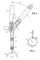
- Fig. 3 is a partial sectional view showing an exemplary embodiment of a measuring device according to the invention.
- Fig. 4 is a cross-sectional view explaining the principle of the invention applied to the measurement of the ovalization of a container.
- Fig. 5 is a view of an example of application of the measuring device according to the invention.
- the object of the invention aims to determine the thickness E of the wall 2 of a container 3 at least translucent and partially reflecting comprising an external face 2 1 , and a face internal 2 2 .
- the container 3 has a shape of revolution and corresponds to a bottle having an axis of vertical or longitudinal symmetry X.
- the method according to the invention consists in sending an incident light beam 1 from a source 1 1 , such as a laser, to a point A on the external face 2 1 , of the container 3 .
- the incident light beam 1 forms an angle of incidence a with respect to a transverse cross section T of the container or to a plane perpendicular to the vertical axis X and passing through the point A.
- the incident light beam 1 is substantially parallel to one of the generatrices G of the container, that is to say that it is situated in a diametral or vertical symmetry plane S passing through the vertical axis X. Under these conditions, the incident beam 1 , the generator G and the vertical axis X are contained in the diametral plane S or of vertical symmetry of the container 3 ( fig. 3 ).
- part 4 of the incident light beam 1 is reflected at point A , on the external face 2 1 of the container, while another part 5 is refracted inside the wall 2 .
- the refracted part 5 is reflected at a point B on the internal face 2 2 of the container and gives rise to the emission, at a point C of the external face 2 1 of the wall, of a refracted beam 6 .
- the reflected 4 and refracted 6 beams are emitted by the container 2 in two cross sections, respectively T, T 1 passing through the points A and C and located at different levels along the vertical axis X.
- the method according to the invention consists in determining the distance separating the reflected 4 and refracted 6 light rays by means of a measurement sensor 7 , such as a linear camera comprising a lens 8 , located upstream of a strip. photosensitive cells 9 .
- the bar 9 is placed in a given observation plane, so as to recover the reflected 4 and refracted 6 beams emitted by the container 2 according to two different cross-sections.
- the measuring strip 9 is placed so as to recover the refracted 6 and reflected 4 beams which are located in the plane of vertical symmetry S.
- the bar 9 is preferably located in a vertical plane coincident or parallel to the vertical plane of symmetry S of the bottle.
- the thickness E can be determined with relatively great precision, since the measurement of the thickness E of the wall in the vertical plane S overcomes the drawbacks associated with a thickness measurement in a horizontal plane. Indeed, this measurement in the vertical plane makes it possible to avoid the influence of the radius of curvature of the container, the ovalization of the container and the vertical movement of the container.
- the variation of the incident angle a is no longer linked to the ovalization and the change of position of the container, but depends solely on the surface condition of the container, as well as on the vertical variation of its profile.
- the method according to the invention makes it possible to determine the ovalization of the container 3 .
- the container 3 is rotated while remaining in permanent contact with a fulcrum 11 .
- the ovalization can thus be determined from the knowledge of the angle of incidence a and the distance D. It should be noted that the diameter of the container can be measured by the technique according to the invention.
- Figs. 3 and 5 illustrate an exemplary embodiment of a device 11 for measuring the thickness of the wall and / or the ovalization of a container 3 , implementing the method according to the invention described above.
- the measuring device 11 is designed to have a reduced bulk, insofar as it appears necessary to superimpose two or three devices, in order to control the thickness of the wall of the container at several levels ( fig. 5 ).
- the measuring device 11 comprises the light source 1 1 , such as a laser, the housing 1 2 of which is extended by an arm 12 , the end of which is provided with a deflection mirror 13 .
- the light beam 1 ' emitted by the source 1 1 is reflected by the mirror 13 , in order to form the incident beam 1 .
- the light beam 1 ′ emitted by the source 1 1 and the reflected 4 and refracted 6 beams are substantially parallel, so that the light source 1 1 and the measurement sensor 7 are inclined in the same direction, namely downwards in the exemplary embodiment illustrated. Therefore, the measurement sensor 7 can be associated or placed next to the light source 1 , in order to limit the size of the device 11 .
- the device 11 comprises a second deflection mirror 15 placed in the plane of symmetry S , so as to collect the reflected 4 and refracted 6 beams and to send them laterally towards the measurement sensor 7 .
- the aiming axis V of the measurement sensor 7 forms with the plane S an angle ⁇ of the order of 40 °, taken along a transverse cross section considered with respect to the container.
- the incident beam 1 is located in the vertical plane of symmetry S of the container. It should be noted that the incident beam 1 , while retaining its angle of incidence a , can be offset in the transverse plane T by a limited angle for example of ⁇ 15 °.
- the measuring bar 9 is placed in a plane parallel to the vertical plane S , according to the preferred embodiment described above. Of course, the measuring bar 9 can occupy a different position by implementing a particular optical system for returning the reflected 4 and refracted 6 beams.
Applications Claiming Priority (2)
| Application Number | Priority Date | Filing Date | Title |
|---|---|---|---|
| FR9704721A FR2762083B1 (fr) | 1997-04-11 | 1997-04-11 | Procede optique de mesure de l'epaisseur de la paroi et/ou de l'ovalisation d'un recipient et dispositif en faisant application |
| FR9704721 | 1997-04-11 |
Publications (1)
| Publication Number | Publication Date |
|---|---|
| EP0871007A1 true EP0871007A1 (de) | 1998-10-14 |
Family
ID=9506013
Family Applications (1)
| Application Number | Title | Priority Date | Filing Date |
|---|---|---|---|
| EP98420063A Withdrawn EP0871007A1 (de) | 1997-04-11 | 1998-04-10 | Optisches Wanddicken- und/oder Unrundheitmessverfahren und Vorrichtung zu seiner Verwendung |
Country Status (2)
| Country | Link |
|---|---|
| EP (1) | EP0871007A1 (de) |
| FR (1) | FR2762083B1 (de) |
Cited By (6)
| Publication number | Priority date | Publication date | Assignee | Title |
|---|---|---|---|---|
| US6549292B1 (en) | 2000-10-17 | 2003-04-15 | Agr International, Inc. | Method and apparatus for inspecting hollow transparent articles |
| DE102008018844A1 (de) * | 2008-04-15 | 2009-10-29 | VMA Gesellschaft für visuelle Meßtechnik und Automatisierung mbH | Vorrichtung und Verfahren zur berührungslosen Messung einer Wanddickeverteilung |
| WO2012110749A1 (fr) | 2011-02-18 | 2012-08-23 | Msc & Sgcc | Procede et dispositif pour detecter des defauts de repartition de matiere dans des recipients transparents |
| JP2015087302A (ja) * | 2013-10-31 | 2015-05-07 | 三菱日立パワーシステムズ株式会社 | 配管形状測定装置および配管形状測定方法 |
| WO2021110308A1 (de) * | 2019-12-02 | 2021-06-10 | Krones Aktiengesellschaft | Verfahren zum überprüfen einer wandstärke eines behälters aus einem zumindest teilweise transparenten material |
| EP2188108B2 (de) † | 2007-09-21 | 2023-02-22 | KHS GmbH | Verfahren zur blasformung von behältern |
Citations (6)
| Publication number | Priority date | Publication date | Assignee | Title |
|---|---|---|---|---|
| FR2069220A5 (de) * | 1969-11-11 | 1971-09-03 | British Aircraft Corp Ltd | |
| DE2325457A1 (de) * | 1972-05-22 | 1973-11-29 | Gabor Ujhelyi Kalman | Vorrichtung zum messen des abstandes von flaechen aus transparentem material |
| FR2481445A1 (fr) * | 1980-04-23 | 1981-10-30 | Thomson Csf | Procede et dispositif de mesure de caracteristiques geometriques d'un element en materiau refringent, notamment d'un tube |
| EP0248552A1 (de) * | 1986-05-14 | 1987-12-09 | Walter Roland Tole | Vorrichtung zur Bestimmung der Dicke von Material |
| US5291271A (en) | 1992-08-19 | 1994-03-01 | Owens-Brockway Glass Container Inc. | Measurement of transparent container wall thickness |
| WO1995022740A1 (fr) * | 1994-02-18 | 1995-08-24 | Saint Gobain Cinematique Et Controle | Procede de mesure d'epaisseur d'un materiau transparent |
-
1997
- 1997-04-11 FR FR9704721A patent/FR2762083B1/fr not_active Expired - Fee Related
-
1998
- 1998-04-10 EP EP98420063A patent/EP0871007A1/de not_active Withdrawn
Patent Citations (6)
| Publication number | Priority date | Publication date | Assignee | Title |
|---|---|---|---|---|
| FR2069220A5 (de) * | 1969-11-11 | 1971-09-03 | British Aircraft Corp Ltd | |
| DE2325457A1 (de) * | 1972-05-22 | 1973-11-29 | Gabor Ujhelyi Kalman | Vorrichtung zum messen des abstandes von flaechen aus transparentem material |
| FR2481445A1 (fr) * | 1980-04-23 | 1981-10-30 | Thomson Csf | Procede et dispositif de mesure de caracteristiques geometriques d'un element en materiau refringent, notamment d'un tube |
| EP0248552A1 (de) * | 1986-05-14 | 1987-12-09 | Walter Roland Tole | Vorrichtung zur Bestimmung der Dicke von Material |
| US5291271A (en) | 1992-08-19 | 1994-03-01 | Owens-Brockway Glass Container Inc. | Measurement of transparent container wall thickness |
| WO1995022740A1 (fr) * | 1994-02-18 | 1995-08-24 | Saint Gobain Cinematique Et Controle | Procede de mesure d'epaisseur d'un materiau transparent |
Non-Patent Citations (1)
| Title |
|---|
| EL-ZAIAT S Y: "MEASURING THE THICKNESS AND REFRACTIVE INDEX OF A THICK TRANSPARENT PLATE BY AN UNEXPANDED LASER BEAM", OPTICS AND LASER TECHNOLOGY, vol. 29, no. 2, March 1997 (1997-03-01), pages 63 - 65, XP000684438 * |
Cited By (11)
| Publication number | Priority date | Publication date | Assignee | Title |
|---|---|---|---|---|
| US6549292B1 (en) | 2000-10-17 | 2003-04-15 | Agr International, Inc. | Method and apparatus for inspecting hollow transparent articles |
| EP2188108B2 (de) † | 2007-09-21 | 2023-02-22 | KHS GmbH | Verfahren zur blasformung von behältern |
| DE102008018844A1 (de) * | 2008-04-15 | 2009-10-29 | VMA Gesellschaft für visuelle Meßtechnik und Automatisierung mbH | Vorrichtung und Verfahren zur berührungslosen Messung einer Wanddickeverteilung |
| WO2012110749A1 (fr) | 2011-02-18 | 2012-08-23 | Msc & Sgcc | Procede et dispositif pour detecter des defauts de repartition de matiere dans des recipients transparents |
| FR2971847A1 (fr) * | 2011-02-18 | 2012-08-24 | Tiama | Procede et dispositif pour detecter des defauts de repartition de matiere dans des recipients transparents |
| CN103477212A (zh) * | 2011-02-18 | 2013-12-25 | Msc&Sgcc公司 | 用于检测透明容器中材料分布缺陷的方法及装置 |
| JP2014506995A (ja) * | 2011-02-18 | 2014-03-20 | エムエスセ エ エスジェセセ | 透明な容器の材料に分布する欠陥を検出するための方法及び装置 |
| US9244020B2 (en) | 2011-02-18 | 2016-01-26 | Msc & Sgcc | Method and device for detecting defects in material distribution in transparent containers |
| CN103477212B (zh) * | 2011-02-18 | 2016-06-22 | Msc&Sgcc公司 | 用于检测透明容器中材料分布缺陷的方法及装置 |
| JP2015087302A (ja) * | 2013-10-31 | 2015-05-07 | 三菱日立パワーシステムズ株式会社 | 配管形状測定装置および配管形状測定方法 |
| WO2021110308A1 (de) * | 2019-12-02 | 2021-06-10 | Krones Aktiengesellschaft | Verfahren zum überprüfen einer wandstärke eines behälters aus einem zumindest teilweise transparenten material |
Also Published As
| Publication number | Publication date |
|---|---|
| FR2762083B1 (fr) | 1999-07-02 |
| FR2762083A1 (fr) | 1998-10-16 |
Similar Documents
| Publication | Publication Date | Title |
|---|---|---|
| EP0342123B1 (de) | Verfahren zur Positionierung eines Objektes in bezug auf eine Ebene, Längenmessverfahren und Vorrichtung zur Durchführung des Verfahrens | |
| EP1558920B1 (de) | Verfahren und vorrichtung zur detektion von oberflächenfehlern und/ oder fehlendem material eines ringförmigen gefässes mit hilfe einer beleuchtung | |
| EP1817574B1 (de) | Beleuchtungsverfahren und -vorrichtung zur bestimmung des vorliegens von defekten auf der oberfläche eines behälterbunds | |
| FR2491615A1 (fr) | Procede de mesure optoelectronique et dispositifs pour la determination de la qualite de surfaces a reflexion diffuse | |
| FR2716531A1 (fr) | Procédé de mesure d'épaisseur d'un matériau transparent. | |
| EP2297672B1 (de) | Verfahren und optische vorrichtung zur analyse einer markierung auf einer lichtdurchlässigen bzw. transparenten gekrümmten wand | |
| EP2909574B1 (de) | Einrichtung zur messung der wanddicke von behältern | |
| WO2006106271A2 (fr) | Procede et dispositif pour supprimer les reflets parasites lors de l'inspection a chaud d'objets creux translucides ou transparents | |
| EP0871007A1 (de) | Optisches Wanddicken- und/oder Unrundheitmessverfahren und Vorrichtung zu seiner Verwendung | |
| EP2691186B1 (de) | Verfahren und vorrichtung zur messung der vertikalität eines behälters | |
| FR2719900A1 (fr) | Procédé et dispositif pour la mesure in situ des contraintes se développant au sein d'une couche mince lors de son dépôt sur un substrat. | |
| FR2780533A1 (fr) | Procede et dispositif de lecture de reliefs portes par un recipient transparent ou translucide | |
| WO2004040277A1 (fr) | Procede et dispositif pour detecter des defauts de surface presentes par la paroi externe d'un objet transparent ou translucide | |
| EP1846727B1 (de) | Optische sonde und diese verwendende einrichtung und methode | |
| EP1407253A1 (de) | Methode und vorrichtung zur prüfung der oberfläche einer walzwerkwalze | |
| EP2742320B1 (de) | Optoelektronisches verfahren und vorrichtung zur messung des innendurchmessers eines hohlkörpers | |
| CH369903A (fr) | Procédé pour la détermination d'une propriété optique d'une couche superficielle d'un milieu transparent et appareil pour la mise en oeuvre de ce procédé | |
| FR2629909A1 (fr) | Methode et appareil pour mesurer les micro-distances | |
| FR2556467A1 (fr) | Dispositif d'eclairement d'un liquide contenu dans un recipient, en vue de son controle | |
| FR2670883A1 (fr) | Dispositif de detection des irregularites du diametre d'un fil. | |
| FR2469697A1 (fr) | Appareil de mesure optique de la distance entre deux points d'un objet | |
| FR3020137A1 (fr) | Dispositif de controle dimensionnel de recipients par detection optique sans contact | |
| EP0101375A1 (de) | Verfahren und Anordnung zur kontaktlosen Bestimmung der Rauheit einer Obefläche | |
| EP0484310B1 (de) | Vorrichtung zum Messen der Rauhigkeit eines sich bewegenden Metallerzeugnisses | |
| FR2798995A1 (fr) | Installation pour determiner les caracteristiques de transmission lumineuse du materiau constitutif d'un recipient |
Legal Events
| Date | Code | Title | Description |
|---|---|---|---|
| PUAI | Public reference made under article 153(3) epc to a published international application that has entered the european phase |
Free format text: ORIGINAL CODE: 0009012 |
|
| AK | Designated contracting states |
Kind code of ref document: A1 Designated state(s): AT BE CH DE DK ES GB IE IT LI NL |
|
| AX | Request for extension of the european patent |
Free format text: AL;LT;LV;MK;RO;SI |
|
| RTI1 | Title (correction) | ||
| 17P | Request for examination filed |
Effective date: 19990412 |
|
| AKX | Designation fees paid |
Free format text: AT BE CH DE DK ES GB IE IT LI NL |
|
| TPAD | Observations filed by third parties |
Free format text: ORIGINAL CODE: EPIDOS TIPA |
|
| 17Q | First examination report despatched |
Effective date: 20031021 |
|
| RAP1 | Party data changed (applicant data changed or rights of an application transferred) |
Owner name: TIAMA |
|
| STAA | Information on the status of an ep patent application or granted ep patent |
Free format text: STATUS: THE APPLICATION IS DEEMED TO BE WITHDRAWN |
|
| 18D | Application deemed to be withdrawn |
Effective date: 20040501 |