EP0870854B1 - Method and apparatus for cleaning metal strips - Google Patents
Method and apparatus for cleaning metal strips Download PDFInfo
- Publication number
- EP0870854B1 EP0870854B1 EP98302382A EP98302382A EP0870854B1 EP 0870854 B1 EP0870854 B1 EP 0870854B1 EP 98302382 A EP98302382 A EP 98302382A EP 98302382 A EP98302382 A EP 98302382A EP 0870854 B1 EP0870854 B1 EP 0870854B1
- Authority
- EP
- European Patent Office
- Prior art keywords
- strip
- cleaning
- nozzles
- electrolytically
- opposed
- Prior art date
- Legal status (The legal status is an assumption and is not a legal conclusion. Google has not performed a legal analysis and makes no representation as to the accuracy of the status listed.)
- Expired - Lifetime
Links
Images


Classifications
-
- C—CHEMISTRY; METALLURGY
- C25—ELECTROLYTIC OR ELECTROPHORETIC PROCESSES; APPARATUS THEREFOR
- C25F—PROCESSES FOR THE ELECTROLYTIC REMOVAL OF MATERIALS FROM OBJECTS; APPARATUS THEREFOR
- C25F7/00—Constructional parts, or assemblies thereof, of cells for electrolytic removal of material from objects; Servicing or operating
-
- C—CHEMISTRY; METALLURGY
- C25—ELECTROLYTIC OR ELECTROPHORETIC PROCESSES; APPARATUS THEREFOR
- C25F—PROCESSES FOR THE ELECTROLYTIC REMOVAL OF MATERIALS FROM OBJECTS; APPARATUS THEREFOR
- C25F1/00—Electrolytic cleaning, degreasing, pickling or descaling
Definitions
- the present invention relates to a method and an apparatus for cleaning a metal strip, and more particularly, to a method and an apparatus for cleaning a metal strip by an electrolytically cleaning technique in the steel industry.
- the positive and negative plates should be relatively widely spaced away from the strip passing through the alkali solution, or namely the plates should be arranged with a sufficient space.
- a large current should be applied to the plates so as to electrolytically clean the strip. Conventionally a current at about 4,000 to about 10,000 amps. has been applied to the plates. If a large current is applied, a serious problem of electric corrosion is raised due to stray current.
- the plates are disposed with a space of about 1.5 m at 10 to 30 locations in the travelling direction of the strip in a strip-cleaning line which is operated at a running speed of about 500 to about 700 m/min.
- an alkali aqueous solution flows out from an electrolytic cell and can be returned after regeneration or after replenishment with a new alkali aqueous solution outside the electrolytic cell. Even in this case, a large amount of alkali aqueous solution (about 20 to about 30 m 3 ) should be held in the electrolytic cell. This denotes that only a low energy effect is produced in the electrolytically cleaning operation, and that a large-scale electrolytically cleaning equipment is required which incurs a high running cost and a high maintenance cost.
- the conventional electrolytically cleaning system is of immersion type, the oil deposited on the strip is released into the alkaline bath and unavoidably re-deposits on the strip passing through the alkaline bath, resulting in reduced degreasing or cleaning efficiency in addition to the foregoing deficiency.
- An object of the present invention is to overcome the foregoing prior art problems. Stated more specifically, the object of the invention is to provide a method and an apparatus for cleaning a metal strip by an electrolytically cleaning technique with the following advantages:
- a method for cleaning a metal strip comprising the steps of:
- an apparatus for cleaning a metal strip comprising at least one cleaning unit comprising:
- one of the opposed nozzles for ejecting an alkali aqueous solution over the strip is the anode and the other is the cathode.
- the strip to be treated is passed between the opposed nozzles, whereby it is electrolytically cleaned.
- the solution is forced out from the nozzles at a pressure which is inversely proportional to the distance between the nozzle and the strip. Consequently, the strip coming closer to the nozzles is exposed to a higher pressure according to the distance between the nozzle and the strip. The nearer the strip moves, the more strongly it is prevented from moving closer by a higher pressure.
- the strip when the alkali aqueous solution is supplied, at a pressure of 1 kg/cm 2 , to the nozzles spaced by 10 mm from the strip, the strip can pass between the nozzles without contact nor collision with the nozzles serving as the electrodes.
- the opposed electrodes can be arranged with such a short space that a high electrolytically cleaning efficiency can be achieved by application of a small current which overcomes the prior art problem of electric corrosion owing to stray current by application of a large current.
- the current density per input unit of power can be much more increased than in the prior art, whereby a strip can be electrolytically cleaned with a noticeably high efficiency.
- the desired electrolytically cleaning effect can be produced using nozzles, 7 to 8 mm in size in the strip-travelling direction, in the strip-cleaning line which is operated at the above-mentioned running speed.
- nozzles 7 to 8 mm in size in the strip-travelling direction, in the strip-cleaning line which is operated at the above-mentioned running speed.
- a large amount of electrolyte need not be held in the electrolytic cell so that a high energy effect can be achieved by the electrolytically cleaning operation.
- the electrolytically cleaning effect can be achieved as contemplated by application of power of 10 amps at 7-8 volts using a single cleaning unit with nozzles of the above-mentioned size arranged at a distance of 10 mm between the nozzle and the strip in a strip-cleaning line which is operated at the above running speed.
- the conventional techniques require power of 4000 to 10000 amps at 20 volts in a strip-cleaning line which is operated at the same running speed.
- a significantly smaller size electrolytically cleaning equipment can be provided, and the electrolytically cleaning equipment can be operated at a far lower running cost and can be maintained at a lower cost, than in the prior art.
- the oil deposited on the strip can be removed from the strip in a short time by the above-mentioned electrolytically cleaning operation.
- the oil loosely existing to the strip surface can be easily washed away by the alkali aqueous solution ejected from the nozzles.
- the strip is exposed to a spray of cleaning water and simultaneously brushed with a brush roll or brush rolls arranged next to the electrolytically cleaning means downstream thereof in the travelling direction of the strip.
- a brush roll or brush rolls arranged next to the electrolytically cleaning means downstream thereof in the travelling direction of the strip.
- the oil particles existing in the electrolyte can not be re-deposited on the strip in the invention unlike the conventional immersion-type electrolytically cleaning system, so that a high electrolytically cleaning efficiency can be achieved in the invention in this respect, and the energy effect can be enhanced by the electrolytically cleaning operation.
- Iron particles can also be eliminated from the strip in the brush cleaning step.
- the strip cleaned by the preceding cleaning operation is further cleaned by the subsequent cleaning operation, whereby a better cleaning result is given.
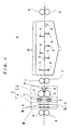
- Fig. 1 is a front view schematically showing an embodiment of the system for cleaning a strip according to the present invention.
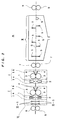
- Fig. 2 is a front view schematically showing another embodiment of the system for cleaning a strip according to the present invention.
- Fig. 3 is a perspective view of the nozzles in the systems for cleaning a strip as shown in Figs. 1 and 2.
- Fig. 4 is a section view schematically showing an nozzle to be arranged in the systems for cleaning a strip as shown in Figs. 1 and 2.
- the apparatus A comprises a cleaning unit I.
- the cleaning unit I includes a first section Ia and a second section Ib.
- the first section Ia includes nozzles 1, 2 arranged as vertically opposed.
- One of the nozzles 1, 2 is a positive electrode and the other is a negative electrode from each of which an alkali aqueous solution is ejected.
- the first section Ia is one wherein the electrolytically cleaning step for a strip S to be cleaned is carried out.
- the second section Ib includes a brushing roll(s) 3 for brushing the strip S in a spray of cleaning water.
- the second section Ib is one wherein the brush cleaning step for the strip S is carried out.
- the brushing roll(s) 3 in the second section Ib is disposed next to the nozzles 1, 2 in the first section Ia downstream thereof in the travelling direction of the strip S.
- the nozzles 1, 2 are connected to lines la, 2a for supply of alkali aqueous solution.
- the alkali aqueous solution ejected from the nozzles 1, 2 is passed through a circulating line (not shown) and is returned to the lines 1a, 2a for reuse.
- the cleaning unit I including the first and second sections Ia, Ib may be disposed singly as shown in Fig. 1 or may be arranged in a plurality in the travelling direction of the strip S as shown in Fig. 2.
- the brush roll(s) 3 in the second section Ib can be any of conventional brush rolls.
- the cleaning water is sprayed by the per se known method concurrently with brushing with a brush roll(s) 3. Accordingly the mode of spraying the cleaning water and the mode of bushing with a brush roll or brush rolls are only diagrammatically represented in the drawings.
- Designated 4 is a nozzle for spraying the cleaning water as an example of means for spraying the cleaning water.
- the apparatus A has a rinsing-type cleaning unit II disposed next to the cleaning unit I downstream thereof in the travelling direction of the strip S.
- the cleaning unit II may be conventional.
- a spray header for the cleaning water is designated 5 and a back-up roller for the strip S is designated 6.
- a wringer roller 7 is disposed between the cleaning unit I and the cleaning unit II set next thereto, a wringer roller 8 is disposed on the side of entry into the first section Ia and a wringer roller 9 is disposed on the side of exit from the cleaning unit II.
- a voltage is applied to the nozzles 1, 2 one of which is the anode and the other of which is the cathode.
- An alkali aqueous solution is forced out from the nozzles 1, 2.
- the strip S to be cleaned is passed between the opposed nozzles 1, 2 while being exposed to a jet of the alkali aqueous solution forced out from the nozzles 1, 2, whereby the strip S is electrolytically cleaned.
- a voltage to the nozzles 1, 2 when the running speed of the strip S travelling in the strip-cleaning line has reached 10 m/min or more instead of applying a voltage immediately after the beginning of travelling. If a voltage is applied immediately after the beginning of running, damage such as change of property may be inflicted on the strip. The damage is caused presumably because a current applied to the nozzles 1, 2 flows into the strip and heats the strip. The problem of causing such damage is obviated if a voltage is applied to the nozzles 1, 2 when the running speed of the strip S travelling in the strip-cleaning line has reached 10 m/min or more.
- the nozzle positioned above is the cathode and the one positioned below is the anode. If the arrangement of nozzles 1, 2 is reverse to the foregoing exemplar, the strip to be cleaned may be insufficiently cleaned on side portions. This problem would be overcome if the upper nozzle is the cathode and the lower nozzle is the anode.
- the nozzles 1, 2 are vertically opposed, and preferably diametrically opposed. If the nozzles 1, 2 are provided in diametrically opposite arrangement, the strip can be cleaned at the best electrolysis intensity.
- the strip S to be cleaned is wetted with cleaning water at a location adjacent to the side of entry into the cleaning unit I and is passed through the first section Ia.
- the strip S is electrolytically cleaned with an enhanced effect.
- a zone III is one wherein the strip S is wetted with cleaning water at a location adjacent to the side of entry into the cleaning unit I, and a spray III-5 is disposed in the zone III.
- the strip S which has passed through the first section Ia is cleaned by being brushed, in a spray of cleaning water, with a brush roll or brush rolls 3 at a position(s) adjacent to the nozzles 1, 2 downstream thereof in the travelling direction of the strip S.
- the strip S treated at the second section Ib in the terminal end of the cleaning unit I is rinsed with water in the cleaning unit II.
- the oil remaining on the strip S cleaned in the cleaning unit I is removed by cleaning in the cleaning unit II.
- the remaining oil so loosely exist to the strip that the oil can be efficiently washed away in the cleaning unit II.
Landscapes
- Chemical & Material Sciences (AREA)
- Engineering & Computer Science (AREA)
- Chemical Kinetics & Catalysis (AREA)
- Electrochemistry (AREA)
- Materials Engineering (AREA)
- Metallurgy (AREA)
- Organic Chemistry (AREA)
- Cleaning And De-Greasing Of Metallic Materials By Chemical Methods (AREA)
- Electrolytic Production Of Metals (AREA)
Description
- The present invention relates to a method and an apparatus for cleaning a metal strip, and more particularly, to a method and an apparatus for cleaning a metal strip by an electrolytically cleaning technique in the steel industry.
- Methods for electrolytically cleaning a strip have been conventionally carried out in the steel industry by passing a metal strip between opposed positive and negative plates in an aqueous solution of alkali held in an electrolytic cell. These conventional methods, however, entail the following problems.
- Usually a strip passing between the positive and negative plates moves zigzag in the direction of strip thickness. Consequently, the strip may contact or collide with the positive or negative plates due to the zigzag movement. To avoid the contact or collision, the positive and negative plates should be relatively widely spaced away from the strip passing through the alkali solution, or namely the plates should be arranged with a sufficient space. In the arrangement of plates widely spaced away, a large current should be applied to the plates so as to electrolytically clean the strip. Conventionally a current at about 4,000 to about 10,000 amps. has been applied to the plates. If a large current is applied, a serious problem of electric corrosion is raised due to stray current.
- If a small current is applied to the plates to overcome the problem of electric corrosion resulting from stray current by application of a large current, a low current density results, leading to a reduced electrolytically cleaning effect.
- According to the conventional techniques for electrolytically cleaning a strip, the plates are disposed with a space of about 1.5 m at 10 to 30 locations in the travelling direction of the strip in a strip-cleaning line which is operated at a running speed of about 500 to about 700 m/min.
- In this mode of electrolytically cleaning operation, an alkali aqueous solution flows out from an electrolytic cell and can be returned after regeneration or after replenishment with a new alkali aqueous solution outside the electrolytic cell. Even in this case, a large amount of alkali aqueous solution (about 20 to about 30 m3) should be held in the electrolytic cell. This denotes that only a low energy effect is produced in the electrolytically cleaning operation, and that a large-scale electrolytically cleaning equipment is required which incurs a high running cost and a high maintenance cost.
- Since the conventional electrolytically cleaning system is of immersion type, the oil deposited on the strip is released into the alkaline bath and unavoidably re-deposits on the strip passing through the alkaline bath, resulting in reduced degreasing or cleaning efficiency in addition to the foregoing deficiency.
- An object of the present invention is to overcome the foregoing prior art problems. Stated more specifically, the object of the invention is to provide a method and an apparatus for cleaning a metal strip by an electrolytically cleaning technique with the following advantages:
- (1) a high electrolytically cleaning efficiency can be achieved by application of a small current;
- (2) it is possible to resolve the problem posed by the conventional techniques due to stray current by application of a large current,
- (3) a high energy effect can be produced by the electrolytically cleaning operation,
- (4) a significantly small-size electrolytically cleaning equipment compared with conventional one can be provided,
- (5) the running cost in the electrolytically cleaning operation can be decreased far below the costs heretofore involved,
- (6) the maintenance cost in the electrolytically cleaning operation can be lowered, and
- (7) the oil released from the strip by the electrolytically cleaning operation is prevented from redepositing on the strip.
-
- According to the present invention, there is provided a method for cleaning a metal strip, the method comprising the steps of:
- (i) electrolytically cleaning a strip to be cleaned by passing the strip between opposed nozzles for ejecting an alkali aqueous solution over the strip, one of the nozzles being a positive electrode and the other being a negative electrode, and a voltage being applied to the nozzles, and
- (ii) brushing, in a spray of cleaning water, the strip with a brush roll or brush rolls disposed at a position(s) adjacent to the nozzles of the electrolytically cleaning step (i) downstream of the nozzles in the travelling direction of the strip, the strip being subjected at least once to the procedures in the steps (i) and (ii).
-
- According to the present invention, there is also provided an apparatus for cleaning a metal strip, the apparatus comprising at least one cleaning unit comprising:
- (a) opposed nozzles for ejecting an alkali aqueous solution over the strip between which the strip to be cleaned is passed, one of the nozzles being a positive electrode and the other being a negative electrode, and
- (b) a brush roll or brush rolls for brushing the strip in a spray of cleaning water, the brush roll or rolls being disposed at a position(s) adjacent to the nozzles downstream thereof in the travelling direction of the strip.
-
- According to the present invention, one of the opposed nozzles for ejecting an alkali aqueous solution over the strip is the anode and the other is the cathode. The strip to be treated is passed between the opposed nozzles, whereby it is electrolytically cleaned.
- In this case, when moving zigzag even in a narrow space between the nozzles, the strip neither contacts nor collides with the nozzles for the following reasons.
- The solution is forced out from the nozzles at a pressure which is inversely proportional to the distance between the nozzle and the strip. Consequently, the strip coming closer to the nozzles is exposed to a higher pressure according to the distance between the nozzle and the strip. The nearer the strip moves, the more strongly it is prevented from moving closer by a higher pressure.
- According to the invention, when the alkali aqueous solution is supplied, at a pressure of 1 kg/cm2, to the nozzles spaced by 10 mm from the strip, the strip can pass between the nozzles without contact nor collision with the nozzles serving as the electrodes.
- In accordance with the present invention, the opposed electrodes can be arranged with such a short space that a high electrolytically cleaning efficiency can be achieved by application of a small current which overcomes the prior art problem of electric corrosion owing to stray current by application of a large current.
- According to the present invention, the current density per input unit of power can be much more increased than in the prior art, whereby a strip can be electrolytically cleaned with a noticeably high efficiency.
- For example, the desired electrolytically cleaning effect can be produced using nozzles, 7 to 8 mm in size in the strip-travelling direction, in the strip-cleaning line which is operated at the above-mentioned running speed. In this embodiment, a large amount of electrolyte need not be held in the electrolytic cell so that a high energy effect can be achieved by the electrolytically cleaning operation.
- Stated more specifically, the electrolytically cleaning effect can be achieved as contemplated by application of power of 10 amps at 7-8 volts using a single cleaning unit with nozzles of the above-mentioned size arranged at a distance of 10 mm between the nozzle and the strip in a strip-cleaning line which is operated at the above running speed. In contrast, the conventional techniques require power of 4000 to 10000 amps at 20 volts in a strip-cleaning line which is operated at the same running speed.
- According to the invention, a significantly smaller size electrolytically cleaning equipment can be provided, and the electrolytically cleaning equipment can be operated at a far lower running cost and can be maintained at a lower cost, than in the prior art.
- The oil deposited on the strip can be removed from the strip in a short time by the above-mentioned electrolytically cleaning operation. The oil loosely existing to the strip surface can be easily washed away by the alkali aqueous solution ejected from the nozzles.
- In the brush cleaning step, the strip is exposed to a spray of cleaning water and simultaneously brushed with a brush roll or brush rolls arranged next to the electrolytically cleaning means downstream thereof in the travelling direction of the strip. As a result, the oil remaining on the strip can be effectively removed by the brush roll or brush rolls in the brush cleaning step.
- Therefore, the oil particles existing in the electrolyte can not be re-deposited on the strip in the invention unlike the conventional immersion-type electrolytically cleaning system, so that a high electrolytically cleaning efficiency can be achieved in the invention in this respect, and the energy effect can be enhanced by the electrolytically cleaning operation. Iron particles can also be eliminated from the strip in the brush cleaning step.
- In the practice of the invention, when the strip is subjected a plurality of times to the electrolytically cleaning step and the brushing cleaning step to be executed in the strip-travelling direction, the strip cleaned by the preceding cleaning operation is further cleaned by the subsequent cleaning operation, whereby a better cleaning result is given.
- Fig. 1 is a front view schematically showing an embodiment of the system for cleaning a strip according to the present invention.
- Fig. 2 is a front view schematically showing another embodiment of the system for cleaning a strip according to the present invention.
- Fig. 3 is a perspective view of the nozzles in the systems for cleaning a strip as shown in Figs. 1 and 2.
- Fig. 4 is a section view schematically showing an nozzle to be arranged in the systems for cleaning a strip as shown in Figs. 1 and 2.
- Preferred embodiments of the invention are described below with reference to the accompanying drawings.
- Indicated at a reference character A is an apparatus for cleaning a strip as a whole. The apparatus A comprises a cleaning unit I. The cleaning unit I includes a first section Ia and a second section Ib.
- The first section Ia includes
nozzles nozzles - The second section Ib includes a brushing roll(s) 3 for brushing the strip S in a spray of cleaning water. The second section Ib is one wherein the brush cleaning step for the strip S is carried out. The brushing roll(s) 3 in the second section Ib is disposed next to the
nozzles - The
nozzles nozzles - The cleaning unit I including the first and second sections Ia, Ib may be disposed singly as shown in Fig. 1 or may be arranged in a plurality in the travelling direction of the strip S as shown in Fig. 2.
- The brush roll(s) 3 in the second section Ib can be any of conventional brush rolls. The cleaning water is sprayed by the per se known method concurrently with brushing with a brush roll(s) 3. Accordingly the mode of spraying the cleaning water and the mode of bushing with a brush roll or brush rolls are only diagrammatically represented in the drawings. Designated 4 is a nozzle for spraying the cleaning water as an example of means for spraying the cleaning water.
- In the illustrated embodiments, the apparatus A has a rinsing-type cleaning unit II disposed next to the cleaning unit I downstream thereof in the travelling direction of the strip S. The cleaning unit II may be conventional. A spray header for the cleaning water is designated 5 and a back-up roller for the strip S is designated 6.
- A
wringer roller 7 is disposed between the cleaning unit I and the cleaning unit II set next thereto, awringer roller 8 is disposed on the side of entry into the first section Ia and awringer roller 9 is disposed on the side of exit from the cleaning unit II. - A voltage is applied to the
nozzles nozzles - The strip S to be cleaned is passed between the
opposed nozzles nozzles - In the electrolytically cleaning operation, it is preferred to apply a voltage to the
nozzles nozzles nozzles - Of the
nozzles nozzles - The
nozzles nozzles - The strip S to be cleaned is wetted with cleaning water at a location adjacent to the side of entry into the cleaning unit I and is passed through the first section Ia. In this case, the strip S is electrolytically cleaned with an enhanced effect.
- In Figs. 1 and 2, a zone III is one wherein the strip S is wetted with cleaning water at a location adjacent to the side of entry into the cleaning unit I, and a spray III-5 is disposed in the zone III.
- The strip S which has passed through the first section Ia is cleaned by being brushed, in a spray of cleaning water, with a brush roll or brush rolls 3 at a position(s) adjacent to the
nozzles - In the illustrated embodiments, the strip S treated at the second section Ib in the terminal end of the cleaning unit I is rinsed with water in the cleaning unit II.
- The oil remaining on the strip S cleaned in the cleaning unit I is removed by cleaning in the cleaning unit II. In this case, the remaining oil so loosely exist to the strip that the oil can be efficiently washed away in the cleaning unit II.
Claims (9)
- A method for cleaning a metal strip, the method comprising the steps of:(i) electrolytically cleaning a metal strip to be cleaned by passing the strip between opposed nozzles (1,2) for ejecting an alkali aqueous solution over the strip, one of the nozzles (1) being a positive electrode and the other (2) being a negative electrode, and a voltage being applied to the nozzles, and(ii) brushing, in a spray of cleaning water, the strip with a brush roll or brush rolls (3) disposed at a position(s) adjacent to the nozzles of the electrolytically cleaning step (i) downstream of the nozzles in the travelling direction of the strip, the strip being subjected at least once to the procedures in the steps (i) and (ii).
- The method according to claim 1, wherein the strip is subjected at least twice to the procedures in the steps (i) and (ii).
- The method according to claim 1 which includes a step of wetting the strip with cleaning water to be conducted before the cleaning step (i) is carried out.
- The method according to claim 1, wherein the nozzles (1,2) are vertically opposed, and the nozzle (1) positioned above is the cathode and the one positioned below is the anode.
- The method according to claim 1, wherein a voltage is applied to the nozzles (1,2) when the running speed of the strip travelling in the strip-cleaning line has reached 10 m/min or more instead of applying a voltage immediately after the beginning of travelling.
- An apparatus for cleaning a metal strip, the apparatus comprising at least one cleaning unit comprising:(a) opposed nozzles (1,2) for ejecting an alkali aqueous solution over the strip between which the strip to be cleaned is passed, one of the nozzles (1) being a positive electrode and the other being a negative electrode (2), and(b) a brush roll or brush rolls (3) for brushing the strip in a spray of cleaning water, the brush roll or brush rolls being disposed at a position(s) adjacent to the nozzles downstream thereof in the travelling direction of the strip.
- The apparatus according to claim 6, wherein a plurality of the cleaning unit are provided in the travelling direction of the strip.
- The apparatus according to claim 6, wherein a spray for spraying the strip with cleaning water is provided at a location adjacent to the nozzles upstream thereof in the travelling direction of the strip.
- The apparatus according to claim 6, wherein the opposed nozzles are arranged in upper and lower positions and wherein the nozzle positioned above is the cathode and the one positioned below is the anode.
Applications Claiming Priority (3)
| Application Number | Priority Date | Filing Date | Title |
|---|---|---|---|
| JP09226097A JP3780392B2 (en) | 1996-12-18 | 1997-04-10 | Strip cleaning method and cleaning apparatus |
| JP9226097 | 1997-04-10 | ||
| JP92260/97 | 1997-04-10 |
Publications (2)
| Publication Number | Publication Date |
|---|---|
| EP0870854A1 EP0870854A1 (en) | 1998-10-14 |
| EP0870854B1 true EP0870854B1 (en) | 2002-01-16 |
Family
ID=14049448
Family Applications (1)
| Application Number | Title | Priority Date | Filing Date |
|---|---|---|---|
| EP98302382A Expired - Lifetime EP0870854B1 (en) | 1997-04-10 | 1998-03-27 | Method and apparatus for cleaning metal strips |
Country Status (5)
| Country | Link |
|---|---|
| US (1) | US6216304B1 (en) |
| EP (1) | EP0870854B1 (en) |
| KR (1) | KR100490573B1 (en) |
| DE (1) | DE69803138T2 (en) |
| ES (1) | ES2172084T3 (en) |
Cited By (1)
| Publication number | Priority date | Publication date | Assignee | Title |
|---|---|---|---|---|
| EP3514263A2 (en) | 2018-01-23 | 2019-07-24 | SMS Group GmbH | Method and device for electrolytic coating a metal strip |
Families Citing this family (9)
| Publication number | Priority date | Publication date | Assignee | Title |
|---|---|---|---|---|
| JP2000064100A (en) | 1998-08-24 | 2000-02-29 | Hitachi Ltd | Descaling apparatus for steel strip and apparatus for producing steel strip |
| JP3808239B2 (en) * | 1999-06-09 | 2006-08-09 | Jfeスチール株式会社 | Steel strip degreasing method |
| US6270620B1 (en) * | 1999-09-14 | 2001-08-07 | World Wiser Electronics Inc. | Etching device |
| US6960282B2 (en) * | 2001-12-21 | 2005-11-01 | International Business Machines Corporation | Apparatus for cleaning residual material from an article |
| ITMI20130497A1 (en) | 2013-03-29 | 2014-09-30 | Tenova Spa | EQUIPMENT FOR THE CONTINUOUS SURFACE ELECTROLYTIC TREATMENT OF METALLIC SEMI-FINISHED PRODUCTS, IN PARTICULAR FLAT METALLIC SEMI-FINISHED PRODUCTS. |
| KR101709128B1 (en) | 2015-11-26 | 2017-02-22 | 주식회사 포스코 | Rotation window for equipment inner sight |
| CN105951163A (en) * | 2016-07-07 | 2016-09-21 | 侯马市隆成电光源材料有限公司 | Continuous electrolytic polishing equipment |
| DE102018215809A1 (en) | 2018-01-23 | 2019-07-25 | Sms Group Gmbh | Apparatus and method for the electrolytic treatment of a metal strip |
| KR20220073555A (en) | 2020-11-26 | 2022-06-03 | (주)이녹스첨단소재 | Apparatus for cleaning metal sheet used for organic electronic device incapsulant and system for manufacturing organic electronic device incapsulant compring the same |
Family Cites Families (11)
| Publication number | Priority date | Publication date | Assignee | Title |
|---|---|---|---|---|
| US2278944A (en) * | 1939-04-28 | 1942-04-07 | Carnegie Illinois Steel Corp | Brushing apparatus for metallic strip |
| US2372599A (en) * | 1940-03-29 | 1945-03-27 | John S Nachtman | Electrolytic cleaning and pickling of metal surfaces |
| US2321179A (en) * | 1941-02-25 | 1943-06-08 | Blaw Knox Co | Sheet-cleaning apparatus |
| AU540287B2 (en) * | 1982-02-10 | 1984-11-08 | Nippon Steel Corporation | Continuous electrolytic treatment of metal strip using horizontal electrodes |
| JPS6056439B2 (en) | 1982-06-16 | 1985-12-10 | 日本鋼管株式会社 | Method for preventing foaming of electrolytic cleaning solution |
| DE3606750A1 (en) * | 1986-03-01 | 1987-09-03 | Hoesch Stahl Ag | METHOD, SYSTEM AND DEVICE FOR CONTINUOUSLY DEGREASING AND CLEANING THE SURFACE OF METAL BANDS, ESPECIALLY COLD ROLLED TAPE STEEL |
| JPH0356699A (en) * | 1989-07-24 | 1991-03-12 | Sumitomo Heavy Ind Ltd | Method and device for descaling strip |
| DE4121032A1 (en) * | 1991-06-26 | 1993-01-07 | Schmid Gmbh & Co Geb | DEVICE FOR TREATING PLATE-SHAPED OBJECTS, IN PARTICULAR BOARDS |
| FR2697539B1 (en) | 1992-11-03 | 1994-12-02 | Pechiney Recherche | Method, device and apparatus for surface treatment of bodies of metal cans, in particular an al or its alloys. |
| JPH08258090A (en) | 1995-03-23 | 1996-10-08 | Tokuo Okabayashi | Method and apparatus for washing stamper |
| US8450649B2 (en) * | 2008-11-07 | 2013-05-28 | Lincoln Global, Inc. | Addition of lithium aluminate to improve the performance of self shielded electrodes |
-
1998
- 1998-03-27 DE DE69803138T patent/DE69803138T2/en not_active Expired - Lifetime
- 1998-03-27 EP EP98302382A patent/EP0870854B1/en not_active Expired - Lifetime
- 1998-03-27 ES ES98302382T patent/ES2172084T3/en not_active Expired - Lifetime
- 1998-04-06 US US09/055,598 patent/US6216304B1/en not_active Expired - Lifetime
- 1998-04-10 KR KR10-1998-0012913A patent/KR100490573B1/en not_active IP Right Cessation
Cited By (1)
| Publication number | Priority date | Publication date | Assignee | Title |
|---|---|---|---|---|
| EP3514263A2 (en) | 2018-01-23 | 2019-07-24 | SMS Group GmbH | Method and device for electrolytic coating a metal strip |
Also Published As
| Publication number | Publication date |
|---|---|
| EP0870854A1 (en) | 1998-10-14 |
| DE69803138D1 (en) | 2002-02-21 |
| DE69803138T2 (en) | 2002-11-14 |
| ES2172084T3 (en) | 2002-09-16 |
| KR19980081313A (en) | 1998-11-25 |
| KR100490573B1 (en) | 2005-11-21 |
| US6216304B1 (en) | 2001-04-17 |
Similar Documents
| Publication | Publication Date | Title |
|---|---|---|
| EP0870854B1 (en) | Method and apparatus for cleaning metal strips | |
| US6071400A (en) | Method and device for the electrochemical treatment with treatment liquid of an item to be treated | |
| CN105499192A (en) | Copper foil slitting and cleaning device and copper foil slitting and cleaning method | |
| JP2001501674A (en) | Electrolytic cleaning method for conductive surface | |
| JP5146841B2 (en) | Plating equipment | |
| JP3808239B2 (en) | Steel strip degreasing method | |
| US6972082B2 (en) | Method for the selectively electroplating a strip-shaped, metal support material | |
| JP3813998B2 (en) | Surface electrolytic treatment method and apparatus | |
| JP3780392B2 (en) | Strip cleaning method and cleaning apparatus | |
| US6387227B1 (en) | Metal plate electrolyzation apparatus and electrode for electrolyzing metal plate | |
| JP2000064100A (en) | Descaling apparatus for steel strip and apparatus for producing steel strip | |
| EP1356138B1 (en) | Process and apparatus for the superficial electrolytic treatment of metal strips | |
| JP3168928B2 (en) | Steel plate cleaning equipment | |
| JPH083797A (en) | Cleaning device for steel sheet and method for preventing discoloration using the same | |
| JPH1170414A (en) | Work rustproofing method and device for wire discharge machine | |
| JPS6011097Y2 (en) | Electroplating device for moving metal strips | |
| KR0149754B1 (en) | Method for preventing arc-spot in radial type electroplating process | |
| CN116555871A (en) | Roll-to-roll electroplating film horizontal surface electroplating treatment tank and electroplating treatment device | |
| JPH05295576A (en) | Method for continuously degreasing metallic wire | |
| JP3219188B2 (en) | Method for cleaning a conductive rod and equipment for cleaning the conductive rod for implementing the method | |
| JPH09234507A (en) | Method for washing cold-rolled steel strip | |
| JPH08176899A (en) | Method for electrolytically cleaning steel strip | |
| JPH0759760B2 (en) | Ultra-thin metal strip cleaning equipment | |
| JPH1046377A (en) | Continuous degreasing method for metallic band and equipment therefor | |
| JP2001200398A (en) | Method for electrolytic cleaning of metallic strip |
Legal Events
| Date | Code | Title | Description |
|---|---|---|---|
| PUAI | Public reference made under article 153(3) epc to a published international application that has entered the european phase |
Free format text: ORIGINAL CODE: 0009012 |
|
| AK | Designated contracting states |
Kind code of ref document: A1 Designated state(s): DE ES FR GB IT |
|
| AX | Request for extension of the european patent |
Free format text: AL;LT;LV;MK;RO;SI |
|
| 17P | Request for examination filed |
Effective date: 19990401 |
|
| AKX | Designation fees paid |
Free format text: DE ES FR GB IT |
|
| 17Q | First examination report despatched |
Effective date: 20000211 |
|
| GRAG | Despatch of communication of intention to grant |
Free format text: ORIGINAL CODE: EPIDOS AGRA |
|
| RTI1 | Title (correction) |
Free format text: METHOD AND APPARATUS FOR CLEANING METAL STRIPS |
|
| GRAG | Despatch of communication of intention to grant |
Free format text: ORIGINAL CODE: EPIDOS AGRA |
|
| GRAH | Despatch of communication of intention to grant a patent |
Free format text: ORIGINAL CODE: EPIDOS IGRA |
|
| GRAH | Despatch of communication of intention to grant a patent |
Free format text: ORIGINAL CODE: EPIDOS IGRA |
|
| GRAA | (expected) grant |
Free format text: ORIGINAL CODE: 0009210 |
|
| REG | Reference to a national code |
Ref country code: GB Ref legal event code: IF02 |
|
| AK | Designated contracting states |
Kind code of ref document: B1 Designated state(s): DE ES FR GB IT |
|
| REF | Corresponds to: |
Ref document number: 69803138 Country of ref document: DE Date of ref document: 20020221 |
|
| ET | Fr: translation filed | ||
| REG | Reference to a national code |
Ref country code: ES Ref legal event code: FG2A Ref document number: 2172084 Country of ref document: ES Kind code of ref document: T3 |
|
| PLBE | No opposition filed within time limit |
Free format text: ORIGINAL CODE: 0009261 |
|
| STAA | Information on the status of an ep patent application or granted ep patent |
Free format text: STATUS: NO OPPOSITION FILED WITHIN TIME LIMIT |
|
| 26N | No opposition filed | ||
| REG | Reference to a national code |
Ref country code: FR Ref legal event code: PLFP Year of fee payment: 19 |
|
| REG | Reference to a national code |
Ref country code: FR Ref legal event code: PLFP Year of fee payment: 20 |
|
| PGFP | Annual fee paid to national office [announced via postgrant information from national office to epo] |
Ref country code: FR Payment date: 20170227 Year of fee payment: 20 Ref country code: DE Payment date: 20170321 Year of fee payment: 20 |
|
| PGFP | Annual fee paid to national office [announced via postgrant information from national office to epo] |
Ref country code: GB Payment date: 20170322 Year of fee payment: 20 |
|
| PGFP | Annual fee paid to national office [announced via postgrant information from national office to epo] |
Ref country code: ES Payment date: 20170228 Year of fee payment: 20 Ref country code: IT Payment date: 20170320 Year of fee payment: 20 |
|
| REG | Reference to a national code |
Ref country code: DE Ref legal event code: R071 Ref document number: 69803138 Country of ref document: DE |
|
| REG | Reference to a national code |
Ref country code: GB Ref legal event code: PE20 Expiry date: 20180326 |
|
| PG25 | Lapsed in a contracting state [announced via postgrant information from national office to epo] |
Ref country code: GB Free format text: LAPSE BECAUSE OF EXPIRATION OF PROTECTION Effective date: 20180326 |
|
| REG | Reference to a national code |
Ref country code: ES Ref legal event code: FD2A Effective date: 20200904 |
|
| PG25 | Lapsed in a contracting state [announced via postgrant information from national office to epo] |
Ref country code: ES Free format text: LAPSE BECAUSE OF EXPIRATION OF PROTECTION Effective date: 20180328 |