EP0869748B1 - Dispositif permettant d'apporter des soins hygieniques aux trayons de bovins - Google Patents
Dispositif permettant d'apporter des soins hygieniques aux trayons de bovins Download PDFInfo
- Publication number
- EP0869748B1 EP0869748B1 EP95920594A EP95920594A EP0869748B1 EP 0869748 B1 EP0869748 B1 EP 0869748B1 EP 95920594 A EP95920594 A EP 95920594A EP 95920594 A EP95920594 A EP 95920594A EP 0869748 B1 EP0869748 B1 EP 0869748B1
- Authority
- EP
- European Patent Office
- Prior art keywords
- cup
- teat
- fluid
- handle
- sanitizer
- Prior art date
- Legal status (The legal status is an assumption and is not a legal conclusion. Google has not performed a legal analysis and makes no representation as to the accuracy of the status listed.)
- Expired - Lifetime
Links
- 241000283690 Bos taurus Species 0.000 title claims description 35
- 239000012530 fluid Substances 0.000 claims description 94
- 238000011012 sanitization Methods 0.000 claims description 54
- 125000006850 spacer group Chemical group 0.000 claims description 9
- 210000002615 epidermis Anatomy 0.000 claims description 4
- 238000007789 sealing Methods 0.000 claims description 3
- 238000003780 insertion Methods 0.000 claims description 2
- 230000037431 insertion Effects 0.000 claims description 2
- 210000002445 nipple Anatomy 0.000 description 74
- 239000007921 spray Substances 0.000 description 9
- 241000894006 Bacteria Species 0.000 description 7
- 239000004033 plastic Substances 0.000 description 7
- 229920003023 plastic Polymers 0.000 description 7
- 230000007246 mechanism Effects 0.000 description 6
- 230000009471 action Effects 0.000 description 5
- 238000003287 bathing Methods 0.000 description 4
- 208000004396 mastitis Diseases 0.000 description 4
- 210000000481 breast Anatomy 0.000 description 3
- 235000013365 dairy product Nutrition 0.000 description 3
- 239000007788 liquid Substances 0.000 description 3
- 244000309466 calf Species 0.000 description 2
- 238000004140 cleaning Methods 0.000 description 2
- 230000001419 dependent effect Effects 0.000 description 2
- 238000007598 dipping method Methods 0.000 description 2
- 210000003608 fece Anatomy 0.000 description 2
- 230000005484 gravity Effects 0.000 description 2
- 239000010871 livestock manure Substances 0.000 description 2
- 239000002991 molded plastic Substances 0.000 description 2
- 210000005070 sphincter Anatomy 0.000 description 2
- 238000005507 spraying Methods 0.000 description 2
- ZCYVEMRRCGMTRW-UHFFFAOYSA-N 7553-56-2 Chemical compound [I] ZCYVEMRRCGMTRW-UHFFFAOYSA-N 0.000 description 1
- ZAMOUSCENKQFHK-UHFFFAOYSA-N Chlorine atom Chemical compound [Cl] ZAMOUSCENKQFHK-UHFFFAOYSA-N 0.000 description 1
- 241001465754 Metazoa Species 0.000 description 1
- 239000004743 Polypropylene Substances 0.000 description 1
- 230000003213 activating effect Effects 0.000 description 1
- 230000001580 bacterial effect Effects 0.000 description 1
- 239000008280 blood Substances 0.000 description 1
- 210000004369 blood Anatomy 0.000 description 1
- 229910052801 chlorine Inorganic materials 0.000 description 1
- 239000000460 chlorine Substances 0.000 description 1
- 230000008878 coupling Effects 0.000 description 1
- 238000010168 coupling process Methods 0.000 description 1
- 238000005859 coupling reaction Methods 0.000 description 1
- 208000037265 diseases, disorders, signs and symptoms Diseases 0.000 description 1
- 230000000763 evoking effect Effects 0.000 description 1
- 238000011010 flushing procedure Methods 0.000 description 1
- 208000015181 infectious disease Diseases 0.000 description 1
- 239000002917 insecticide Substances 0.000 description 1
- 230000003993 interaction Effects 0.000 description 1
- 229910052740 iodine Inorganic materials 0.000 description 1
- 239000011630 iodine Substances 0.000 description 1
- 230000006651 lactation Effects 0.000 description 1
- 210000003205 muscle Anatomy 0.000 description 1
- 230000002093 peripheral effect Effects 0.000 description 1
- -1 polypropylene Polymers 0.000 description 1
- 229920001155 polypropylene Polymers 0.000 description 1
- 239000004800 polyvinyl chloride Substances 0.000 description 1
- 238000002360 preparation method Methods 0.000 description 1
- 238000004513 sizing Methods 0.000 description 1
- 229910001220 stainless steel Inorganic materials 0.000 description 1
- 239000010935 stainless steel Substances 0.000 description 1
- 210000001519 tissue Anatomy 0.000 description 1
- 230000000699 topical effect Effects 0.000 description 1
Images



Classifications
-
- A—HUMAN NECESSITIES
- A61—MEDICAL OR VETERINARY SCIENCE; HYGIENE
- A61D—VETERINARY INSTRUMENTS, IMPLEMENTS, TOOLS, OR METHODS
- A61D11/00—Washing devices or gaseous curative baths specially adapted to veterinary purposes
-
- A—HUMAN NECESSITIES
- A61—MEDICAL OR VETERINARY SCIENCE; HYGIENE
- A61D—VETERINARY INSTRUMENTS, IMPLEMENTS, TOOLS, OR METHODS
- A61D1/00—Surgical instruments for veterinary use
- A61D1/02—Trocars or cannulas for teats; Vaccination appliances
Definitions
- This invention is directed to a sanitizer apparatus for bathing the teats of cows or other bovines with a sanitizing fluid. More particularly it is directed to a manually-held apparatus including a cup into which a bovine teat is inserted.
- Lactation in a cow begins after calfing. After a calf has been weaned the milking cycle begins. Milkings take place generally at two or three spaced time intervals each day using milking mechanisms which simulate the natural sucking of the weaned calf. The cow at milking time naturally relaxes the teat sphincter muscle which results in the opening the strep canal of the teat. Bacteria associated with the environment of the cow, including manure, can enter into the blood stream of the cow and cause, for example, the commonly-found mastitis disease. For some decades, dairy persons have sprayed or otherwise provide teat dip to the base of the udders and the teats to minimize this malady.
- the spray or dip normally is a topical preparation of chlorine or iodine in a water-alcohol solution which minimizes mastitis attacks.
- the spray or dip normally is a topical preparation of chlorine or iodine in a water-alcohol solution which minimizes mastitis attacks.
- the four teats of the cow have been sprayed with sanitizing fluid.
- the wetted teat then is allowed to "sit" for a short period of time usually about 30-90 seconds, excess fluid is wiped off by a single service paper towel and the milking machine attached to the cow.
- a second spray is utilized since it has been found that the cow needs bacterial protection for about an hour after milking.
- a recent development of Ambic Equipment Limited of England includes a back-pack fluid supply tank and a piston-type squeeze gun having a tube extension with a nozzle head.
- the spray device can spray various amounts of fluid and can be manually moved to spray the udder and its depending teats. Excess spray merely drops to the dairy room floor. There has been a continual need to better bathe the bovine teats to prevent or minimize mastitis attacks.
- a bovine teat sanitizer comprising a teat cup sized to receive a bovine teat, and a sanitized fluid supply comprising: a manually graspable handle, said handle being connectable to the sanitizing fluid supply; the treat cup being in-line and including a closed bottom, a top inlet portion and an upper overflow chamber; and a sanitizing fluid flow line extending from said handle to the top inlet portion of said cup for conveying a predetermined quantity of sanitizing fluid from the fluid supply into said cup; and wherein said handle and said cup are adapted to be manipulated to generally encompass a depending bovine teat in said cup characterised in that the overflow chamber includes a tapered conical wall for guiding a depending bovine teat into the teat cup.
- the teat sanitizer of the invention can provide an ergonomically designed apparatus for teat dipping employing a natural grip handle and trigger mechanism connected to a sanitizing fluid supply.
- the in-line teat cup extends from a tubular extension extending from the handle nozzle.
- the overflow chamber is preferably toroidal and overflow chamber is designed to receive sanitizing fluid displaced from the cavity upon insertion of a bovine teat into the cavity.
- a flexible sanitizing fluid hose is attached to the top of the grip handle so that the apparatus hangs in a "ready" position for use by a dairy milker.
- a fluid control valve is provided within the handle for releasing a predetermined volume of sanitizing fluid to the cup cavity, thus eliminating wastage of sanitizing fluid.
- One predetermined volume of fluid is sufficient for dipping all four of a bovine's teats. Once one teat has been treated by being bathed in the sanitizing fluid and the teat is removed, displaced fluid from the cavity which has been stored or reservoired in the overflow chamber, flows by gravity back to the cup cavity for use with the next teat of the bovine.
- the returning volume from the overflow chamber is less than the original volume supplied to the cup cavity, the difference representing the fluid which actually coats the teat and which is forced into the teat epidermis and strep canal.
- the forcing action is provided for by the proper sizing and contour of the cup cavity so that the mid-periphery of the teat temporarily is sealed to the cavity sides and the pressure exerted by the milker in lifting the cup upward against the teat bottom and side walls forces the fluid into the strep canal and the epidermis of the teat distal end.
- the cup Upon completion of the bathing of a first teat, the cup is removed by short downward movement, the cup is refilled (to a lesser level than the original level) by the gravity flow of displaced fluid from the overflow chamber and the cup moved and raised to encompass a second teat again displacing excess fluid into the overflow chamber.
- the same sequence occurs with respect to the third teat.
- the trigger is again pulled to release another one of the predetermined volumes of sanitizing fluid into the cup cavity.
- the high sanitizing power of the new fresh volume of sanitizing fluid is effective to kill any bacteria remaining in the cup cavity so that upon subsequent use, the next bovine will not be exposed to bacteria from the previous bovine.
- the cup has a vertical central axis angled back at an angle of from 92° to about 98° from a longitudinal axis of the handle so as to facilitate access to the udder and teats.
- the cup overflow chamber preferably is in the form of a toroid bounded by an integral upper flared outer cylindrical wall above the cup cavity.
- An inner and top wall of the overflow chamber is provided by a snap-on plastic cylindrical inverted annular splash guard and teat guide which is snapped down over the outer cylindrical wall.
- the splash guard prevents splashing of sanitizing fluid being conveyed into the cup cavity and fluid being displaced from the cup cavity when the cup is inserted under and up onto the individual teat.
- the inner periphery of the splash guard acts further to guide the teat into the cup cavity as the cup cavity is lifted up and around the depending teat.
- the splash guard can be easily snapped-off for cleaning the interior of the overflow chamber and the interior of the splash guard.
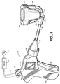
- the sanitizer 10 of the invention as seen in Fig. 1 includes a manually graspable pistol-like handle 11 and a pivotable trigger 12.
- a threaded stub 11b extends angularly, rearwardly and upwardly from a top 11a of the handle.
- a threaded strain relief connector 15 is affixed to stub 11b.
- a sanitizing fluid tube 16 extends from a fluid source supply S(7) pressurized by an electric pump.
- a proportioning valve 17 is settable to supply a fixed volume of sanitizing fluid to the sanitizer 10.
- the pre-selected volume is from about 3 milliliters to about 15 milliliters. The volume is determined by the setting of a ball spacer seat (Fig.
- a poppet valve 60 shown in Fig. 5 is operable by trigger 12 and permits the flow of sanitizer fluid from valve 17 through a flexible hose 16 into the handle 11 and out a rigid tube 20, preferably of stainless steel, extending from the poppet valve outlet.
- the tube 20 extends through a nozzle-like end 18 of the handle screwed into handle 11 by annular screw connector 19. Flow is provided into an overflow chamber 23 and teat cup 21.
- the flexible hose 16 is preferably constructed of polyvinylchloride (PVC) plastic.
- portions 22a and 22b are separate and integral molded plastic extensions, respectively, extending from the cup which support tube 20. Fixed pin 33 prevents rotation of the cup.
- the cup is angled back at about from 92° to about 98° from the longitudinal axis of the tube as the tube passes through portion 22a to allow for faster and more efficient placement of the cup under a teat.
- the cup and the integral portions 22a and 22b preferably are made of polypropylene plastic.
- the overflow chamber is formed by a clipped-on plastic cover made of Kayton® plastic forming an inverted annular combined splash guard and teat guide 32 having an outer tapered conical wall 23a which aids in guiding the teat 30 into cup cavity 24, an inner wall 23b which prevents splashing and for directing sanitizing fluid being conveyed through tube 20 into the cup 21, an integral top 23d and a cylindrical outer rim 23c.
- An open annulus 28 is formed between the distal bottom end of wall 23a, 23b and a flared upper surface 25 extending from the fluid-holding cavity 24 of the cup 21.
- the cavity is preferably in the shape of an open prolate ellipsoid.
- Tube 20 is sealed in a through-bore 26 in cup extension 22b.
- An integral upper cylindrical rim 27 extends upwardly from the flared upper surface 25 over which the inverted annular splash guard and teat guide 32 is snapped.
- a cylindrical snap ridge 34 with or without a and snap groove may extend between the splash and teat guide 32 and the cup rim 27 or a friction fit provided.
- the handle trigger 12 is pulled releasing a predetermined volume of sanitizing fluid through nozzle end 18.
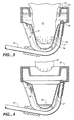
- the fluid flows through tube 20 under pressure from the electric pump for example through a flow restricter 26a into the overflow chamber 23 and then into cup cavity 24 all as shown by the arrows in Fig. 2.
- the cup initially will contain about 5 millimeters of sanitizing fluid 9 up to a level 29 in the fluid-holding cavity 24 of the cup prior to lifting and moving the sanitizer and its cup up to encompass the depending bovine teat 30.
- An orifice 5 for entry of the teat is formed by the inside diameter of guide top 23d.
- the sanitizer can be operated with the user standing either in a cow barn parlor or on a barn floor level.
- This action tends to both kill bacteria at these locations and to actually flush the strep canal and epidermal tissue and folds.
- the flushing action also effectively cleans the teat of any attached mud or manure.
- the sanitizing fluid fully wets the teat as indicated at 9b and after the dropping and removal of the cup, stays on the teat for about two to five minutes before milking. Any excess of fluid remaining on the teat at that time can be removed by a clean one-time paper wipe.
- the above operation is repeated for the three remaining teats such that after the treatment of the fourth teat 30 only a minuscule amount 9d remains in the cup as seen in Fig. 4.
- each teat is again treated by use of the apparatus 10 having an initial volume of 3-6 ml. of sanitizing fluid in the cup cavity 24, affording high mastitis protection for about an hour after milking. By that time the sphincter has closed and the likelihood of infection is minimized.
- Fig. 5 shows an interior view of one-half of the molded plastic casing of handle 11.
- the other half of the casing 40 is a mirror image of the half shown i.e. the casing is made of two longitudinal halves with an abutment line bisecting stub 11b and a longitudinal medial line at the handle bottom.
- the connector 15 functions not only to provide a strain relief for hose 16 but also acts to hold the handle halves together along with bolts and nuts or screw (not shown) passing through screw bosses 41 in the handle halves.
- the coupling union or connector 19 preferably has a thread length equal to the number of threads 43 on the handle nozzle end 18 so that the connector 19 is hand-turned to cinch up the connector.
- a flared end of tube 20 contacts and seals the O-ring 19a. This properly orients the cup 21 upwardly in a direction forwardly generally parallel to the angled connector 15.
- the poppet valve 60 extends into cavity 44 while cylindrical webs of the valve 60 fit into and are supported by holding webs 45, 46 and 47, thus not placing any stresses on the valve operational mechanisms nor on the plastic threaded areas. Threads 42 are provided on the stub 11b.
- Fig. 5 also illustrates schematically the poppet valve 60 including a housing 80 which includes a barbed entry port 61 for receiving an ID of the distal end of the hose 16 extending into handle 11 (Fig. 1); a fluid entry chamber 62 and a movable poppet 63 in a parallel chamber 64.
- the poppet includes an activating spring 65 abutting a closed end bore cap 81, a peripheral groove 66 for receiving a trigger sear 140, which poppet is operable to open or close an orifice 67 in a stub 68, fixed in web 45 within nozzle end 18.
- An O-ring 69 is provided on a conical end 70 of the poppet 66 and an O-ring 71 provided on the cylindrical surface 72.
- Fig. 1 Pulling of the ON-OFF intermittent flow trigger 12 (Fig. 1) pulls the poppet 66 back to compress spring 65 which opens up orifice 67 which allows the indicated-by-arrows flow of sanitizing fluid from the valve 17 through bore 68a (arrow 85) to the tube 20 and cup 21. Release of the trigger pivoted about pins 120 allows the spring to expand pushing the conical end 70 of poppet 66 against a tapered seat on the inner end of stub 68 and against O-ring 69 stopping the flow of fluid from the sanitizer gun.
- Fig. 6 shows the interaction and position of trigger sear 140 in the groove 66 formed in poppet 63.
- FIG. 8 illustrates how the sear 140 extending inwardly from both inner sides of the two leg yoke 110 interfit with grooves 66 of the poppet 63. Legs 110 are expanded so as to push onto pivot pins 120 such that pivot movement of trigger 12 compresses spring 65 to open the poppet valve.
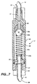
- FIG. 7 shows the proportioning valve 17 which may be employed as part of the sanitizing system.
- a valve housing 50 includes an entry port 51 which permits flow from supply source S (Fig. 1).
- a supply tube is clamped into a threaded valve boss 53.
- a movable valve seat and a removable spacer(s) 56 of various thicknesses is provided inside the entry port.
- a sealing ball 55 is positioned within housing 50 and is movable to position 55a by action of a biasing spring 58, to be sealed against seat 56a of the spacer 56.
- a 3 mil clearance between the ball and interior wall of the housing 50 gives a 3 mil to 15 mil volume of sanitizing fluid, dependent on the vertical level portion of the seat 56a of spacer 56 which is dependent on the thickness of the selected spacer 56.
- the spaced thickness is determinative of the predetermined volume of fluid to be supplied by the triggering of the poppet valve by trigger 12.
- a second ball seat is provided on an end closure 57 at the bottom of the housing 50, the closure having an exit port 52.
- a threaded boss 54 attaches flexible hose 16.
- the seat of closure 57 has a radial bleed passage 57a which functions to allow fluid to flow past the seat to break vacuum so the ball will reseat back on seat 56a.
- the fluid supply 7 is pressurized so as, upon opening of the poppet valve 60, to allow the ball 55 to be forced down off seat 56a to position 55c against the seat of closure 57, while compressing spring 58.
- a metered proportional supply of fluid is fed through the poppet valve 60 and to cup cavity 24.
Landscapes
- Health & Medical Sciences (AREA)
- Veterinary Medicine (AREA)
- Life Sciences & Earth Sciences (AREA)
- Animal Behavior & Ethology (AREA)
- Wood Science & Technology (AREA)
- Zoology (AREA)
- Engineering & Computer Science (AREA)
- General Health & Medical Sciences (AREA)
- Public Health (AREA)
- Surgery (AREA)
- Devices For Dispensing Beverages (AREA)
- Catching Or Destruction (AREA)
- Apparatus For Disinfection Or Sterilisation (AREA)
- Agricultural Chemicals And Associated Chemicals (AREA)
- Cleaning In General (AREA)
Claims (12)
- Appareil de désinfection de tétine de vache (10) comprenant une coupelle de réception de tétine (21) dimensionnée pour recevoir une tétine de vache, et une alimentation de fluide de désinfection (7) comprenant :dans lequel ladite poignée (11) et ladite coupelle (21) sont adaptées pour être manipulées de manière à englober généralement une tétine de vache dépendante dans ladite coupelle (21) ; caractérisé en ce que la chambre de trop-plein (23) comporte une paroi conique effilée (23a) pour guider une tétine de vache dépendante dans la coupelle de réception de tétine (21).une poignée pouvant être tenue manuellement (11), ladite poignée (11) pouvant être connectée à l'alimentation de fluide de désinfection (7) ;la coupelle de réception de tétine (21) étant en ligne et comportant un fond fermé, une partie d'admission supérieure et une chambre de trop-plein supérieure (23) ; etune conduite d'écoulement de fluide de désinfection (20) s'étendant depuis ladite poignée (11) jusqu'à la partie d'admission supérieure de ladite coupelle (21) pour acheminer une quantité prédéterminée de fluide de désinfection (9) depuis l'alimentation de fluide (7) jusque dans ladite coupelle (21) ; et
- Appareil de désinfection de tétine de vache (10) selon la revendication 1, dans lequel ladite poignée (11) est connectée à l'alimentation de fluide (7) par un tuyau souple (16) s'étendant depuis un réservoir d'alimentation de fluide jusqu'à ladite poignée.
- Appareil de désinfection de tétine de vache (10) selon la revendication 1, dans lequel ladite poignée (11) à la forme d'un pistolet et comporte un orifice d'entrée de fluide de désinfection (11b) à proximité d'une surface supérieure (11a) de celle-ci pouvant être connecté par un tuyau souple (16) à ladite alimentation de fluide (7).
- Appareil de désinfection de tétine de vache (10) selon la revendication 1, dans lequel ladite poignée (11) comporte une vanne de commande de fluide (60) pour fournir un écoulement intermittent de la quantité prédéterminée de fluide de désinfection (9) à ladite coupelle (21) ; et dans lequel ladite poignée (11) comporte un déclencheur par préhension (12) pour actionner manuellement ladite tension de commande de fluide (60).
- Appareil de désinfection (10) selon la revendication 4, dans lequel ladite vanne de commande (60) est une vanne à champignon.
- Appareil de désinfection (10) selon la revendication 1, dans lequel ladite poignée (11) a la forme d'un pistolet et ladite conduite d'écoulement de fluide (20) est un tube non souple connecté à une extrémité distale (18) de ladite poignée de tube (11) et dans lequel ladite coupelle (21) est connectée audit tube (20).
- Appareil de désinfection (10) selon la revendication 6, dans lequel ladite coupelle (21) a un axe central vertical incliné en arrière à un angle d'environ 92° à environ 98° par rapport à un axe longitudinal dudit tube (20).
- Appareil de désinfection (10) selon la revendication 1, dans lequel ladite coupelle (21) comporte une cavité inférieure (24) en forme générale de moitié inférieure d'ellipsoïde de révolution aplati ouvert.
- Appareil de désinfection (10) selon la revendication 1, dans lequel ladite chambre de trop-plein de coupelle (23) est toroïdale et bornée intérieurement par un écran anti-éclaboussure annulaire inversé et guide de tétine (32) pour diriger l'écoulement de fluide de désinfection depuis ladite partie d'admission de coupelle jusque dans ladite chambre de trop-plein (23) et jusque dans ladite cavité (24) et pour guider une tétine de vache dépendante dans ladite cavité (24), ladite chambre de trop-plein (23) recevant le fluide de désinfection usagé (9) déplacé depuis ladite cavité (24) par insertion d'une tétine de vache dans ladite cavité (24).
- Appareil de désinfection (10) selon la revendication 1, dans lequel ladite coupelle (21) comporte une cavité inférieure (24) et dans lequel ladite cavité (24) est dimensionnée pour recevoir une quantité mesurée de fluide de désinfection et dans lequel une tétine insérée déplace le fluide de désinfection (9) se trouvant dans ladite coupelle (21) dans ladite chambre (23), la tétine est enrobée de fluide de désinfection (9) et la tétine est temporairement scellée dans la cavité (24) pour forcer le fluide de désinfection (9) dans un canal de streptocoque et un épiderme de la tétine.
- Appareil de désinfection de tétine de vache (10) selon la revendication 1, comportant en outre une vanne doseuse (17) entre ladite alimentation de fluide (7) et ladite poignée (11), ladite vanne doseuse (17) comprenant un logement de vanne (50), des premier et deuxième sièges de vanne espacés (56a, 57a) dans ledit logement (50), une bille de fermeture (55) pouvant se déplacer entre lesdits sièges de vanne (56a, 57a), et un ressort de charge préliminaire (58) fermant normalement ladite bille (55) contre l'un desdits sièges de vanne (56a, 57a), et dans lequel le déplacement de ladite bille (55) jusqu'à l'autre desdits sièges de vanne (56a, 57a) provoque le déplacement de la quantité prédéterminée de fluide de désinfection (9) depuis l'alimentation de fluide (7).
- Appareil de désinfection (10) selon la revendication 11, dans lequel ledit un desdits sièges de vanne (56a, 57a) est fourni sur une pièce d'écartement amovible (56), l'épaisseur de la pièce d'écartement (56) déterminant la quantité prédéterminée de fluide de désinfection (9) depuis l'alimentation de fluide (7).
Applications Claiming Priority (3)
| Application Number | Priority Date | Filing Date | Title |
|---|---|---|---|
| US250244 | 1994-05-26 | ||
| US08/250,244 US5535700A (en) | 1994-05-26 | 1994-05-26 | Bovine teat sanitizer and method |
| PCT/US1995/006434 WO1995032686A2 (fr) | 1994-05-26 | 1995-05-26 | Procede et dispositif permettant d'apporter des soins hygieniques aux trayons de bovins |
Publications (2)
| Publication Number | Publication Date |
|---|---|
| EP0869748A2 EP0869748A2 (fr) | 1998-10-14 |
| EP0869748B1 true EP0869748B1 (fr) | 2005-04-13 |
Family
ID=22946932
Family Applications (1)
| Application Number | Title | Priority Date | Filing Date |
|---|---|---|---|
| EP95920594A Expired - Lifetime EP0869748B1 (fr) | 1994-05-26 | 1995-05-26 | Dispositif permettant d'apporter des soins hygieniques aux trayons de bovins |
Country Status (7)
| Country | Link |
|---|---|
| US (1) | US5535700A (fr) |
| EP (1) | EP0869748B1 (fr) |
| AU (1) | AU690998B2 (fr) |
| CA (1) | CA2191323C (fr) |
| DE (1) | DE69534145T2 (fr) |
| NZ (1) | NZ287319A (fr) |
| WO (1) | WO1995032686A2 (fr) |
Cited By (1)
| Publication number | Priority date | Publication date | Assignee | Title |
|---|---|---|---|---|
| GB2570630B (en) * | 2017-11-24 | 2020-06-17 | Cotswold Dairy Equipment Company Ltd | A dip cup |
Families Citing this family (21)
| Publication number | Priority date | Publication date | Assignee | Title |
|---|---|---|---|---|
| US5711251A (en) * | 1996-04-03 | 1998-01-27 | Abc Dispensing Technologies, Inc. | Germicide applicator for cow udders |
| RU2158504C1 (ru) * | 1999-07-29 | 2000-11-10 | Кубанский государственный аграрный университет | Устройство для дезинфекции сосков вымени сельскохозяйственных животных |
| US6348206B1 (en) * | 1999-09-27 | 2002-02-19 | Devtech Marketting, Inc. | Composition and method for producing lubricating, germicide foam |
| US6752102B2 (en) * | 1999-09-27 | 2004-06-22 | Pro Chemicals, Llc | Apparatus for producing a foam bovine teat dip |
| US6302058B1 (en) * | 1999-09-27 | 2001-10-16 | North West Environmental Systems, Inc. | Apparatus and method for producing a foam bovine teat dip |
| RU2212788C2 (ru) * | 2000-07-03 | 2003-09-27 | Рязанская государственная сельскохозяйственная академия им. проф. П.А. Костычева | Устройство для дезинфекции сосков вымени после доения |
| IL143549A0 (en) * | 2001-06-04 | 2002-04-21 | Turner Josef | A system for veterinary treatment |
| RU2212789C2 (ru) * | 2001-12-17 | 2003-09-27 | Рязанская государственная сельскохозяйственная академия им. проф. П.А. Костычева | Устройство для орошения сосков вымени животных |
| US6779484B2 (en) * | 2002-07-19 | 2004-08-24 | Fangjiang Guo | Milking system |
| US6935270B2 (en) * | 2003-08-29 | 2005-08-30 | Delaval, Inc. | Milking and application teat cup, system, and method |
| US7165510B2 (en) * | 2003-11-04 | 2007-01-23 | Dennis Lee Hakes | Bovine germicide application device |
| US7389747B2 (en) * | 2004-01-27 | 2008-06-24 | Ruff House, Inc. | Animal or other object washing system and method |
| US20070074673A1 (en) * | 2005-09-30 | 2007-04-05 | Pro-Chemicals Llc | System and method for foaming liquid |
| US7654228B1 (en) * | 2007-01-05 | 2010-02-02 | Sunny Lyn Graham | Paw sucker |
| GB0705478D0 (en) * | 2007-03-22 | 2007-05-02 | Ambic Equip Ltd | Dip cup |
| US7753006B2 (en) * | 2007-09-28 | 2010-07-13 | Ambic Equipment Limited | Teat application device with cup portion having limited circumferential extension |
| GB2473862A (en) * | 2009-09-28 | 2011-03-30 | Ambic Equip Ltd | A teat treatment device with a liquid directing baffle |
| US8534231B2 (en) * | 2009-09-30 | 2013-09-17 | Dennis Lee Hakes | Bovine germicide application technology |
| US20160015000A1 (en) * | 2014-07-21 | 2016-01-21 | Ryan Andew Diez | Handheld animal washing apparatus |
| CN107260358B (zh) * | 2017-05-31 | 2018-12-25 | 重庆市长寿区莲莲奶牛养殖场 | 一种奶牛乳房消毒装置 |
| USD901624S1 (en) | 2018-05-18 | 2020-11-10 | Cotswold Diary Equipment Co Ltd | Disinfectant equipment |
Family Cites Families (6)
| Publication number | Priority date | Publication date | Assignee | Title |
|---|---|---|---|---|
| US2532088A (en) * | 1947-11-01 | 1950-11-28 | Cordis Nat | Cleansing apparatus |
| US3366111A (en) * | 1965-09-15 | 1968-01-30 | American Home Prod | Device for application of medicated liquids to teat skin of female quadrupeds |
| US3648696A (en) * | 1970-03-20 | 1972-03-14 | Robert H Keith | Teat spraying apparatus for aiding in the prevention of mastitis in dairy cows |
| US3921860A (en) * | 1970-12-18 | 1975-11-25 | Silver Jules | Liquid dispensing cup for flexible container |
| US3828776A (en) * | 1972-03-09 | 1974-08-13 | A Sparr | Teat disinfecting cup for use after milking |
| US5379724A (en) * | 1993-07-22 | 1995-01-10 | Babson Bros. Co. | Ultrasound teat dip |
-
1994
- 1994-05-26 US US08/250,244 patent/US5535700A/en not_active Expired - Lifetime
-
1995
- 1995-05-26 NZ NZ287319A patent/NZ287319A/en unknown
- 1995-05-26 DE DE69534145T patent/DE69534145T2/de not_active Expired - Lifetime
- 1995-05-26 WO PCT/US1995/006434 patent/WO1995032686A2/fr not_active Ceased
- 1995-05-26 CA CA002191323A patent/CA2191323C/fr not_active Expired - Fee Related
- 1995-05-26 EP EP95920594A patent/EP0869748B1/fr not_active Expired - Lifetime
- 1995-05-26 AU AU26073/95A patent/AU690998B2/en not_active Ceased
Cited By (1)
| Publication number | Priority date | Publication date | Assignee | Title |
|---|---|---|---|---|
| GB2570630B (en) * | 2017-11-24 | 2020-06-17 | Cotswold Dairy Equipment Company Ltd | A dip cup |
Also Published As
| Publication number | Publication date |
|---|---|
| DE69534145T2 (de) | 2006-02-16 |
| NZ287319A (en) | 1998-09-24 |
| AU690998B2 (en) | 1998-05-07 |
| DE69534145D1 (de) | 2005-05-19 |
| AU2607395A (en) | 1995-12-21 |
| EP0869748A2 (fr) | 1998-10-14 |
| WO1995032686A2 (fr) | 1995-12-07 |
| CA2191323C (fr) | 2000-08-01 |
| US5535700A (en) | 1996-07-16 |
| WO1995032686A3 (fr) | 1996-05-23 |
Similar Documents
| Publication | Publication Date | Title |
|---|---|---|
| US5535700A (en) | Bovine teat sanitizer and method | |
| US7178480B2 (en) | Method of reducing risk of infection of a bovine teat after cessation of milking | |
| US3713423A (en) | Udder and teat cleansing apparatus and sanitizer | |
| JP2529875B2 (ja) | 乳頭の洗滌法、同洗滌装置及び同洗滌装置用のカップ | |
| US9504226B2 (en) | Methods and apparatus for applying teat dip to a dairy animal | |
| US8210123B2 (en) | Teat cup | |
| US20040231603A1 (en) | Device and a method for allowing performance of several separate treatments of a teat of an animal | |
| US7753006B2 (en) | Teat application device with cup portion having limited circumferential extension | |
| US7387086B2 (en) | Bovine germicide application device and method | |
| AU2004270168A1 (en) | Milking and applicator teat cup, system, and method | |
| EP3410846B1 (fr) | Système, manchon et méthode de préparation des trayons | |
| US20020134797A1 (en) | Dispenser for a cleaning medium | |
| US5711251A (en) | Germicide applicator for cow udders | |
| EP1224858B1 (fr) | Applicateur | |
| US20090194034A1 (en) | Teat foam ring | |
| GB2473862A (en) | A teat treatment device with a liquid directing baffle | |
| AU603119B2 (en) | Liquid dispensing system | |
| EP2777387B1 (fr) | Procédés et appareil pour l'application de trempage des trayons d'un animal laitier | |
| JPH06189983A (ja) | 家畜の乳頭清浄用噴霧器 |
Legal Events
| Date | Code | Title | Description |
|---|---|---|---|
| PUAI | Public reference made under article 153(3) epc to a published international application that has entered the european phase |
Free format text: ORIGINAL CODE: 0009012 |
|
| 17P | Request for examination filed |
Effective date: 19961223 |
|
| AK | Designated contracting states |
Kind code of ref document: A2 Designated state(s): BE DE DK ES FR GB IT NL SE |
|
| 17Q | First examination report despatched |
Effective date: 20000216 |
|
| GRAG | Despatch of communication of intention to grant |
Free format text: ORIGINAL CODE: EPIDOS AGRA |
|
| RTI1 | Title (correction) |
Free format text: BOVINE TEAT SANITIZER |
|
| GRAG | Despatch of communication of intention to grant |
Free format text: ORIGINAL CODE: EPIDOS AGRA |
|
| GRAH | Despatch of communication of intention to grant a patent |
Free format text: ORIGINAL CODE: EPIDOS IGRA |
|
| 18D | Application deemed to be withdrawn |
Effective date: 20021203 |
|
| D18D | Application deemed to be withdrawn (deleted) | ||
| GRAS | Grant fee paid |
Free format text: ORIGINAL CODE: EPIDOSNIGR3 |
|
| GRAA | (expected) grant |
Free format text: ORIGINAL CODE: 0009210 |
|
| AK | Designated contracting states |
Kind code of ref document: B1 Designated state(s): BE DE DK ES FR GB IT NL SE |
|
| PG25 | Lapsed in a contracting state [announced via postgrant information from national office to epo] |
Ref country code: ES Free format text: LAPSE BECAUSE OF FAILURE TO SUBMIT A TRANSLATION OF THE DESCRIPTION OR TO PAY THE FEE WITHIN THE PRESCRIBED TIME-LIMIT Effective date: 20050413 |
|
| REF | Corresponds to: |
Ref document number: 69534145 Country of ref document: DE Date of ref document: 20050519 Kind code of ref document: P |
|
| PG25 | Lapsed in a contracting state [announced via postgrant information from national office to epo] |
Ref country code: SE Free format text: LAPSE BECAUSE OF FAILURE TO SUBMIT A TRANSLATION OF THE DESCRIPTION OR TO PAY THE FEE WITHIN THE PRESCRIBED TIME-LIMIT Effective date: 20050713 Ref country code: DK Free format text: LAPSE BECAUSE OF FAILURE TO SUBMIT A TRANSLATION OF THE DESCRIPTION OR TO PAY THE FEE WITHIN THE PRESCRIBED TIME-LIMIT Effective date: 20050713 |
|
| PLBE | No opposition filed within time limit |
Free format text: ORIGINAL CODE: 0009261 |
|
| STAA | Information on the status of an ep patent application or granted ep patent |
Free format text: STATUS: NO OPPOSITION FILED WITHIN TIME LIMIT |
|
| ET | Fr: translation filed | ||
| 26N | No opposition filed |
Effective date: 20060116 |
|
| PGFP | Annual fee paid to national office [announced via postgrant information from national office to epo] |
Ref country code: IT Payment date: 20070627 Year of fee payment: 13 |
|
| PG25 | Lapsed in a contracting state [announced via postgrant information from national office to epo] |
Ref country code: IT Free format text: LAPSE BECAUSE OF NON-PAYMENT OF DUE FEES Effective date: 20080526 |
|
| PGFP | Annual fee paid to national office [announced via postgrant information from national office to epo] |
Ref country code: DE Payment date: 20130522 Year of fee payment: 19 Ref country code: GB Payment date: 20130522 Year of fee payment: 19 |
|
| PGFP | Annual fee paid to national office [announced via postgrant information from national office to epo] |
Ref country code: FR Payment date: 20130531 Year of fee payment: 19 Ref country code: BE Payment date: 20130531 Year of fee payment: 19 Ref country code: NL Payment date: 20130510 Year of fee payment: 19 |
|
| REG | Reference to a national code |
Ref country code: DE Ref legal event code: R119 Ref document number: 69534145 Country of ref document: DE |
|
| REG | Reference to a national code |
Ref country code: NL Ref legal event code: V1 Effective date: 20141201 |
|
| GBPC | Gb: european patent ceased through non-payment of renewal fee |
Effective date: 20140526 |
|
| REG | Reference to a national code |
Ref country code: DE Ref legal event code: R119 Ref document number: 69534145 Country of ref document: DE Effective date: 20141202 |
|
| PG25 | Lapsed in a contracting state [announced via postgrant information from national office to epo] |
Ref country code: NL Free format text: LAPSE BECAUSE OF NON-PAYMENT OF DUE FEES Effective date: 20141201 |
|
| REG | Reference to a national code |
Ref country code: FR Ref legal event code: ST Effective date: 20150130 |
|
| PG25 | Lapsed in a contracting state [announced via postgrant information from national office to epo] |
Ref country code: DE Free format text: LAPSE BECAUSE OF NON-PAYMENT OF DUE FEES Effective date: 20141202 |
|
| PG25 | Lapsed in a contracting state [announced via postgrant information from national office to epo] |
Ref country code: FR Free format text: LAPSE BECAUSE OF NON-PAYMENT OF DUE FEES Effective date: 20140602 Ref country code: GB Free format text: LAPSE BECAUSE OF NON-PAYMENT OF DUE FEES Effective date: 20140526 |
|
| PG25 | Lapsed in a contracting state [announced via postgrant information from national office to epo] |
Ref country code: BE Free format text: LAPSE BECAUSE OF NON-PAYMENT OF DUE FEES Effective date: 20140531 |