EP0869632B1 - Nachrichtenübertragungssystem mit zwei-/vierphasen moduliertem kammförmigen spreizband - Google Patents
Nachrichtenübertragungssystem mit zwei-/vierphasen moduliertem kammförmigen spreizband Download PDFInfo
- Publication number
- EP0869632B1 EP0869632B1 EP19970941182 EP97941182A EP0869632B1 EP 0869632 B1 EP0869632 B1 EP 0869632B1 EP 19970941182 EP19970941182 EP 19970941182 EP 97941182 A EP97941182 A EP 97941182A EP 0869632 B1 EP0869632 B1 EP 0869632B1
- Authority
- EP
- European Patent Office
- Prior art keywords
- phase
- sequence
- signal
- code
- periodic
- Prior art date
- Legal status (The legal status is an assumption and is not a legal conclusion. Google has not performed a legal analysis and makes no representation as to the accuracy of the status listed.)
- Expired - Lifetime
Links
- 238000001228 spectrum Methods 0.000 title claims description 45
- 238000004891 communication Methods 0.000 title claims description 39
- 230000000737 periodic effect Effects 0.000 description 27
- 230000001360 synchronised effect Effects 0.000 description 20
- 238000000034 method Methods 0.000 description 16
- 230000005540 biological transmission Effects 0.000 description 14
- 239000011159 matrix material Substances 0.000 description 9
- 238000005311 autocorrelation function Methods 0.000 description 7
- 238000010276 construction Methods 0.000 description 6
- 238000001514 detection method Methods 0.000 description 6
- 238000005314 correlation function Methods 0.000 description 5
- 238000010586 diagram Methods 0.000 description 5
- 125000004122 cyclic group Chemical group 0.000 description 4
- 238000004519 manufacturing process Methods 0.000 description 4
- 238000000819 phase cycle Methods 0.000 description 4
- 230000000694 effects Effects 0.000 description 2
- 230000003595 spectral effect Effects 0.000 description 2
- 239000013598 vector Substances 0.000 description 2
- 238000005516 engineering process Methods 0.000 description 1
- 230000002349 favourable effect Effects 0.000 description 1
- 230000003014 reinforcing effect Effects 0.000 description 1
- 230000035945 sensitivity Effects 0.000 description 1
- 238000012772 sequence design Methods 0.000 description 1
- 230000001131 transforming effect Effects 0.000 description 1
Images


Classifications
-
- H—ELECTRICITY
- H04—ELECTRIC COMMUNICATION TECHNIQUE
- H04B—TRANSMISSION
- H04B1/00—Details of transmission systems, not covered by a single one of groups H04B3/00 - H04B13/00; Details of transmission systems not characterised by the medium used for transmission
- H04B1/69—Spread spectrum techniques
- H04B1/707—Spread spectrum techniques using direct sequence modulation
- H04B1/709—Correlator structure
- H04B1/7093—Matched filter type
-
- H—ELECTRICITY
- H04—ELECTRIC COMMUNICATION TECHNIQUE
- H04B—TRANSMISSION
- H04B1/00—Details of transmission systems, not covered by a single one of groups H04B3/00 - H04B13/00; Details of transmission systems not characterised by the medium used for transmission
- H04B1/69—Spread spectrum techniques
- H04B1/707—Spread spectrum techniques using direct sequence modulation
- H04B1/7097—Interference-related aspects
-
- H—ELECTRICITY
- H04—ELECTRIC COMMUNICATION TECHNIQUE
- H04J—MULTIPLEX COMMUNICATION
- H04J13/00—Code division multiplex systems
- H04J13/0007—Code type
- H04J2013/0037—Multilevel codes
Definitions
- the present invention relates to a two-phase/four-phase modulated spread spectrum communication system with a comb-form spectrum which is designed so as to reduce co-channel interference.
- the present applicant has announced an approximately synchronized CDMA system that uses signals consisting of pseudo-periodic sequences as a signal design method which makes it possible to avoid co-channel interference.
- signals are designed by using multi-phase sequences; consequently, the signals on respective channels are not two-phase signals (which are signals expressed by +, -) or four-phase signals (which are signals expressed by +, -, j, -j), and therefore, they should be made of much more complicated communication equipment.
- An object of the present invention is to provide a two-phase/four-phase modulated spread spectrum communication system with a comb-form spectrum which makes it possible to simplify the construction of a communication equipment by means of two-phase signals or four-phase signals.
- a further object is to provide a two-phase/four-phase modulated spread spectrum communication system with a comb-form spectrum which makes it possible to assign different carrier waves to respective users by means of two-phase signals or four-phase signals.
- a further object is to provide a two-phase/four-phase modulated spread spectrum communication system with a comb-form spectrum which makes it possible, using two-phase signals or four-phase signals, to prevent the generation of side lobes in the vicinity of the main pulses in signals produced from the matched filter on the reception side.
- a further object is to provide a two-phase/four-phase modulated spread spectrum communication system with a comb-form spectrum which makes it possible to create a plurality of code words by the use of two-phase signals or four-phase signals.
- the present invention is characterised in that a two or four phase code-word belonging to a code-set whose member code-words constitutes super-regular polyhedrons in the signal space is used as said basic sequence; and each of said code-sets assigned to the respective users is produced by multiplying a basic code-set with the user corresponding carrier frequency so that the code-sets assigned to all the users become orthogonal to one another.
- different carrier waves are assigned to respective users.
- These carrier waves and two-phase signal or four-phase signals with a comb-form spectrum are used by respective users to make their extended frames for transmission. Because of the orthogonally of said extended frames, when these extended frames arrive in a receiver, the matched filters for respective users produce main pulses and no side lobes in the vicinity of each of the main pulses.
- the basic sequence is formed as a two-phase or four-phase orthogonal sequence or as a multi-phase orthogonal sequences and side lobes are prevented from being generated in the vicinity of the main pulses produced from the matched filter on the reception side, thus reinforcing the anti-multi-path characteristics.
- Figure 1 is a block diagram which illustrates a communication system using one embodiment of the two-phase/four-phase modulated spread spectrum communication system with a comb-form spectrum provided by the present invention.
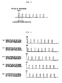
- Figures 2(a) and 2(b) show examples of the spectrum and waveform of the basic signal used in the communication system shown in Figure 1.
- Figure 3 shows an example of the spectrum of the signal obtained by repeating the signal shown in Figure 2.
- Figures 4(a) through 4(e) show examples of the spectra obtained when the signal shown in Figure 3 is transmitted as a carrier wave at various frequencies.
- Figure 5 shows an example of the spectrum of another basic signal used in the communication system shown in Figure 1.
- Figure 6 shows an example of the spectrum of still another basic signal used in the communication system shown in Figure 1.
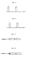
- Figure 7 is a model diagram which shows one example of a signal which acts as the base of a pseudo-periodic signal used in the communication system shown in Figure 1.
- Figure 8 is a model diagram which shows an example of a pseudo-periodic signal based on the signal shown in Figure 7.
- Figure 9 is a model diagram which is used to illustrate the effect of the pseudo-periodic signal shown in Figure 8.
- a two-phase signal or four-phase signal is more useful than a multi-phase signal; accordingly, the design method of a two-phase signal or four-phase signal for use in an approximately synchronized CDMA system will be described in which features of no side lobes in detection and no co-channel interference and, excellent data communication capacity will be explained.
- a two-phase or four-phase sequence is used as a means of carrying information in each set which consists of a transmitter and receiver (generally a base station).
- co-channel interference appears as a multi-phase sequence as far as the carrier means on the receiver is concerned.
- co-channel interference does not affect the sensitivity on the receiver.
- the co-channel interference signal becomes a two-phase signal or four-phase signal as far as the transmitter carrier means is concerned.
- the correlation characteristics of a period sequence are more easily designed than those of a sequence of finite length.
- A (a 0 ,a 1 ,...,a N-1 ) is taken as a sequence of finite length with a length of N which is designed so that this sequence has favorable periodic correlation characteristics
- A' (a N-L1 ,...,a N-1 ,a 0 ,...,a N-1 ,a 0 ,...,a L2-1 ) is taken as an expanded sequence of finite length with a length of N + L 1 + L 2 whose central portion, a portion of length N, coincides with the finite length sequence A.
- the elements of the front-end portion of the finite length sequence A' with a length of L 1 coincide with the elements of the back-end portion of the finite length sequence A with a length of L 1 .
- the elements of the back-end portion of the finite length sequence A' with a length of L 2 coincide with the elements of the front-end portion of the finite length sequence A with a length of L 2 .
- the expanded finite length sequence A' constitutes a finite length sequence which has a pseudo-period of N.
- the output signal with length 2N + L 1 + L 2 - 1 that is produced from this filter corresponds to the correlation function of the finite length sequence A' and the finite length sequence A.
- the central portion of the output signal with a length of L 1 + L 2 + 1 also coincides with the portion extending from the -L 1 shift component to the L 2 shift component of the auto correlation function of the periodic sequence "... AAA ".
- the finite length sequence A' is referred to as a pseudo-periodic sequence with a length of N + L 1 + L 2 .
- the present inventors have proposed a method for setting periodic sequences which do not have correlation. Here, this design method will again be explained.
- a and B be cyclic matrices, each of which represents a periodic sequence, then these matrices A and B are related to diagonal matrices C and D as indicated by the following equations:
- F indicates a DFT (Discrete Fourier transform) matrix.
- B and D are respective complex conjugates of B and D
- ' B is a transposed matrix of B .
- the cross correlation function between the cyclic matrices A and B is zero in all terms.
- each of the column vectors on the right side of Equation (2) is an orthogonal sequence.
- Transforming an orthogonal sequence with DFT makes a (multi-phase) sequences whose components have a certain absolute value, Accordingly, (Continued to next page)
- F 12-point DFT matrix
- each of the four columns in the left-side matrix of Equation (2) is an orthogonal sequence.
- these auto correlation functions have useful characteristics for separating received signal and multi-path noise.
- the column vectors on the right side of Equation (2) are taken as A1, A2, A3 and A4.
- H1 shown in the following equation is a cyclic type unitary matrix.
- the eight columns in the respective matrices shown below constitute a super-regular polyhedron in Euclidean space.
- each pseudo-periodic signal set [y io' , y il' ..., y i7' ] is a four-phase signal set on its own carrier wave.
- signals from undesired transmitters are received as multi-phase signals which do not produce any filter output at the receiver; accordingly, such signals do not produce co-channel interference.
- four-phase orthogonal sequences such as (1, 1, 1, -1), (1, j, 1, -j), (1, 1, 1, 1, 1, 1, j, -1, -j, 1, -1, 1, -1, 1, -j, -1, j) or (1, 1, 1, 1, 1, 1, j, -1, j, 1, -1, 1, -1, 1, j, -1, j), etc, can be used instead of (1, j).
- a two-phase orthogonal sequence 1, 1, 1, -1) can be used in order to set two-phase signals.
- orthogonal sequence F N x i can be used as the basic orthogonal sequence in the above-described Equation (2).
- each of the signals obtained is a two-phase or four-phase signal on its own carrier wave.
- any arbitrarily selected conventional codes can be used for the signal design described so far.
- balanced four-phase signals containing Numerical formula 19 ( 1+j 2 , -1+j 2 , -1-j 2 , 1-j 2 ) can be obtained from unbalanced four-phase signals containing (1, j, -1, -j).
- the balanced four-phase signals may be more suitable than the unbalanced four-phase signals from the standpoint of the construction of the equipment.
- the real-number parts and imaginary-number parts of the balanced four-phase signals respectively consist of two values each, it may be possible to simplify the construction of the equipment depending on the approach used.
- Figure 1 is a block diagram which illustrates one example of a communication system using one embodiment of the two-phase/four-phase modulated spread spectrum communication system with a comb-form spectrum provided by the present invention.
- a basic sequence consisting of two-phase or four-phase tips is prepared on the transmission side, and an expanded transmission frame is constructed by repeatedly arranging the basic sequence so as to make a finite length periodic sequence, and adding one or a plurality of tips of the back portion and front portion of the finite length periodic sequence with a comb-form spectrum, to the outside of the front portion and the outside of the back portion of the finite length periodic sequence; and at the receiver, this expanded transmission frame is demodulated with a matched filter matched to the finite length periodic sequence prior to expansion.
- the signal S 1 be a four-phase signal
- both the real part and the imaginary part will consist of the two values Numerical formula 20 ( 1 2 , -1 2 ) so that a signal can easily be generated with the following components, Numerical formula 21 ( 1+j 2 ,1-j 2 , -1+j 2 , -1-j 2
- a basic sequence for instance signal S 1
- an expanded transmission frame is constructed by repeating one or a plurality of the basic sequence so as to obtain a finite length periodic sequence with a comb-form spectrum and by adding one or a plurality of tips of the back portion and front portion of the finite length periodic sequence to the outside of the front portion and outside of the back portion of the finite length periodic sequence, and at the receiver the expanded transmission frame is demodulated with a matched filter matched to the finite length periodic sequence prior to expansion; it is possible to realize an approximately synchronized interference-free CDMA system by creating a signal A' shown in Figure 8 based upon the signal A of Figure 7, and by transmitting this signal A', and then by demodulating this signal at the receiver with a matched filter matched to the signal A.
- this signal A' will act as an interference signal with respect to a receiver 3 who attempts to receive signal B, e. g., a general receiving station [B] other than receiving station [A].
- signal B e. g., a general receiving station [B] other than receiving station [A].
- the phase at which the receiving station [B] receives signal A constantly fluctuates.
- the receiving station [A] detects only signal A by using a matched filter matched to signal A; and even though when the station [A] receives the portion B" of signal B with the same frame format addressed to the receiving station [B], this does not appear as the output of the matched filter matched to the periodic sequence A. In this way, an approximately synchronized interferencc-free CDMA system can be realized.
- a basic sequence consisting of two-phase or four-phase tips is prepared at the transmitter, and an expanded transmission frame is constructed by repeatedly arranging one or a plurality of the basic sequence to make a finite length periodic sequence with a comb-form spectrum and by adding one or a plurality of tips of the back portion and front portion of the finite length periodic sequence to the outside of the front portion and outside of the back portion of the finite length periodic sequence, and at the receiver side the expanded transmission frame is demodulated with a matched filter matched to the finite length periodic sequence prior to expansion; accordingly, the construction of the communication equipment can be simplified, because a two-phase signal or four-phase signal is used, compared to cases where multi-phase signals are used, and also the manufacturing costs can be reduced.
- a transmitter produces the signal A' on the basis of signal A, which is the object of transmission, and transmits this signal, and receives, demodulates the received signal with a matched filter matched to the signal A, using the above-described communication method and the concept of a "pseudo-periodic sequence", an approximately synchronized interference-free CDMA system can be realized.
- communications are performed using the four-phase signals shown in Equation (3), etc.; however, it is also possible to perform communications using the two-phase signal shown in the following formula: (1,j) or the four-phase signals shown in the formula below, etc.
- (0, 1, 2, 3) corresponds to (exp(j a), exp(j(a + ⁇ /2)), exp(j(a + ⁇ )), exp(j(a + 3 ⁇ /z).
- a signal “S 1 S 1 S 1 S 1 S 1 " is produced by repeating a signal S 1 of an orthogonal sequence in order to realize an interference-free CDMA system.
- the signal S 1 is repeated, the resulting spectrum is a comb-form spectrum, and as a result, it is also possible to produce a transmission signal by repeating a basic sequence signal other than such an orthogonal sequence.
- each component of the comb-form spectrum takes the same amplitude by using the orthogonal sequence signal S 1 , thus insuring desirable properties as a signal for transmission and reception.
- a signal S 1 it is also possible to use a multi-phase orthogonal sequence (which is an orthogonal sequence with a certain absolute value) in stead of such an ordinary orthogonal sequence, so that the side lobes in the vicinity of the main pulses may become zero when the received signal is correlatively detected at the receiver 3.
- the construction of the communication equipment can be simplified as a result of the use of two-phase signals or four-phase signals.
- carrier waves can be assigned to respective users by using two-phase signals or four-phase signals.
Landscapes
- Engineering & Computer Science (AREA)
- Computer Networks & Wireless Communication (AREA)
- Signal Processing (AREA)
- Digital Transmission Methods That Use Modulated Carrier Waves (AREA)
Claims (2)
- Spreizspektrum-Kommunikationssystem (1) mit Sendern (2) und Empfängern (3), wobei jeder der Sender folgendes aufweist: Mittel zum Erstellen einer pseudoperiodischen Sequenz, die hergestellt wird, indem der hintere und der vordere Teil einer grundlegenden Sequenz, die einem Benutzer der grundlegenden Sequenz zugewiesen ist, addiert werden, und
Mittel zum Modulieren der pseudoperiodischen Sequenz durch Übertragen von Daten zur Herstellung eines erweiterten Rahmens und Mittel zum Aussenden des erweiterten Rahmens zu einem Empfänger,
und wobei der Empfänger Mittel zum Demodulieren des von den Sendern empfangenen Signals mit einem angepaßten Filter, das an eine einem gewünschten Benutzer zugewiesene grundlegende Sequenz angepaßt ist, aufweist;
wobei die pseudoperiodische Sequenz hergestellt wird, indem der hintere und der vordere Teil der grundlegenden Sequenz zu einer wiederholten grundlegenden Sequenz addiert werden, indem wiederholt eine oder eine Vielzahl der grundlegenden Sequenz so angeordnet werden, daß die wiederholte grundlegende Sequenz ein Kammform-Spektrum aufweist; dadurch gekennzeichnet, daß die Mittel zum Erstellen einer pseudoperiodischen Sequenz so ausgelegt sind, daß sie ein Zwei- oder Vierphasencodewort, das zu einem Codesatz gehört, dessen zugehörige Codewörter superreguläre Polyeder im Signalraum bilden, als die grundlegende Sequenz benutzen;
und so, daß sie jeden der den jeweiligen Benutzern zugewiesenen Codesätze erzeugen, indem ein grundlegender Codesatz mit der benutzerkorrespondierenden Trägerfrequenz multipliziert wird, so daß die allen Benutzern zugewiesenen Codesätze zueinander orthogonal werden. - Spreizspektrum-Kommunikationssystem nach Anspruch 1, das ferner so ausgelegt ist, daß es einem Benutzer ein Codewort oder plurale Codewörter, die zu den jeweiligen besagten Codesätzen gehören, zu seiner ausschließlichen Verwendung zuweist, um es so anderen Benutzern nicht zu erlauben, dieselben Codewörter zu verwenden.
Applications Claiming Priority (4)
| Application Number | Priority Date | Filing Date | Title |
|---|---|---|---|
| JP27185896 | 1996-09-20 | ||
| JP27185896A JP3145642B2 (ja) | 1996-09-20 | 1996-09-20 | 2相・4相変調スペクトル櫛歯状拡散通信方式 |
| JP271858/96 | 1996-09-20 | ||
| PCT/JP1997/003272 WO1998012831A1 (fr) | 1996-09-20 | 1997-09-17 | Systeme de communication diphase/tetraphase a modulation a spectre en peigne etale |
Publications (3)
| Publication Number | Publication Date |
|---|---|
| EP0869632A1 EP0869632A1 (de) | 1998-10-07 |
| EP0869632A4 EP0869632A4 (de) | 2002-10-23 |
| EP0869632B1 true EP0869632B1 (de) | 2005-11-09 |
Family
ID=17505875
Family Applications (1)
| Application Number | Title | Priority Date | Filing Date |
|---|---|---|---|
| EP19970941182 Expired - Lifetime EP0869632B1 (de) | 1996-09-20 | 1997-09-17 | Nachrichtenübertragungssystem mit zwei-/vierphasen moduliertem kammförmigen spreizband |
Country Status (7)
| Country | Link |
|---|---|
| US (1) | US6421367B1 (de) |
| EP (1) | EP0869632B1 (de) |
| JP (1) | JP3145642B2 (de) |
| CN (1) | CN1091987C (de) |
| AU (1) | AU4318297A (de) |
| DE (1) | DE69734568T2 (de) |
| WO (1) | WO1998012831A1 (de) |
Families Citing this family (12)
| Publication number | Priority date | Publication date | Assignee | Title |
|---|---|---|---|---|
| US6285655B1 (en) | 1997-09-08 | 2001-09-04 | Qualcomm Inc. | Method and apparatus for providing orthogonal spot beams, sectors, and picocells |
| JP3301724B2 (ja) * | 1998-03-13 | 2002-07-15 | 直樹 末広 | 相補系列繰返し変調形櫛の歯状スペクトル通信方式 |
| CN1352840A (zh) * | 1999-04-21 | 2002-06-05 | 末广直树 | 具有导频支援形干扰分离功能的cdma通信方式 |
| JP2001094466A (ja) * | 1999-09-17 | 2001-04-06 | Katsuyoshi Azeyanagi | 無相互相関領域を有する符号系列セットを用いたcdma通信方式 |
| JP3989688B2 (ja) * | 2001-02-26 | 2007-10-10 | クラリオン株式会社 | 無線通信ネットワークシステム |
| CN1201514C (zh) * | 2001-04-18 | 2005-05-11 | 连宇通信有限公司 | 码分多址系统中三进制扩频序列编码的实现方法 |
| JP4276009B2 (ja) | 2003-02-06 | 2009-06-10 | 株式会社エヌ・ティ・ティ・ドコモ | 移動局、基地局、無線伝送プログラム、及び無線伝送方法 |
| JP2006157643A (ja) * | 2004-11-30 | 2006-06-15 | Naoki Suehiro | 無線通信システム、無線通信方法及び通信装置 |
| JP2006173755A (ja) * | 2004-12-13 | 2006-06-29 | Naoki Suehiro | データ通信システム、データ通信装置及びデータ通信方法 |
| US9119165B2 (en) | 2009-09-10 | 2015-08-25 | Nextnav, Llc | Coding in a wide area positioning system (WAPS) |
| US9645249B2 (en) | 2011-06-28 | 2017-05-09 | Nextnav, Llc | Systems and methods for pseudo-random coding |
| WO2013003636A2 (en) * | 2011-06-28 | 2013-01-03 | Nextnav, Llc | Coding in a wide area positioning system (waps) |
-
1996
- 1996-09-20 JP JP27185896A patent/JP3145642B2/ja not_active Expired - Fee Related
-
1997
- 1997-09-17 AU AU43182/97A patent/AU4318297A/en not_active Abandoned
- 1997-09-17 EP EP19970941182 patent/EP0869632B1/de not_active Expired - Lifetime
- 1997-09-17 WO PCT/JP1997/003272 patent/WO1998012831A1/ja not_active Ceased
- 1997-09-17 US US09/077,221 patent/US6421367B1/en not_active Expired - Fee Related
- 1997-09-17 CN CN97191295A patent/CN1091987C/zh not_active Expired - Fee Related
- 1997-09-17 DE DE1997634568 patent/DE69734568T2/de not_active Expired - Fee Related
Also Published As
| Publication number | Publication date |
|---|---|
| US6421367B1 (en) | 2002-07-16 |
| DE69734568D1 (de) | 2005-12-15 |
| CN1091987C (zh) | 2002-10-02 |
| JPH1098444A (ja) | 1998-04-14 |
| WO1998012831A1 (fr) | 1998-03-26 |
| EP0869632A4 (de) | 2002-10-23 |
| AU4318297A (en) | 1998-04-14 |
| CN1205143A (zh) | 1999-01-13 |
| DE69734568T2 (de) | 2006-06-08 |
| JP3145642B2 (ja) | 2001-03-12 |
| EP0869632A1 (de) | 1998-10-07 |
Similar Documents
| Publication | Publication Date | Title |
|---|---|---|
| JP3532556B2 (ja) | 高速データ伝送無線ローカル・エリア・ネットワーク | |
| EP3066781B1 (de) | Funkkommunikationssystem und -verfahren auf basis zeitversetzter wellen | |
| US5463657A (en) | Detection of a multi-sequence spread spectrum signal | |
| US7593531B2 (en) | Methods and systems for transceiving chaotic signals | |
| US8401056B2 (en) | Method and apparatus for packet acquisition | |
| EP0869632A1 (de) | Nachrichtenübertragungssystem mit zwei-/vierphasen moduliertem kammförmigen spreizband | |
| NZ264805A (en) | Generating a spread code for a direct sequence code division multiple access digital transmission system | |
| US8804790B2 (en) | Spread spectrum encoding and decoding | |
| JP3444001B2 (ja) | 符号検出回路 | |
| US20140016676A1 (en) | Spread-spectrum codes generation | |
| US20020122463A1 (en) | Generation of spread-spectrum multiple access codes with zero-correlation windows | |
| EP1037423A1 (de) | Digitales kommunikationssystem, sein sender und empfänger und rahmensynchronisations detektor | |
| EP1745561B1 (de) | Zusätzliche hierarchische präambel zur unterstützung eines fdma-kanals in einem mehrband-ofdm-system | |
| US9094108B2 (en) | Spread-spectrum modulation and demodulation | |
| JP3992436B2 (ja) | 1ビット相関レイク受信機 | |
| CA2184448C (en) | Csk communication system and method for spread spectrum communication | |
| US5663983A (en) | Differentially matched filter for a spread spectrum system | |
| US20080194211A1 (en) | Wireless Communication System, Wireless Communication Method, and Communication Apparatus | |
| USRE41931E1 (en) | Receiver module and receiver formed from several cascaded modules | |
| JP3534796B2 (ja) | スペクトル拡散通信方法、その送信機及び受信機 | |
| JPH10285136A (ja) | スペクトラム拡散無線通信システム | |
| US20060109936A1 (en) | Non-coherent DP-MOK reception process with combination of multiple paths and corresponding receiver | |
| KR100882905B1 (ko) | 곱셈기블록을 이용한 복소필터 및 이를 사용한dbo-css 시스템에서의 정합 필터링 장치, 방법 및dbo-css 수신기 | |
| JPH07264093A (ja) | Sawスペクトル拡散復調器及びその構成方法 | |
| IES84731Y1 (en) | Method and device for designing and communicating with orthogonal codes with good autocorrelation properties |
Legal Events
| Date | Code | Title | Description |
|---|---|---|---|
| PUAI | Public reference made under article 153(3) epc to a published international application that has entered the european phase |
Free format text: ORIGINAL CODE: 0009012 |
|
| 17P | Request for examination filed |
Effective date: 19980605 |
|
| AK | Designated contracting states |
Kind code of ref document: A1 Designated state(s): DE FR GB |
|
| A4 | Supplementary search report drawn up and despatched |
Effective date: 20020905 |
|
| AK | Designated contracting states |
Kind code of ref document: A4 Designated state(s): DE FR GB |
|
| RIC1 | Information provided on ipc code assigned before grant |
Free format text: 7H 04J 13/00 A, 7H 04J 13/02 B |
|
| 17Q | First examination report despatched |
Effective date: 20040119 |
|
| GRAP | Despatch of communication of intention to grant a patent |
Free format text: ORIGINAL CODE: EPIDOSNIGR1 |
|
| GRAS | Grant fee paid |
Free format text: ORIGINAL CODE: EPIDOSNIGR3 |
|
| GRAA | (expected) grant |
Free format text: ORIGINAL CODE: 0009210 |
|
| RAP1 | Party data changed (applicant data changed or rights of an application transferred) |
Owner name: SUEHIRO, NAOKI Owner name: YOKOHAMA TLO COMPANY, LTD. |
|
| AK | Designated contracting states |
Kind code of ref document: B1 Designated state(s): DE FR GB |
|
| REG | Reference to a national code |
Ref country code: GB Ref legal event code: FG4D |
|
| REF | Corresponds to: |
Ref document number: 69734568 Country of ref document: DE Date of ref document: 20051215 Kind code of ref document: P |
|
| ET | Fr: translation filed | ||
| PLBE | No opposition filed within time limit |
Free format text: ORIGINAL CODE: 0009261 |
|
| STAA | Information on the status of an ep patent application or granted ep patent |
Free format text: STATUS: NO OPPOSITION FILED WITHIN TIME LIMIT |
|
| 26N | No opposition filed |
Effective date: 20060810 |
|
| PGFP | Annual fee paid to national office [announced via postgrant information from national office to epo] |
Ref country code: GB Payment date: 20080917 Year of fee payment: 12 |
|
| PGFP | Annual fee paid to national office [announced via postgrant information from national office to epo] |
Ref country code: DE Payment date: 20081002 Year of fee payment: 12 |
|
| PGFP | Annual fee paid to national office [announced via postgrant information from national office to epo] |
Ref country code: FR Payment date: 20080926 Year of fee payment: 12 |
|
| GBPC | Gb: european patent ceased through non-payment of renewal fee |
Effective date: 20090917 |
|
| REG | Reference to a national code |
Ref country code: FR Ref legal event code: ST Effective date: 20100531 |
|
| PG25 | Lapsed in a contracting state [announced via postgrant information from national office to epo] |
Ref country code: FR Free format text: LAPSE BECAUSE OF NON-PAYMENT OF DUE FEES Effective date: 20090930 Ref country code: DE Free format text: LAPSE BECAUSE OF NON-PAYMENT OF DUE FEES Effective date: 20100401 |
|
| PG25 | Lapsed in a contracting state [announced via postgrant information from national office to epo] |
Ref country code: GB Free format text: LAPSE BECAUSE OF NON-PAYMENT OF DUE FEES Effective date: 20090917 |