EP0868356B1 - Crate with display panel decoration - Google Patents
Crate with display panel decoration Download PDFInfo
- Publication number
- EP0868356B1 EP0868356B1 EP96943781A EP96943781A EP0868356B1 EP 0868356 B1 EP0868356 B1 EP 0868356B1 EP 96943781 A EP96943781 A EP 96943781A EP 96943781 A EP96943781 A EP 96943781A EP 0868356 B1 EP0868356 B1 EP 0868356B1
- Authority
- EP
- European Patent Office
- Prior art keywords
- display panel
- tabs
- crate
- grooves
- wall
- Prior art date
- Legal status (The legal status is an assumption and is not a legal conclusion. Google has not performed a legal analysis and makes no representation as to the accuracy of the status listed.)
- Expired - Lifetime
Links
- 238000005034 decoration Methods 0.000 title 1
- 238000000034 method Methods 0.000 claims description 2
- 229920003023 plastic Polymers 0.000 description 4
- 239000004033 plastic Substances 0.000 description 4
- 238000005452 bending Methods 0.000 description 3
- 239000011087 paperboard Substances 0.000 description 2
- 239000000463 material Substances 0.000 description 1
Images


Classifications
-
- B—PERFORMING OPERATIONS; TRANSPORTING
- B65—CONVEYING; PACKING; STORING; HANDLING THIN OR FILAMENTARY MATERIAL
- B65D—CONTAINERS FOR STORAGE OR TRANSPORT OF ARTICLES OR MATERIALS, e.g. BAGS, BARRELS, BOTTLES, BOXES, CANS, CARTONS, CRATES, DRUMS, JARS, TANKS, HOPPERS, FORWARDING CONTAINERS; ACCESSORIES, CLOSURES, OR FITTINGS THEREFOR; PACKAGING ELEMENTS; PACKAGES
- B65D25/00—Details of other kinds or types of rigid or semi-rigid containers
- B65D25/20—External fittings
- B65D25/205—Means for the attachment of labels, cards, coupons or the like
-
- G—PHYSICS
- G09—EDUCATION; CRYPTOGRAPHY; DISPLAY; ADVERTISING; SEALS
- G09F—DISPLAYING; ADVERTISING; SIGNS; LABELS OR NAME-PLATES; SEALS
- G09F3/00—Labels, tag tickets, or similar identification or indication means; Seals; Postage or like stamps
- G09F3/04—Labels, tag tickets, or similar identification or indication means; Seals; Postage or like stamps to be fastened or secured by the material of the label itself, e.g. by thermo-adhesion
Definitions
- This invention relates to a crate for carrying articles, for example bottles, which is furnished with a detachable display panel on one or more of its sides or end walls.
- a detachable display panel on one or more of its sides or end walls.
- BE 905329A illustrates a crate having a display panel connected to at least one wall of the crate by the engagement of locking tabs formed in comers of the display panels with corresponding locking apertures formed in the wall.
- One aspect of the invention provides a crate for carrying articles, such as bottles, comprising at least one wall having a display panel detachably connected to said wall, wherein said wall is formed with a plurality of locking apertures spaced apart, each of said locking apertures receiving one of a corresponding group of locking tabs provided on at least one edge of the display panel which is thereby detachably connected to said wall characterised in that said wall is provided with a plurality of grooves and wherein each of said grooves receives another edge of the display panel.
- the display panel may be rectilinear and wherein said locking tabs may protrude from opposing sides of said display panel, the distance between said tabs along one side being greater then the distance between tabs along the opposing side.
- each of the grooves may be attached to a lip on its outer surface, said lip is adapted to guide said display panel into position.
- each of the grooves and/or the apertures may be positioned so that said display panel is maintained in a substantially flat relationship against said wall.
- the locking tabs may be located along upper and lower edges of said display panel each facing away from said display panel.
- each of the grooves may be positioned to support the side edges of said display panel.
- the locking tabs located along the lower edges of said display panel may protrude a greater distance than the locking tabs located along the upper edges of the display panel thereby enabling the lower edge tabs to be maintained in their respective locking apertures when the locking tabs protruding from the upper edges are located in their corresponding apertures.
- Another aspect of the invention provides a method of detachably connecting a display panel to the at least one wall of the crate characterised in that the blank is bent to compress the side edges, and the lower edge being pushed into a face to face relationship with the crate wall until lower tabs are engaged with corresponding apertures, the grooves then act as guides to assist in slotting side edges into their respective grooves, the upper edge tabs are brought into contact with their respective apertures and locked into position.
- a third aspect of the invention provides a display panel for use with a crate of the invention described herein, which display panel is rectilinear and wherein a plurality of locking tabs protrude from opposing sides of the display panel, the distance between the tabs along one side being greater than the distance between tabs along the opposing side.
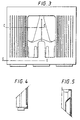
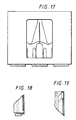
- a rectilinear blank 10 of paperboard or other suitable material for forming a display panel is formed with locking tabs 12,14,16,18 protruding from upper and lower edges of the blank.
- the locking tabs are of known form.
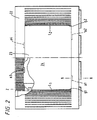
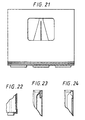
- FIG. 2 Illustrated in Figure 2 is a plastics bottle crate 20 which has in one or more of its end and/or side walls 22, a caved section 23 to receive the blank 10.
- Caved section 23 contains four locking apertures a1, a2, a3, a4 spaced apart so that they can receive locking tabs 12, 14, 16, 18 respectively.
- the size and/or shape of the display panel can be varied according to particular requirements.
- the selection of the position and number of locking tabs on the blank can also be varied to enable the blank to be positioned in a face to face relationship with the caved section panel 24.
- the distance d1 between tabs positioned on the lower edge of the blank 10 is greater than the distance d2 between tabs located along the upper edge of blank 10.
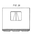
- the side edges of the display panel are positioned within grooves g1, g2 located within the caved section, as shown in Figure 2.
- the grooves maintain the display panel in a flat relationship within the caved section and assist in minimising amount of display panel bending, once in use.
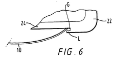
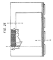
- the display panel is attached to one or more of the crate sides or end walls, by bending the carton and using lips L1 and L2 illustrated in Figure 2, to channel the display panel and lower edge locking tabs 12,14 towards apertures a1, a2. Locking tabs 12,14 are then inserted into their respective apertures a1, a2. Lips L1, L2 maintain the carton in a bent form and guide the side edges s1, s2 shown in Figure 1 into the grooves g1, g2 respectively while the display panel is being channelled into the correct position. Once side edges s1 and s2 are located in grooves g1 and g2 respectively, as illustrated in Figure 6 the upper locking tabs 16, 18 are located into their respective apertures a3, a4.
- locking tabs 12, 14 extending from the lower edge are longer than locking tabs 16,18 extending from the upper edge, to ensure that when the upper edge locking tabs are moved into a final position, locking tabs 12, 14 (already in position) are not disengaged from locking apertures a1, a2, thereby dislodging the display panel.
- the display panels can be readily removed from the crate walls, e.g. by vacuum cups which usually results in the locking tabs tearing off when the panel is removed.
- locking tabs and/or locking apertures are envisaged. Equally, the type and number of grooves or the display panel are not limited to the embodiments illustrated. However, by this arrangement advertising, identification or other data can be applied to the crate and is replaceable when a different display of information is required or if through general wear and tear and the attached display panel has become damaged or soiled and therefore requires replacement.
Landscapes
- Engineering & Computer Science (AREA)
- Physics & Mathematics (AREA)
- General Physics & Mathematics (AREA)
- Theoretical Computer Science (AREA)
- Mechanical Engineering (AREA)
- Details Of Rigid Or Semi-Rigid Containers (AREA)
- Display Devices Of Pinball Game Machines (AREA)
- Developing Agents For Electrophotography (AREA)
- Packaging For Recording Disks (AREA)
- Packaging Frangible Articles (AREA)
Abstract
Description
Claims (9)
- A crate for carrying articles, such as bottles, comprising at least one wall having a display panel (10) detachably connected to said wall, wherein said wall is formed with a plurality of locking apertures (a1, a2, a3, a4) spaced apart, each of said locking apertures receiving one of a corresponding group of locking tabs provided on at least one edge of the display panel which is thereby detachably connected to said wall characterised in that said wall is provided with a plurality of grooves (g1, g2) and wherein each of said grooves receives another edge (s1, s2) of the display panel.
- A crate according to claim 1, wherein said display panel (10) is rectilinear and wherein said locking tabs (12, 14, 16, 18) protrude from opposing sides of said display panel, the distance between said tabs along one side being greater than the distance between tabs along the opposing side.
- A crate according to claim 1 or claim 2 wherein each of said grooves (g1, g2) is attached to a lip (L1, L2) on its outer surface, said lip (L1, L2) is adapted to guide said display panel into position.
- A crate according to any of claims 1 to 3 wherein each of said grooves (g1, g2) and/or said apertures (a1,a2,a3,a4) are positioned so that said display panel (10) is maintained in a substantially flat relationship against said wall.
- A crate according to any of claims 1 to 4 wherein said locking tabs (12, 14, 16, 18) are located along upper and lower edges of said display panel (10) each facing away from said display panel.
- A crate according to any preceding claim wherein each of said grooves (g1, g2) is positioned to support the side edges of said display panel.
- A crate according to claim 5 or claim 6 wherein said locking tabs (12, 14) located along the lower edges of said display panel protrude a greater distance than the locking tabs (12, 18) located along the upper edges of the display panel (10) thereby enabling the lower edge tabs (12, 14) to be maintained in their respective locking apertures (a1, a2) when the locking tabs (16, 18) protruding from the upper edges are located in their corresponding apertures (a3,a4).
- A method of detachably connecting a display panel (10) to the at least one wall (20, 22) of the crate of claims 5 and 6, characterised in that the blank is bent to compress the side edges (s1, s2), and the lower edge being pushed into a face to face relationship with the crate wall until lower tabs (12, 14) are engaged with corresponding apertures (a1,a2,) the grooves (g1, g2) then act as guides to assist in slotting side edges (s1, s2) into their respective grooves, the upper edge tabs (16, 18) are brought into contact with their respective apertures (a3,a4) and locked into position.
- A display panel (10) for use with the crate as defined in any one of claims 2 to 7, which display panel (10) is rectilinear and wherein a plurality of locking tabs (12, 14, 16, 18) protrude from opposing sides of said display panel, the distance between said tabs along one side being greater than the distance between tabs along the opposing side.
Applications Claiming Priority (3)
| Application Number | Priority Date | Filing Date | Title |
|---|---|---|---|
| GBGB9525718.4A GB9525718D0 (en) | 1995-12-15 | 1995-12-15 | Crate with display panel decoration |
| GB9525718 | 1995-12-15 | ||
| PCT/US1996/020073 WO1997021599A1 (en) | 1995-12-15 | 1996-12-14 | Crate with display panel decoration |
Publications (2)
| Publication Number | Publication Date |
|---|---|
| EP0868356A1 EP0868356A1 (en) | 1998-10-07 |
| EP0868356B1 true EP0868356B1 (en) | 2001-10-04 |
Family
ID=10785522
Family Applications (1)
| Application Number | Title | Priority Date | Filing Date |
|---|---|---|---|
| EP96943781A Expired - Lifetime EP0868356B1 (en) | 1995-12-15 | 1996-12-14 | Crate with display panel decoration |
Country Status (9)
| Country | Link |
|---|---|
| EP (1) | EP0868356B1 (en) |
| AT (1) | ATE206378T1 (en) |
| AU (1) | AU1293097A (en) |
| DE (1) | DE69615703T2 (en) |
| DK (1) | DK0868356T3 (en) |
| ES (1) | ES2165535T3 (en) |
| GB (1) | GB9525718D0 (en) |
| PT (1) | PT868356E (en) |
| WO (1) | WO1997021599A1 (en) |
Families Citing this family (4)
| Publication number | Priority date | Publication date | Assignee | Title |
|---|---|---|---|---|
| DE20215400U1 (en) * | 2002-10-07 | 2004-02-19 | Fürstlich Fürstenbergische Brauerei KG | Bottle crate has two or four hollow transparent liquid filled sides in which advertising or decorative material is floated and four carrying handles |
| EP1623929A1 (en) * | 2004-08-05 | 2006-02-08 | Befa GmbH Handelsgesellschaft | Printed sheet as an information element for a ready-to-serve meal package, in particular a package for a pizza |
| US9095249B2 (en) | 2010-04-08 | 2015-08-04 | Miguel Pujadas, S.A. | Dishwasher tray |
| ES1072252Y (en) * | 2010-04-08 | 2010-09-10 | Miquel Pujadas S A | LAVAPLATOS TRAY |
Family Cites Families (3)
| Publication number | Priority date | Publication date | Assignee | Title |
|---|---|---|---|---|
| NL8502335A (en) * | 1985-08-26 | 1987-03-16 | Unilever Nv | Crate for bottles with exchangeable cardboard panel - has quick-fit attachments which allow removal of publicity panel as required |
| NL9301655A (en) * | 1993-09-24 | 1995-04-18 | Dynoplast Bv | Plastic holder, provided with a peripheral edge with a space for a flexible card. |
| DE29511972U1 (en) * | 1995-07-25 | 1995-10-05 | Franz Delbrouck GmbH, 58710 Menden | Cuboid box made of plastic |
-
1995
- 1995-12-15 GB GBGB9525718.4A patent/GB9525718D0/en active Pending
-
1996
- 1996-12-14 AU AU12930/97A patent/AU1293097A/en not_active Abandoned
- 1996-12-14 AT AT96943781T patent/ATE206378T1/en not_active IP Right Cessation
- 1996-12-14 ES ES96943781T patent/ES2165535T3/en not_active Expired - Lifetime
- 1996-12-14 DE DE69615703T patent/DE69615703T2/en not_active Expired - Fee Related
- 1996-12-14 EP EP96943781A patent/EP0868356B1/en not_active Expired - Lifetime
- 1996-12-14 DK DK96943781T patent/DK0868356T3/en active
- 1996-12-14 PT PT96943781T patent/PT868356E/en unknown
- 1996-12-14 WO PCT/US1996/020073 patent/WO1997021599A1/en not_active Ceased
Also Published As
| Publication number | Publication date |
|---|---|
| WO1997021599A1 (en) | 1997-06-19 |
| GB9525718D0 (en) | 1996-02-14 |
| ES2165535T3 (en) | 2002-03-16 |
| EP0868356A1 (en) | 1998-10-07 |
| DE69615703D1 (en) | 2001-11-08 |
| DK0868356T3 (en) | 2001-11-19 |
| DE69615703T2 (en) | 2002-05-29 |
| PT868356E (en) | 2002-01-30 |
| AU1293097A (en) | 1997-07-03 |
| ATE206378T1 (en) | 2001-10-15 |
Similar Documents
| Publication | Publication Date | Title |
|---|---|---|
| US6363645B1 (en) | Insert for display panels | |
| US6523689B2 (en) | Reclosable container with removable backing card | |
| AU1567599A (en) | Case for products such as moist wipes | |
| IL89470A0 (en) | Method and machine for forming cases with polygonal section made from a sheet material and cases thus obtained | |
| TW357130B (en) | Carton and a handle therefor | |
| US3659774A (en) | Composite carrying case | |
| US20030146270A1 (en) | Display packaging | |
| EP1220803B1 (en) | Rigid carton of cigarettes partially openable for display | |
| US6116424A (en) | Bag dispenser | |
| EP0950617A3 (en) | Wrap-around carton | |
| NO302612B1 (en) | Plate for stabilizing a group of identical boxes | |
| AU6518400A (en) | Easy-to-open display container | |
| EP0868356B1 (en) | Crate with display panel decoration | |
| US5524750A (en) | Card holder for container | |
| MXPA96003090A (en) | Support of cards for recipe | |
| MXPA03011934A (en) | Calendar slide. | |
| ES2090406T3 (en) | OPENING STRUCTURE FOR CARDBOARD BOX FOR WEDGE SHAPED CAKE. | |
| EP1004519A1 (en) | Container carrier | |
| CA2380588A1 (en) | Dispensing carton for paper sheet products | |
| JPH05338644A (en) | Packaging container for exhibition and sale, and manufacture thereof | |
| HUT66880A (en) | Unit package for packing and selling objects of small size especially office supplies | |
| US20210387764A1 (en) | Package Covers and Associated Assemblies and Methods | |
| USD1086279S1 (en) | Gift card | |
| JP2023161893A (en) | cardboard container | |
| EP1232097B1 (en) | Packaging for bottle |
Legal Events
| Date | Code | Title | Description |
|---|---|---|---|
| PUAI | Public reference made under article 153(3) epc to a published international application that has entered the european phase |
Free format text: ORIGINAL CODE: 0009012 |
|
| 17P | Request for examination filed |
Effective date: 19980714 |
|
| AK | Designated contracting states |
Kind code of ref document: A1 Designated state(s): AT BE CH DE DK ES FI FR GB GR IE IT LI NL PT SE |
|
| 17Q | First examination report despatched |
Effective date: 19990421 |
|
| GRAG | Despatch of communication of intention to grant |
Free format text: ORIGINAL CODE: EPIDOS AGRA |
|
| GRAG | Despatch of communication of intention to grant |
Free format text: ORIGINAL CODE: EPIDOS AGRA |
|
| GRAH | Despatch of communication of intention to grant a patent |
Free format text: ORIGINAL CODE: EPIDOS IGRA |
|
| GRAG | Despatch of communication of intention to grant |
Free format text: ORIGINAL CODE: EPIDOS AGRA |
|
| GRAH | Despatch of communication of intention to grant a patent |
Free format text: ORIGINAL CODE: EPIDOS IGRA |
|
| GRAH | Despatch of communication of intention to grant a patent |
Free format text: ORIGINAL CODE: EPIDOS IGRA |
|
| GRAA | (expected) grant |
Free format text: ORIGINAL CODE: 0009210 |
|
| AK | Designated contracting states |
Kind code of ref document: B1 Designated state(s): AT BE CH DE DK ES FI FR GB GR IE IT LI NL PT SE |
|
| REF | Corresponds to: |
Ref document number: 206378 Country of ref document: AT Date of ref document: 20011015 Kind code of ref document: T |
|
| REG | Reference to a national code |
Ref country code: CH Ref legal event code: NV Representative=s name: KIRKER & CIE SA Ref country code: CH Ref legal event code: EP |
|
| REF | Corresponds to: |
Ref document number: 69615703 Country of ref document: DE Date of ref document: 20011108 |
|
| REG | Reference to a national code |
Ref country code: IE Ref legal event code: FG4D |
|
| REG | Reference to a national code |
Ref country code: DK Ref legal event code: T3 |
|
| ET | Fr: translation filed | ||
| REG | Reference to a national code |
Ref country code: GB Ref legal event code: IF02 |
|
| REG | Reference to a national code |
Ref country code: PT Ref legal event code: SC4A Free format text: AVAILABILITY OF NATIONAL TRANSLATION Effective date: 20011016 |
|
| REG | Reference to a national code |
Ref country code: ES Ref legal event code: FG2A Ref document number: 2165535 Country of ref document: ES Kind code of ref document: T3 |
|
| REG | Reference to a national code |
Ref country code: GR Ref legal event code: EP Ref document number: 20010402564 Country of ref document: GR |
|
| PLBE | No opposition filed within time limit |
Free format text: ORIGINAL CODE: 0009261 |
|
| STAA | Information on the status of an ep patent application or granted ep patent |
Free format text: STATUS: NO OPPOSITION FILED WITHIN TIME LIMIT |
|
| 26N | No opposition filed | ||
| PGFP | Annual fee paid to national office [announced via postgrant information from national office to epo] |
Ref country code: AT Payment date: 20031106 Year of fee payment: 8 |
|
| PGFP | Annual fee paid to national office [announced via postgrant information from national office to epo] |
Ref country code: FR Payment date: 20031110 Year of fee payment: 8 |
|
| PGFP | Annual fee paid to national office [announced via postgrant information from national office to epo] |
Ref country code: DK Payment date: 20031111 Year of fee payment: 8 |
|
| PGFP | Annual fee paid to national office [announced via postgrant information from national office to epo] |
Ref country code: FI Payment date: 20031114 Year of fee payment: 8 |
|
| PGFP | Annual fee paid to national office [announced via postgrant information from national office to epo] |
Ref country code: NL Payment date: 20031117 Year of fee payment: 8 Ref country code: CH Payment date: 20031117 Year of fee payment: 8 |
|
| PGFP | Annual fee paid to national office [announced via postgrant information from national office to epo] |
Ref country code: SE Payment date: 20031118 Year of fee payment: 8 Ref country code: PT Payment date: 20031118 Year of fee payment: 8 Ref country code: GB Payment date: 20031118 Year of fee payment: 8 |
|
| PGFP | Annual fee paid to national office [announced via postgrant information from national office to epo] |
Ref country code: IE Payment date: 20031120 Year of fee payment: 8 |
|
| PGFP | Annual fee paid to national office [announced via postgrant information from national office to epo] |
Ref country code: DE Payment date: 20031125 Year of fee payment: 8 |
|
| PGFP | Annual fee paid to national office [announced via postgrant information from national office to epo] |
Ref country code: GR Payment date: 20031127 Year of fee payment: 8 |
|
| PGFP | Annual fee paid to national office [announced via postgrant information from national office to epo] |
Ref country code: ES Payment date: 20031205 Year of fee payment: 8 |
|
| PGFP | Annual fee paid to national office [announced via postgrant information from national office to epo] |
Ref country code: BE Payment date: 20031217 Year of fee payment: 8 |
|
| PG25 | Lapsed in a contracting state [announced via postgrant information from national office to epo] |
Ref country code: FI Free format text: LAPSE BECAUSE OF NON-PAYMENT OF DUE FEES Effective date: 20041204 |
|
| PG25 | Lapsed in a contracting state [announced via postgrant information from national office to epo] |
Ref country code: IE Free format text: LAPSE BECAUSE OF NON-PAYMENT OF DUE FEES Effective date: 20041214 Ref country code: GB Free format text: LAPSE BECAUSE OF NON-PAYMENT OF DUE FEES Effective date: 20041214 Ref country code: AT Free format text: LAPSE BECAUSE OF NON-PAYMENT OF DUE FEES Effective date: 20041214 |
|
| PG25 | Lapsed in a contracting state [announced via postgrant information from national office to epo] |
Ref country code: SE Free format text: LAPSE BECAUSE OF NON-PAYMENT OF DUE FEES Effective date: 20041215 Ref country code: ES Free format text: LAPSE BECAUSE OF NON-PAYMENT OF DUE FEES Effective date: 20041215 |
|
| PG25 | Lapsed in a contracting state [announced via postgrant information from national office to epo] |
Ref country code: LI Free format text: LAPSE BECAUSE OF NON-PAYMENT OF DUE FEES Effective date: 20041231 Ref country code: CH Free format text: LAPSE BECAUSE OF NON-PAYMENT OF DUE FEES Effective date: 20041231 Ref country code: BE Free format text: LAPSE BECAUSE OF NON-PAYMENT OF DUE FEES Effective date: 20041231 |
|
| PG25 | Lapsed in a contracting state [announced via postgrant information from national office to epo] |
Ref country code: DK Free format text: LAPSE BECAUSE OF NON-PAYMENT OF DUE FEES Effective date: 20050103 |
|
| REG | Reference to a national code |
Ref country code: CH Ref legal event code: PUE Owner name: MEADWESTVACO PACKAGING SYSTEMS, LLC Free format text: THE MEAD CORPORATION#COURTHOUSE PLAZA NE#DAYTON OHIO 45463 (US) -TRANSFER TO- MEADWESTVACO PACKAGING SYSTEMS, LLC#ONE HIGH RIDGE PARK#STAMFORD, CT 06905 (US) |
|
| NLS | Nl: assignments of ep-patents |
Owner name: MEADWESTVACO PACKAGING SYSTEMS LLC Owner name: MW CUSTOM PAPERS, INC (A DELAWARE CORPORATION) |
|
| NLT1 | Nl: modifications of names registered in virtue of documents presented to the patent office pursuant to art. 16 a, paragraph 1 |
Owner name: MW CUSTOM PAPERS, LLC |
|
| PG25 | Lapsed in a contracting state [announced via postgrant information from national office to epo] |
Ref country code: PT Free format text: LAPSE BECAUSE OF NON-PAYMENT OF DUE FEES Effective date: 20050614 |
|
| BERE | Be: lapsed |
Owner name: THE *MEAD CORP. Effective date: 20041231 |
|
| PG25 | Lapsed in a contracting state [announced via postgrant information from national office to epo] |
Ref country code: NL Free format text: LAPSE BECAUSE OF NON-PAYMENT OF DUE FEES Effective date: 20050701 Ref country code: DE Free format text: LAPSE BECAUSE OF NON-PAYMENT OF DUE FEES Effective date: 20050701 |
|
| PG25 | Lapsed in a contracting state [announced via postgrant information from national office to epo] |
Ref country code: GR Free format text: LAPSE BECAUSE OF NON-PAYMENT OF DUE FEES Effective date: 20050704 |
|
| REG | Reference to a national code |
Ref country code: DK Ref legal event code: EBP |
|
| EUG | Se: european patent has lapsed | ||
| GBPC | Gb: european patent ceased through non-payment of renewal fee |
Effective date: 20041214 |
|
| REG | Reference to a national code |
Ref country code: CH Ref legal event code: PL |
|
| PG25 | Lapsed in a contracting state [announced via postgrant information from national office to epo] |
Ref country code: FR Free format text: LAPSE BECAUSE OF NON-PAYMENT OF DUE FEES Effective date: 20050831 |
|
| REG | Reference to a national code |
Ref country code: PT Ref legal event code: MM4A Effective date: 20050614 |
|
| NLV4 | Nl: lapsed or anulled due to non-payment of the annual fee |
Effective date: 20050701 |
|
| REG | Reference to a national code |
Ref country code: IE Ref legal event code: MM4A |
|
| REG | Reference to a national code |
Ref country code: FR Ref legal event code: ST |
|
| PG25 | Lapsed in a contracting state [announced via postgrant information from national office to epo] |
Ref country code: IT Free format text: LAPSE BECAUSE OF NON-PAYMENT OF DUE FEES Effective date: 20051214 |
|
| REG | Reference to a national code |
Ref country code: ES Ref legal event code: FD2A Effective date: 20041215 |
|
| BERE | Be: lapsed |
Owner name: THE *MEAD CORP. Effective date: 20041231 |