EP0867898B1 - Electromagnetic positioning device - Google Patents
Electromagnetic positioning device Download PDFInfo
- Publication number
- EP0867898B1 EP0867898B1 EP98100775A EP98100775A EP0867898B1 EP 0867898 B1 EP0867898 B1 EP 0867898B1 EP 98100775 A EP98100775 A EP 98100775A EP 98100775 A EP98100775 A EP 98100775A EP 0867898 B1 EP0867898 B1 EP 0867898B1
- Authority
- EP
- European Patent Office
- Prior art keywords
- positioning device
- excitation
- permanent magnet
- armature
- electromagnetically operating
- Prior art date
- Legal status (The legal status is an assumption and is not a legal conclusion. Google has not performed a legal analysis and makes no representation as to the accuracy of the status listed.)
- Expired - Lifetime
Links
Images

Classifications
-
- H—ELECTRICITY
- H01—ELECTRIC ELEMENTS
- H01F—MAGNETS; INDUCTANCES; TRANSFORMERS; SELECTION OF MATERIALS FOR THEIR MAGNETIC PROPERTIES
- H01F7/00—Magnets
- H01F7/06—Electromagnets; Actuators including electromagnets
- H01F7/08—Electromagnets; Actuators including electromagnets with armatures
- H01F7/16—Rectilinearly-movable armatures
- H01F7/1638—Armatures not entering the winding
- H01F7/1646—Armatures or stationary parts of magnetic circuit having permanent magnet
-
- F—MECHANICAL ENGINEERING; LIGHTING; HEATING; WEAPONS; BLASTING
- F01—MACHINES OR ENGINES IN GENERAL; ENGINE PLANTS IN GENERAL; STEAM ENGINES
- F01L—CYCLICALLY OPERATING VALVES FOR MACHINES OR ENGINES
- F01L9/00—Valve-gear or valve arrangements actuated non-mechanically
- F01L9/20—Valve-gear or valve arrangements actuated non-mechanically by electric means
-
- H—ELECTRICITY
- H01—ELECTRIC ELEMENTS
- H01F—MAGNETS; INDUCTANCES; TRANSFORMERS; SELECTION OF MATERIALS FOR THEIR MAGNETIC PROPERTIES
- H01F7/00—Magnets
- H01F7/06—Electromagnets; Actuators including electromagnets
- H01F7/08—Electromagnets; Actuators including electromagnets with armatures
- H01F7/121—Guiding or setting position of armatures, e.g. retaining armatures in their end position
- H01F7/122—Guiding or setting position of armatures, e.g. retaining armatures in their end position by permanent magnets
Definitions
- the invention relates to an electromagnetically operating point device the specified in the preamble of claim 1 Art.
- Such an electromagnetic actuator is known from DE-C-0 912 721.
- EP-A-0 405 191 and EP-A-0 405 187 Other electromagnetic actuators are known from EP-A-0 405 191 and EP-A-0 405 187.
- the actuator is for electromagnetic control of the gas exchange valve one Reciprocating internal combustion engine provided.
- the actuator has two mutually objectionable magnet systems, between which an anchor plate with an actuator stem to which the valve plate of the valve is coupled, can be moved back and forth.
- the valve-side magnet system for opening the valve exists from a known electromagnet with excitation coil, while the magnetic system facing away from the valve for closing of the valve has a permanent magnet whose magnetic field can be neutralized by a compensation coil.
- an electromagnetically working Control consists of two magnet systems each with an excitation coil and an associated permanent magnet. Both systems, i.e. Permanent electromagnets act on a common anchor plate between them, which is firmly connected to a valve stem. On the anchor plate and thus push the valve in the opposite direction two feathers. The permanent magnets keep the armature in the end positions. The holding force of the permanent magnets becomes a trigger the valve movement by energizing the associated electromagnetic System lifted so that the anchor and therefore the valve under the action of the other magnet is transferred to the other end position.
- the holding force of the two permanent magnets can be determined by a, the magnetic field of the permanent magnet opposite Cancel the DC field of the associated electromagnet. Will the Excitation coil of the permanent electromagnet in question is supplied with a current of suitable polarity and strength the permanent magnet "neutralizes". The result is that the anchor falls under the action of the preloaded spring and from which other permanent electromagnet is captured. Whose Permanent magnet in turn holds the armature in its stroke end position until its holding force through the constant field of this permanent magnet assigned permanent magnets assigned electromagnetic system will be annulled.
- the advantage of this solution is that only a short alternating energization of the electromagnetic Systems is necessary. Another advantage is there in the fact that this control device is relatively short Valve closing and opening times are available. About that In addition, the permanent magnets ensure that the control valve in the Normally with the engine switched off and thus with the engine switched off Power supply remains in the desired stroke end position.
- each of the two excitation coils Provide suitable control signals separately.
- the control circuit must ensure that no overlapping of the switch-on times accidentally occurs.
- the on and off times of the control signals for the two excitation coils exactly in time be coordinated.
- actuators are also in DE 30 24 109 A1 and DE 33 07 683 C1 described. Both actuators have also two electromagnets, between which an anchor plate is movable back and forth. The anchor plate itself is firmly connected with an employment. In these two However, no magnetic system with permanent magnets is provided for documents.
- the present invention is based on the object Electromechanical actuator mentioned at the beginning so that on the one hand a considerably easier one Control of the excitation coils is possible, and on the other hand the actuator in the de-energized state always in a defined, predetermined end position is brought.
- This task is electromagnetic in the aforementioned Actuating device working in the license plate of the specified features solved.
- the invention therefore essentially consists in that both connected in series or parallel to each other unchanged Excitation coils from the control circuit to the mutual Moving the armature into the first and second switching positions On / off control signals are provided, the A control signal after a predetermined first value lower second value (holding excitation) can be reduced.
- both excitation coils are due through their series or parallel connection of current.
- the anchor is based on its rest position, in which he on the one provided with the permanent magnet Electromagnet is present on the opposite electromagnet drawn. This happens because the effect of the Permanent magnets on the one hand by energizing one Excitation coil neutralized and by the simultaneous Excitation of the other excitation coil one magnetic field in the other Electromagnet builds up. This latter magnetic field pulls the armature to the other electromagnet. Will then the current through the two excitation coils switched off, falls the anchor returns to its rest position.
- the spring force of the springs and the magnetic force are preferred of the permanent magnet dimensioned so that the armature in de-energized state of the two excitation coils from the alone given by the springs stable spring position in the direction of the magnet system to which the permanent magnet is assigned, staggered.
- the main advantage of the actuating device according to the invention is that both excitation coils are from one and the same Control signals of a control circuit can be applied, because that a very simple control circuit is sufficient.
- the control circuit can, for example, at its output terminals a pulse width modulated voltage signal for Provide the current with its duty cycle can be determined.
- both magnet systems preferably with an overexcitation current switched (100% DE).
- This overexcitation current neutralizes the permanent magnet and gives the other magnet system large switching forces.
- the so-called Holding current reduced or switched back (lower % ED, lower power consumption, less warming).
- the holding current is dimensioned according to the invention so that the Desired holding force with zero air gap between permanent magnet and magnet system is ensured.
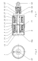
- Figure 1 is a sectional view through an embodiment an electromagnetic actuator shown.
- the control device shown in sectional view has a tubular housing 1. Inside the case 1, a control shaft 15 is arranged centrally by two Plain bearings 19a, 19b is guided and with a still to be explained Compensating element 51 cooperates.
- the staff 15 extends through the entire axial length of the housing 1.
- a plate-shaped Anchor 17 attached to the stem 15.
- the anchor 17 is located between two magnet systems and thus in the magnetic Circle of both the left and right magnet systems arranged. Both magnetic systems are after Kind of pot magnets preferably rotationally symmetrical.
- the magnet system arranged on the left in FIG. 1 exists from a pot-shaped jacket 9, a core 5 and a coil former 7, on which an excitation coil 3 is wound.
- Between the bottom plate of the jacket 9 and the core 5 is a plate-shaped permanent magnet 71 arranged.
- the magnetization this permanent magnet 71 is chosen so that the north pole N and south pole S are provided as plate-shaped elements are, the plate levels parallel to the plane of the plate-shaped Permanent magnets 71 are arranged.
- the separation of The north pole N and south pole S are dashed in Figure 1 in the permanent magnet 71 indicated.
- the permanent magnet 71 also has a central opening in which an annular element 13 sits. At this Element 13 is supported by a compression spring 11 with one end. This compression spring 11 is arranged coaxially around the control shaft 15. Around this compression spring 11 is the core 5 of the Magnet system. The compression spring 11 is supported with her other End at the plate-shaped anchor 17.
- This electromagnet has one a coil carrier 27 wound excitation coil 23.
- the Magnetic system of this electromagnet is in this embodiment also designed rotationally symmetrical and has a one-piece magnetic body 25, which has a central through opening. Through this Through opening extends the stem 15.
- the Position shaft 15 is guided in the bearing bush 19b, which on the Bottom side of the magnetic body 25 is attached.
- Compression spring 21 which is on the one hand on the plate-shaped armature 17th and on the other hand on a ring-shaped projecting shoulder supports in the vicinity of the bearing bush 19b.
- the left front this electromagnet is spaced from the opposite one Surface of the plate-shaped anchor 17.
- the end of the actuator stem protruding from the bearing bush 19b 15 is connected to a compensating element 51.
- This Compensating element 51 serves to ensure that even at existing end stop of the part to be moved the anchor plate 17 air gap on the magnetic body 25 of the electromagnet is applied. This measure guarantees a low holding power.
- the prestressed compression spring 53 in End of stroke position almost constant forces. So that to be moved Part that is articulated in the bore 52, too can perform an arcuate movement is the compensating element 51 on the control shaft 15 via a compensating ring 59 gimbal mounted.
- Such actuators are ideal where Large actuating forces in the stroke start or stroke end position with a small one Construction volume, small weight and small performance required e.g. for flap adjustments in automotive applications. Of this actuator is also suitable for actuation of elements that require a specific work profile.
- the two excitation coils 3, 23 are either connected in series or parallel to each other.
- the row or Parallel connection of the two excitation coils 3, 23 is with output terminals 43, 44 of the control circuit 41 already mentioned in connection.
- the entire actuator In the position of the armature 17 shown the entire actuator is in a de-energized state. In this de-energized state, the in the left magnet system ensures existing permanent magnet 71 for the armature 17 lies flat against the magnetic body 5, 9 of the left magnet system.
- the main advantage of this control device is that very simple control option by switching on and off a control signal. A separate control of the two excitation coils 3, 23 is no longer necessary.
- FIG. 3 shows two different block diagrams, in which the one in connection with FIG explained two excitation coils 3, 23 one after the other (cf. Figure 3 above) and on the other hand connected in parallel are (see FIG. 3 below). These two connected in series or excitation coils 3, 23 connected in parallel with output terminals 43, 44 of a control circuit 41 in connection.
- This control circuit 41 is shown schematically and contains only one switching device between two Switching states S1, S2 is switchable. In the switch position S1 reaches the control circuit 41 on the input side applied voltage U to the output terminals 43, 44 while with switch position S2 the switch is open and consequently at the output terminals 43, 44 of the control circuit 41 there is no voltage signal. From the illustration in FIG.
Abstract
Description
Die Erfindung betrifft eine elektromagnetisch arbeitende Stelleneinrichtung
der im Oberbegriff des Anspruchs 1 angegebenen
Art. Eine solche elektromagnetisch arbeitende Stelleinrichtung
ist aus DE-C-0 912 721 bekannt.The invention relates to an electromagnetically operating point device
the specified in the preamble of
Eine weitere elektromagnetisch arbeitende Stelleinrichtung ist
aus Patent Abstracts of Japan: vol 11, No. 140, (M-586) JP-A61278673
bekannt. Dort ist eine Steuerschaltung beschrieben
mit in Reihe oder parallel zueinander geschaltenen Erregerspulen,
wobei der Strom durch die Erregerspulen nach einem folgenden
ersten Wert auf einen niedrigeren zweiten Wert geschaltet
wird. Problematisch bei dieser Stelleinrichtung ist
die Vielzahl der notwendigen Schaltungskomponenten und die
komplizierte Ansteuerung dieser Schaltungskomponenten. So sind
unter anderem 2 Schalttransistoren in der Schaltungsanordnung
notwendig, die wechselseitig von der Steuerschaltung ein- ausgeschaltet
werden müssen.Another electromagnetic actuator is
from Patent Abstracts of Japan:
Weitere elektromagnetisch arbeitende Stelleinrichtungen sind aus EP-A-0 405 191 und EP-A-0 405 187 bekannt.Other electromagnetic actuators are known from EP-A-0 405 191 and EP-A-0 405 187.
Eine andere elektromagnetisch arbeitende Stelleinrichtung ist in DE 39 28 066 A1 beschrieben. Die Stelleinrichtung ist zur elektromagnetischen Steuerung des Gaswechsel-Ventils einer Hubkolben-Brennkraftmaschine vorgesehen. Die Stelleinrichtung weist zwei zueinander beanstandete Magnetsysteme auf, zwischen denen eine Ankerplatte mit einem Stellschaft, an den der Ventilteller des Ventils gekoppelt ist, hin- und herbewegbar ist. Das ventilseitige Magnetsystem zum Öffnen des Ventils besteht aus einem, an sich bekannten Elektromagneten mit Erregerspule, während das dem Ventil abgewandte Magnetsystem zum Schließen des Ventils einen Permanentmagneten aufweist, dessen Magnetfeld durch eine Kompensationsspule neutralisierbar ist.Another electromagnetic actuating device is described in DE 39 28 066 A1. The actuator is for electromagnetic control of the gas exchange valve one Reciprocating internal combustion engine provided. The actuator has two mutually objectionable magnet systems, between which an anchor plate with an actuator stem to which the valve plate of the valve is coupled, can be moved back and forth. The valve-side magnet system for opening the valve exists from a known electromagnet with excitation coil, while the magnetic system facing away from the valve for closing of the valve has a permanent magnet whose magnetic field can be neutralized by a compensation coil.
Eine weitere elektromagnetisch arbeitende Stelleinrichtung ist zum Beispiel in DE 35 00 530 A1 beschrieben. Zur Steuerung eines Ventils einer Verbrennungskraftmaschine ist anstelle der mechanischen Nockensteuerung eine elektromagnetisch arbeitende Steuerung vorgeschlagen. Diese besteht aus zwei Magnetsystemen mit jeweils einer Erregerspule und einem zugeordneten Dauermagneten. Beide Systeme, d.h. Permanent-Elektromagnete, wirken auf eine gemeinsame, zwischen ihnen gelegene Ankerplatte, welche mit einem Ventilschaft fest verbunden ist. Auf die Ankerplatte und damit das Ventil drücken in entgegengesetzter Richtung zwei Federn. Die Dauermagnete halten den Anker jeweils in den Endlagen. Die Haltekraft der Dauermagnete wird zur Auslösung der Ventilbewegung durch Erregung des zugeordneten elektromagnetischen Systems aufgehoben, so dass der Anker und damit das Ventil unter der Wirkung der jeweils anderen Magneten in die andere Endlage überführt wird.Another electromagnetic actuator is described for example in DE 35 00 530 A1. To control a Valve of an internal combustion engine is instead of that mechanical cam control an electromagnetically working Control suggested. This consists of two magnet systems each with an excitation coil and an associated permanent magnet. Both systems, i.e. Permanent electromagnets act on a common anchor plate between them, which is firmly connected to a valve stem. On the anchor plate and thus push the valve in the opposite direction two feathers. The permanent magnets keep the armature in the end positions. The holding force of the permanent magnets becomes a trigger the valve movement by energizing the associated electromagnetic System lifted so that the anchor and therefore the valve under the action of the other magnet is transferred to the other end position.
Die Haltekraft der beiden Dauermagnete läßt sich jeweils durch ein, dem Magnetfeld des Dauermagneten entgegengerichtetes Gleichfeld des zugehörenden Elektromagneten aufheben. Wird die Erregerspule des betreffenden Permanent-Elektromagneten also mit einem Strom geeigneter Polarität und Stärke bestromt, ist der Dauermagnet "neutralisiert". Die Folge ist, dass der Anker unter der Wirkung der vorgespannten Feder abfällt und von dem anderen Permanent-Elektromagneten eingefangen wird. Dessen Dauermagnet wiederum hält den Anker in seiner Hubendlage, bis seine Haltekraft durch das Gleichfeld des diesem Dauermagneten zugeordnet Dauermagneten zugeordneten elektromagnetischen Systems aufgehoben wird. Vorteilhaft bei dieser Lösung ist, dass jeweils nur ein kurzes abwechselndes Bestromen der elektromagnetischen Systeme notwendig ist. Ein weiterer Vorteil besteht darin, dass mit dieser Stelleinrichtung verhältnismäßig kurze Ventilschließ- und Öffnungszeiten erreichbar sind. Darüber hinaus sorgen die Dauermagnete dafür, dass das Steuerventil im Normalfall bei abgeschaltetem Motor und damit abgeschalteter Stromversorgung in der gewünschten Hubendlage bleibt.The holding force of the two permanent magnets can be determined by a, the magnetic field of the permanent magnet opposite Cancel the DC field of the associated electromagnet. Will the Excitation coil of the permanent electromagnet in question is supplied with a current of suitable polarity and strength the permanent magnet "neutralizes". The result is that the anchor falls under the action of the preloaded spring and from which other permanent electromagnet is captured. Whose Permanent magnet in turn holds the armature in its stroke end position until its holding force through the constant field of this permanent magnet assigned permanent magnets assigned electromagnetic system will be annulled. The advantage of this solution is that only a short alternating energization of the electromagnetic Systems is necessary. Another advantage is there in the fact that this control device is relatively short Valve closing and opening times are available. About that In addition, the permanent magnets ensure that the control valve in the Normally with the engine switched off and thus with the engine switched off Power supply remains in the desired stroke end position.
Um die geforderten kurzen Stellzeiten zu erhalten ist jedoch eine verhältnismäßig komplizierte Beaufschlagung der beiden Erregerspulen mit geeigneten Steuersignalen erforderlich. Um einen ordnungsgemäßen Betrieb der Stelleinrichtung zu gewährleisten, muß eine Steuerschaltung den beiden Erregerspulen jeweils separat geeignete Steuersignale zur Verfügung stellen. Hierbei muß die Steuerschaltung zwingend sicherstellen, dass kein zeitliches Überlappen der Einschaltzeiten versehentlich auftritt. Darüber hinaus müssen die Ein- und Ausschaltzeiten der Steuersignale für die beiden Erregerspulen zeitlich exakt aufeinander abgestimmt werden.However, in order to obtain the short operating times required a relatively complicated act on the two Excitation coils with suitable control signals required. Around to ensure proper operation of the actuating device, must a control circuit each of the two excitation coils Provide suitable control signals separately. The control circuit must ensure that no overlapping of the switch-on times accidentally occurs. In addition, the on and off times of the control signals for the two excitation coils exactly in time be coordinated.
Ähnliche Stelleinrichtungen sind auch in DE 30 24 109 A1 und DE 33 07 683 C1 beschrieben. Beide Stelleinrichtungen weisen ebenfalls zwei Elektromagneten auf, zwischen denen eine Ankerplatte hin- und her bewegbar ist. Die Ankerplatte selbst ist mit einem Stellschaft feststehend verbunden. In diesen beiden Dokumenten ist jedoch kein Magnetsystem mit Dauermagneten vorgesehen.Similar actuators are also in DE 30 24 109 A1 and DE 33 07 683 C1 described. Both actuators have also two electromagnets, between which an anchor plate is movable back and forth. The anchor plate itself is firmly connected with an employment. In these two However, no magnetic system with permanent magnets is provided for documents.
Sämtlichen o.b. Stelleinrichtungen ist gemeinsam, dass die zwei vorgesehenen Magnetsysteme zur Erzielung kurzer Schaltzeiten separat mit entsprechend geeigneten Steuersignalen angesteuert werden müssen, was einen erheblichen schaltungstechnischen Aufwand in einer Steuerschaltung verursacht, und dass die Ankerplatte bei abgeschalteter Stromversorgung oder bei einem Ansteuerungsfehler eine regelmäßig unerwünschte Mittelstellung einnimmt. Dies bedeutet, dass für einen Neustart eine zusätzliche Einrichtung, ähnlich wie in DE 30 24 109 A1 oder DE 33 07 683 C1 beschrieben, erforderlich ist, um die Ankerplatte aus der unerwünschten Mittellage herauszuholen.All o.b. The common feature is that the two provided magnet systems to achieve short switching times controlled separately with appropriate control signals have to be what a significant circuit Effort in a control circuit causes, and that the anchor plate when the power supply is switched off or at a control error a regularly undesirable middle position occupies. This means that for a restart a additional device, similar to DE 30 24 109 A1 or DE 33 07 683 C1 described, is required to the anchor plate to get out of the unwanted middle position.
Bei den o.b. Stelleinrichtungen ist aufgrund der notwendigen separaten Ansteuerung der in den beiden Magnetsystemen vorhandenen Erreger- bzw. Kompensationsspulen zwingend erforderlich, dass jede dieser Spulen mit getrennten Ausgängen einer geeigneten Steuerschaltung in Verbindung steht. Eine Parallel- oder Reihenschaltung dieser Spulen ist damit ausgeschlossen.At the o.b. Adjustment devices is necessary due to the separate control of the existing in the two magnet systems Excitation or compensation coils absolutely necessary, that each of these coils with separate outputs of a suitable one Control circuit is connected. A parallel or Series connection of these coils is therefore excluded.
Der vorliegenden Erfindung liegt die Aufgabe zugrunde, die eingangs genannte elektromagnetisch arbeitende Stelleinrichtung so weiterzubilden, dass einerseits eine erheblich einfachere Ansteuerung der Erregerspulen möglich ist, und andererseits die Stelleinrichtung im unbestromten Zustand stets in eine definierte, vorgegebene Endlage gebracht wird.The present invention is based on the object Electromechanical actuator mentioned at the beginning so that on the one hand a considerably easier one Control of the excitation coils is possible, and on the other hand the actuator in the de-energized state always in a defined, predetermined end position is brought.
Diese Aufgabe wird bei der eingangs genannten elektromagnetisch arbeitenden Stelleinrichtung durch die im Kennzeichen des Anspruchs 1 angegebenen Merkmale gelöst.This task is electromagnetic in the aforementioned Actuating device working in the license plate of the specified features solved.
Die Erfindung besteht also im wesentlichen darin, dass den beiden unverändert in Reihe oder parallel zueinander geschalteten Erregerspulen von der Steuerschaltung zum wechselseitigen Bewegen des Ankers in die erste und die zweite Schaltposition Ein-/Aus-Steuersignale bereitgestellt werden, wobei das Ein-Steuersignal nach einem vorgegebenen ersten Wert auf einen niedrigeren zweiten Wert ( Halteerregung) absenkbar ist.The invention therefore essentially consists in that both connected in series or parallel to each other unchanged Excitation coils from the control circuit to the mutual Moving the armature into the first and second switching positions On / off control signals are provided, the A control signal after a predetermined first value lower second value (holding excitation) can be reduced.
Im Gegensatz zu den bekannten elektromagnetisch arbeitenden Stelleinrichtungen ist bei der Stelleinrichtung nach der Erfindung immer sichergestellt, dass der Anker in unbestromten Zustand der Erregerspulen eine stabile Endlage einnimmt. Sobald die Steuerschaltung ein Steuersignal zum Bestromen der Erregerspulen bereitstellt, werden beide Erregerspulen aufgrund ihrer Serien- oder Parallelschaltung von Strom durchflossen. Bei ausreichender Stromstärke und richtiger Polarität des Stromes wird der Anker ausgehend von seiner Ruhestellung, bei welchem er an dem mit dem Permanentmagneten versehenen Elektromagneten anliegt, an den gegenüberliegenden Elektromagneten gezogen. Dies geschieht deshalb, weil die Wirkung des Permanentmagneten einerseits durch die Bestromung der einen Erregerspule neutralisiert und sich durch die gleichzeitige Erregung der anderen Erregerspule ein Magnetfeld im anderen Elektromagneten aufbaut. Dieses letztgenannte Magnetfeld zieht den Anker an den anderen Elektromagneten an. Wird anschließend der Strom durch die beiden Erregerspulen abgeschaltet, fällt der Anker wieder in seine Ruhestellung zurück.In contrast to the known electromagnetic working Actuators is in the actuator according to the invention always ensure that the anchor is in de-energized Condition of the excitation coils assumes a stable end position. As soon as the control circuit a control signal for energizing the Provides excitation coils, both excitation coils are due through their series or parallel connection of current. With sufficient current and correct polarity of the current the anchor is based on its rest position, in which he on the one provided with the permanent magnet Electromagnet is present on the opposite electromagnet drawn. This happens because the effect of the Permanent magnets on the one hand by energizing one Excitation coil neutralized and by the simultaneous Excitation of the other excitation coil one magnetic field in the other Electromagnet builds up. This latter magnetic field pulls the armature to the other electromagnet. Will then the current through the two excitation coils switched off, falls the anchor returns to its rest position.
Vorzugsweise werden die Federkräfte der Federn und die Magnetkraft des Dauermagneten so dimensioniert, dass der Anker im unbestromten Zustand der beiden Erregerspulen aus der allein durch die Federn vorgegebenen stabilen Federlage in Richtung desjenigen Magnetsystemes, dem der Dauermagnet zugeordnet ist, versetzt sitzt.The spring force of the springs and the magnetic force are preferred of the permanent magnet dimensioned so that the armature in de-energized state of the two excitation coils from the alone given by the springs stable spring position in the direction of the magnet system to which the permanent magnet is assigned, staggered.
Der wesentliche Vorteil der erfindungsgemäßen Stelleinrichtung liegt darin, dass beide Erregerspulen von ein und denselben Steuersignalen einer Steuerschaltung beaufschlagt werden können, da dass eine sehr einfach aufgebaute Steuerschaltung ausreicht. Die Steuerschaltung kann beispielsweise an ihren Ausgangsklemmen ein pulsweitenmoduliertes Spannungssignal zur Verfügung stellen, mit dessen Einschaltdauer die Stromstärke bestimmt werden kann.The main advantage of the actuating device according to the invention is that both excitation coils are from one and the same Control signals of a control circuit can be applied, because that a very simple control circuit is sufficient. The control circuit can, for example, at its output terminals a pulse width modulated voltage signal for Provide the current with its duty cycle can be determined.
Um große Schaltkräfte der Stelleinrichtung nach der Erfindung zu erzielen, werden in einer Weiterbildung der Erfindung die beiden Magnetsysteme vorzugsweise mit einem Überregungsstrom geschaltet (100% DE). Dieser Übererregungsstrom neutralisiert den Permanentmagneten und verleiht dem anderen Magnetsystem große Schaltkräfte. Nach erfolgtem Schaltvorgang mit Übererregungsstrom wird auf einen geringeren Stromwert, den sogenannten Haltestrom, zurückgeregelt bzw. zurückgeschaltet (geringere % ED, geringere Leistungsaufnahmen, geringere Erwärmung). Der Haltestrom wird erfindungsgemäß so dimensioniert, dass die gewünschte Haltekraft bei einem Luftspalt Null zwischen Permanentmagnet und Magnetsystem sichergestellt ist.To large switching forces of the actuating device according to the invention to achieve, in a further development of the invention both magnet systems preferably with an overexcitation current switched (100% DE). This overexcitation current neutralizes the permanent magnet and gives the other magnet system large switching forces. After switching operation with overexcitation current is reduced to a lower current value, the so-called Holding current, reduced or switched back (lower % ED, lower power consumption, less warming). The holding current is dimensioned according to the invention so that the Desired holding force with zero air gap between permanent magnet and magnet system is ensured.
Die Stelleinrichtung nach der Erfindung wird nachfolgend anhand eines Ausführungsbeispieles im Zusammenhang mit Figuren näher erläutert. Es zeigen:
Figur 1- eine Schnittansicht durch ein erstes Ausführungsbeispiel einer elektromechanisch arbeitenden Stelleinrichtung nach der Erfindung,
Figur 2- eine stirnseitige Draufsicht auf die Stelleinrichtung
von
Figur 1, Figur 3- zwei mögliche Blockschaltbilder mit einer an eine
Steuereinrichtung geschalteten Stelleinrichtung gemäß
Figur 1
- Figure 1
- 2 shows a sectional view through a first exemplary embodiment of an electromechanically operating actuating device according to the invention,
- Figure 2
- 3 shows an end view of the actuating device from FIG. 1,
- Figure 3
- two possible block diagrams with an actuating device connected to a control device according to FIG. 1
In den nachfolgenden Figuren bezeichnen, sofern nicht anders angegeben, gleiche Bezugszeichen gleiche Teile mit gleicher Bedeutung.Designate in the following figures, unless otherwise indicated, same reference numerals, same parts with the same Importance.
In Figur 1 ist eine Schnittansicht durch ein Ausführungsbeispiel
einer elektromagnetisch arbeitenden Stelleinrichtung
dargestellt. Die in Schnittansicht gezeigte Stelleinrichtung
weist ein rohrförmiges Gehäuse 1 auf. Innerhalb des Gehäuses
1 ist zentrisch ein Stellschaft 15 angeordnet, der durch zwei
Gleitlager 19a, 19b geführt wird und mit einem noch zu erläuternden
Ausgleichselement 51 zusammenwirkt. Der Stellschaft 15
erstreckt sich durch die gesamte axiale Länge des Gehäuses 1.In Figure 1 is a sectional view through an embodiment
an electromagnetic actuator
shown. The control device shown in sectional view
has a
Auf etwa halber axialer Länge des Gehäuses 1 ist ein plattenförmiger
Anker 17 an dem Stellschaft 15 befestigt. Der Anker
17 ist zwischen zwei Magnetsystemen gelegen und damit im magnetischen
Kreis sowohl des linken als auch des rechten Magnetsystems
angeordnet. Beide magnetische Systeme sind nach
Art von Topfmagneten vorzugsweise rotationssymmetrisch ausgebildet.
Das in Figur 1 links angeordnete Magnetsystem besteht
aus einem topfförmigen Mantel 9, einen Kern 5 und einen Spulenträger
7, auf welchen eine Erregerspule 3 gewickelt ist.
Zwischen der Bodenplatte des Mantels 9 und dem Kern 5 ist ein
plattenförmiger Permanentmagnet 71 angeordnet. Die Magnetisierung
dieses Permanentmagneten 71 ist so gewählt, daß der Nordpol
N und Südpol S als plattenförmige Elemente vorgesehen
sind, deren Plattenebenen parallel zur Ebene des plattenförmigen
Permanentmagneten 71 angeordnet sind. Die Trennung von
Nordpol N und Südpol S ist in Figur 1 strichliniert im Permanentmagneten
71 angedeutet.At about half the axial length of the
In der Bodenplatte des Mantels 9 ist eine Öffnung vorhanden,
in welcher eine Lagerbuchse 19a sitzt. In dieser Lagerbuchse
19a und in einer gegenüberliegenden Lagerbuchse 19b wird der
Stellschaft 15 geführt.There is an opening in the bottom plate of the
Der Permanentmagnet 71 weist ebenfalls eine mittige Öffnung
auf, in welcher ein ringförmiges Element 13 sitzt. An diesem
Element 13 stützt sich eine Druckfeder 11 mit einem Ende ab.
Diese Druckfeder 11 ist koaxial um den Stellschaft 15 angeordnet.
Um diese Druckfeder 11 herum befindet sich der Kern 5 des
Magnetsystems. Die Druckfeder 11 stützt sich mit ihrem anderen
Ende am plattenförmigen Anker 17 ab.The
Wie die Darstellung von Figur 1 zeigt, liegt der plattenförmige
Anker 17 flächig an der Stirnseite des linken Magnetsystems
luftspaltfrei an.As the representation of Figure 1 shows, the plate-shaped
Innerhalb des Gehäuses 1 ist ein weiteres Magnetsystem, das
nur einen Elektromagneten und keinen zugeordneten Dauermagnet
aufweist, angeordnet. Dieser Elektromagnet weist eine auf
einen Spulenträger 27 aufgewickelte Erregerspule 23 auf. Das
Magnetsystem dieses Elektromageneten ist in diesem Ausführungsbeispiel
ebenfalls rotationssymmetrisch gestaltet und
verfügt über einen einstückig ausgeführten Magnetkörper 25,
welcher eine mittige Durchgangsöffnung aufweist. Durch diese
Durchgangsöffnung erstreckt sich der Stellschaft 15. Der
Stellschaft 15 ist in der Lagerbuchse 19b geführt, die an der
Bodenseite des Magnetkörpers 25 befestigt ist. In der zentrischen
Durchgangsöffnung des Magnetkörpers 25 sitzt eine
Druckfeder 21, die sich einerseits am plattenförmigen Anker 17
und andererseits an einer ringförmig hervorspringenden Schulter
in der Nähe der Lagerbuchse 19b abstützt. Die linke Stirnseite
dieses Elektromagneten ist beabstandet zur gegenüberliegenden
Oberfläche des plattenförmigen Ankers 17.Within the
Das aus der Lagerbuchse 19b herausragende Ende des Stellschaftes
15 ist mit einem Ausgleichselement 51 verbunden. Dieses
Ausgleichselement 51 dient dazu, sicherzustellen, daß auch bei
vorhandenem Endanschlag des zu bewegenden Teiles die Ankerplatte
17 luftspaltlos am Magnetkörper 25 des Elektromagneten
anliegt. Diese Maßnahme garantiert eine geringe Halteleistung.
Des weiteren garantiert die vorgespannte Druckfeder 53 in
Hubendstellung annähernd konstante Kräfte. Damit das zu bewegende
Teil, welches in der Bohrung 52 angelenkt wird, auch
eine bogenförmige Bewegung ausführen kann, ist das Ausgleichselement
51 auf dem Stellschaft 15 über einen Ausgleichsring
59 kardanisch gelagert.The end of the actuator stem protruding from the bearing
Derartige Stelleinheiten bieten sich vorzugsweise dort an, wo große Stellkräfte in Hubanfangs- bzw. Hubendlage bei kleinem Bauvolumen, kleinem Gewicht und kleiner Leistung benötigt werden, z.B. bei Klappenverstellungen in Kfz-Anwendungen. Des weiteren eignet sich diese Stelleinheit auch zur Betätigung von Elementen, die ein bestimmten Hubarbeitsprofil benötigen.Such actuators are ideal where Large actuating forces in the stroke start or stroke end position with a small one Construction volume, small weight and small performance required e.g. for flap adjustments in automotive applications. Of this actuator is also suitable for actuation of elements that require a specific work profile.
Die beiden Erregerspulen 3, 23 sind erfindungsgemäß entweder
in Reihe oder parallel zueinander geschaltet. Die Reihen- oder
Parallelschaltung der beiden Erregerspulen 3, 23 ist mit Ausgangsklemmen
43, 44 der bereits erwähnten Steuerschaltung 41
in Verbindung. In der dargestellten Stellung des Ankers 17
befindet sich die gesamte Stelleinrichtung im stromlosen Zustand.
In diesem stromlosen Zustand sorgt der im linken Magnetsystem
vorhandene Permanentmagnet 71 dafür, daß der Anker
17 flächig am Magnetkörper 5, 9 des linken Magnetsystems anliegt.According to the invention, the two
Stellt die Steuerschaltung 41 an ihren Ausgangsklemmen 43, 44
einen Strom geeigneter Polarität in ausreichender Höhe zur
Verfügung, baut sich in dem linken Magnetsystem ein Magnetfeld
auf, das die Magnetwirkung des Permanentmagneten 71 aufhebt.
Zugleich baut sich durch die Bestromung der Erregerspule 23 im
rechten Elektromagneten ein Magnetfeld auf, das den Anker 17
anzieht. Der Anker 17 bewegt sich daher zum rechten Elektromagneten
und schlägt dort an der linken Stirnseite des Magnetkörpers
25 an. Wird die Bestromung der beiden Erregerspulen 3,
23 beendet, fällt der Anker 17 wieder zurück in die in Figur
1 dargestellte Stellung.Provides the
Der wesentliche Vorteil dieser Stelleinrichtung besteht in der
sehr einfachen Ansteuerungsmöglichkeit durch Ein- und Ausschalten
eines Steuersignales. Eine separate Ansteuerung der
beiden Erregerspulen 3, 23 ist nicht mehr notwendig. The main advantage of this control device is that
very simple control option by switching on and off
a control signal. A separate control of the
two
In Figur 3 sind zwei verschiedene Blockschaltbilder dargestellt,
bei denen einmal die im Zusammenhang mit Figur 1
erläuterten beiden Erregerspulen 3, 23 hintereinander (vgl.
Figur 3 oben) und zum anderen parallel zueinander geschaltet
sind (vgl. Figur 3 unten). Diese beiden hintereinander geschalteten
oder parallel geschalteten Erregerspulen 3, 23 sind
mit Ausgangsklemmen 43, 44 einer Steuerschaltung 41 in Verbindung.
Diese Steuerschaltung 41 ist schematisch dargestellt und
enthält lediglich eine Schalteinrichtung, die zwischen zwei
Schaltzuständen S1, S2 umschaltbar ist. In der Schalterstellung
S1 gelangt eine eingangsseitig an die Steuerschaltung 41
angelegte Spannung U an die Ausgangsklemmen 43, 44, während
bei der Schalterstellung S2 der Schalter offen ist und demzufolge
an den Ausgangsklemmen 43, 44 der Steuerschaltung 41
kein Spannungssignal ansteht. Aus der Darstellung von Figur 3
ist klar ersichtlich, daß in der Schalterstellung S1 unabhängig
von der Wahl einer Serien- oder Parallelschaltung der
Erregerspulen 3, 23 diese gleichzeitig von Strom durchflossen
werden. Eine separate Ansteuerung beider Erregerspulen 3, 23
ist nicht erforderlich. Der Vollständigkeit halber sind in
Figur 3 die beiden mit den Ausgangsklemmen 43, 44 verbundenen
Zuleitungen mit den Bezugszeichen 31, 32 versehen. 3 shows two different block diagrams,
in which the one in connection with FIG
explained two
- 11
- Gehäusecasing
- 33
- Erregerspuleexcitation coil
- 55
- Kerncore
- 77
- Spulenträgercoil carrier
- 99
- Metallteilmetal part
- 1111
- Druckfedercompression spring
- 1515
- Stellschaftset shaft
- 1717
- Ankeranchor
- 19a19a
- Gleitlagerbearings
- 19b19b
- Gleitlagerbearings
- 2121
- Druckfedercompression spring
- 2323
- Erregerspuleexcitation coil
- 2525
- Kerncore
- 2727
- Spulenträgercoil carrier
- 3131
- Leitungmanagement
- 3232
- Leitungmanagement
- 4141
- Steuerschaltungcontrol circuit
- 4343
- Ausgangsklemmenoutput terminals
- 4444
- Ausgangsklemmenoutput terminals
- 5151
- Ausgleichselementcompensation element
- 5252
- Bohrungdrilling
- 5353
- Druckfedercompression spring
- 5959
- Ausgleichsringcompensation ring
- 7171
- Permanentmagnetpermanent magnet
Claims (12)
- Electromagnetically operating positioning device with two magnet systems spaced apart from one another and each having an excitation coil (3, 23), between which is arranged an armature (17), which is positively connected to a positioning shaft (15), is clamped between two springs (11, 21) acting in opposition and is movable by the magnet systems into two switching positions, a permanent magnet (71) being associated with just one of the two magnet systems and the two excitation coils (3, 23) being connected either in series or in parallel with one another, and it being possible for them to be connected to output terminals (43, 44) of a control circuit (41), characterised in that on/off control signals (S1, S2) are provided from the control circuit (41) to the two unchanged excitation coils (3, 23) connected in series or parallel with one another for the reciprocal movement of the armature (17) into the first and the second switching position, it being possible to reduce the on control signal (S1) after a given first value (over-excitation) to a lower second value (holding excitation).
- Electromagnetically operating positioning device according to Claim 1, characterised in that the springs (11, 21) and the permanent magnet (71) are sized so that, in the de-energised state of the two excitation coils (3, 23), the armature (17) are [sic] offset from the stable spring position defined by the springs (11, 21) alone in the direction of that magnet system, with which the permanent magnet (17) is associated.
- Electromagnetically operating positioning device according to Claim 1 or 2, characterised in that an on signal S1 can be controlled by a pulse width modulation.
- Electromagnetically operating positioning device according to one of Claims 1 to 3, characterised in that the amplitude and polarity of the on control signals (S1) is chosen so that the holding effect of the permanent magnet (71) is just neutralised in the first electromagnet.
- Electromagnetically operating positioning device according to one of Claims 1 to 4, characterised in that an on control signal (S1) can be made available by the control circuit (41), which, after a given first value (over-excitation) is reduced to a lower second value (holding excitation).
- Electromagnetically operating positioning device according to one of Claims 1 to 5, characterised in that the armature (17) is designed in the form of a plate.
- Electromagnetically operating positioning device according to one of Claims 1 to 6, characterised in that the two excitation coils (3, 23) are designed identically to one another.
- Electromagnetically operating positioning device according to one of Claims 1 to 7, characterised in that the two excitation coils (3, 23) are designed differently.
- Electromagnetically operating positioning device according to one of Claims 1 to 8, characterised in that the permanent magnet (71) lies parallel to the armature (17) but flat against the side of the first electromagnet, which faces away from the armature (17).
- Electromagnetically operating positioning device according to one of Claims 1 to 9, characterised in that both poles (N, S) of the permanent magnet (71) are plate-shaped and arranged next to one another and parallel to the plane of the plate of the permanent magnet (71).
- Electromagnetically operating positioning device according to one of Claims 1 to 10, characterised in that the positioning device is coupled to a part to be moved via a compensation element (51) and in that the compensation element (51) enables the armature (17) to lie against the core (25) of the magnet system without an air gap when an end stop exists for the part to be moved.
- Electromagnetically operating positioning device according to one of Claims 1 to 11, characterised in that the compensation element (51) provides for an axial stroke compensation, an arc-shaped stroke compensation for rotary movement via an eccentric or a rotational stroke compensation after converting an axial movement into a rotary movement.
Applications Claiming Priority (2)
| Application Number | Priority Date | Filing Date | Title |
|---|---|---|---|
| DE19712293 | 1997-03-24 | ||
| DE19712293A DE19712293A1 (en) | 1997-03-24 | 1997-03-24 | Electromagnetic actuator |
Publications (2)
| Publication Number | Publication Date |
|---|---|
| EP0867898A1 EP0867898A1 (en) | 1998-09-30 |
| EP0867898B1 true EP0867898B1 (en) | 2002-11-27 |
Family
ID=7824429
Family Applications (1)
| Application Number | Title | Priority Date | Filing Date |
|---|---|---|---|
| EP98100775A Expired - Lifetime EP0867898B1 (en) | 1997-03-24 | 1998-01-17 | Electromagnetic positioning device |
Country Status (5)
| Country | Link |
|---|---|
| EP (1) | EP0867898B1 (en) |
| AT (1) | ATE228712T1 (en) |
| DE (2) | DE19712293A1 (en) |
| ES (1) | ES2186928T3 (en) |
| PT (1) | PT867898E (en) |
Cited By (1)
| Publication number | Priority date | Publication date | Assignee | Title |
|---|---|---|---|---|
| DE102005039263A1 (en) * | 2005-08-19 | 2007-02-22 | Deere & Company, Moline | Control device and method for driving an actuator for a transmission shift point |
Families Citing this family (12)
| Publication number | Priority date | Publication date | Assignee | Title |
|---|---|---|---|---|
| JP3835024B2 (en) * | 1998-11-19 | 2006-10-18 | トヨタ自動車株式会社 | Electromagnetic drive device for internal combustion engine |
| DE10207828B4 (en) * | 2002-02-25 | 2004-10-07 | Technische Universität Dresden | Electromagnetic solenoid |
| DE10322881A1 (en) * | 2003-05-21 | 2004-12-16 | Bayerische Motoren Werke Ag | Electric valve train with electric and permanent magnets |
| DE102007044245A1 (en) * | 2007-09-11 | 2009-04-02 | Siemens Ag | Magnetic drive system for a switching device and method for producing a magnetic drive system |
| DE202009014192U1 (en) * | 2009-10-20 | 2011-03-03 | Eto Magnetic Gmbh | Monostable electromagnetic actuator device |
| EP2339681B1 (en) * | 2009-12-18 | 2013-09-18 | Bayerische Motoren Werke Aktiengesellschaft | Electromagnetic actuator |
| CN102266633B (en) * | 2010-12-31 | 2013-08-14 | 北京谊安医疗系统股份有限公司 | Electromagnetic proportional valve and breathing machine comprising same |
| DE102011106205A1 (en) | 2011-06-07 | 2012-12-13 | Hochschule Bochum | Bistable electric lifting magnet for use in e.g. valve, has movable armature that is fixed co-linear with respect to ferromagnetic core |
| DE102013102400B4 (en) | 2013-03-11 | 2021-08-26 | Alfred Jäger GmbH | Electromagnetic actuator and combination of electromagnetic actuator and motor spindle |
| DE102020109120B4 (en) | 2020-04-01 | 2022-02-03 | Alfred Jäger GmbH | Electromagnetic actuator and its use |
| WO2023241760A1 (en) | 2022-06-13 | 2023-12-21 | Alfred Jäger GmbH | Magnetic actuating device |
| DE102022114839A1 (en) | 2022-06-13 | 2023-12-14 | Alfred Jäger GmbH | Magnetic actuator |
Family Cites Families (5)
| Publication number | Priority date | Publication date | Assignee | Title |
|---|---|---|---|---|
| DE912721C (en) * | 1950-10-15 | 1954-06-03 | Siemens Ag | Device for jerking masses to and fro |
| DE3920978A1 (en) * | 1989-06-27 | 1991-01-10 | Fev Motorentech Gmbh & Co Kg | ELECTROMAGNETIC OPERATING DEVICE |
| DE3920931A1 (en) * | 1989-06-27 | 1991-01-03 | Fev Motorentech Gmbh & Co Kg | ELECTROMAGNETIC OPERATING DEVICE |
| DE3928066A1 (en) * | 1989-08-25 | 1991-02-28 | Binder Magnete | EM valve opening and closing device - has two magnet systems of small dimensions to reduce reaction time |
| DE4004876A1 (en) * | 1990-02-16 | 1991-09-26 | Ulrich Karrer | Electrically operated valve gear for IC engine - opens and closes valve by multiplication of stroke of hydraulic piston with alternate energisation of two electromagnets |
-
1997
- 1997-03-24 DE DE19712293A patent/DE19712293A1/en not_active Withdrawn
-
1998
- 1998-01-17 PT PT98100775T patent/PT867898E/en unknown
- 1998-01-17 DE DE59806390T patent/DE59806390D1/en not_active Expired - Lifetime
- 1998-01-17 EP EP98100775A patent/EP0867898B1/en not_active Expired - Lifetime
- 1998-01-17 AT AT98100775T patent/ATE228712T1/en active
- 1998-01-17 ES ES98100775T patent/ES2186928T3/en not_active Expired - Lifetime
Cited By (2)
| Publication number | Priority date | Publication date | Assignee | Title |
|---|---|---|---|---|
| DE102005039263A1 (en) * | 2005-08-19 | 2007-02-22 | Deere & Company, Moline | Control device and method for driving an actuator for a transmission shift point |
| DE102005039263B4 (en) * | 2005-08-19 | 2021-07-08 | Deere & Company | Control device and method for controlling an actuator for a gear shift point |
Also Published As
| Publication number | Publication date |
|---|---|
| DE19712293A1 (en) | 1998-10-01 |
| EP0867898A1 (en) | 1998-09-30 |
| DE59806390D1 (en) | 2003-01-09 |
| ES2186928T3 (en) | 2003-05-16 |
| PT867898E (en) | 2003-04-30 |
| ATE228712T1 (en) | 2002-12-15 |
Similar Documents
| Publication | Publication Date | Title |
|---|---|---|
| DE10131155B4 (en) | Electromagnetic actuator | |
| EP1262639B1 (en) | Electromagnetic actuator driving method, in particular for actuating valves in an internal combustion engine. | |
| DE19909305B4 (en) | Method for controlling an electromagnetic valve for actuating a motor valve | |
| EP0867898B1 (en) | Electromagnetic positioning device | |
| EP0118591A1 (en) | Process and device for activating an electromagnetic positioner | |
| EP0340625A1 (en) | Magnetic valve | |
| EP0197356A2 (en) | Electromagnetically operating adjustment system | |
| DE19751609B4 (en) | Narrow-building electromagnetic actuator | |
| DE10207828A1 (en) | Solenoid magnet has stator and excitation coil, with armature including permanent magnet polarized at right angles to direction of motion of armature | |
| DE2614004A1 (en) | ACTUATION DEVICE | |
| WO2001099129A1 (en) | Actuator, in particular for valves, relays or similar | |
| EP1069285B1 (en) | Electromagnetic actuating device for operating a gas exchange valve with stacking springs | |
| DE1550632A1 (en) | Electro-hydraulic valve | |
| DE102006025397B4 (en) | Electromagnetically driven valve | |
| DE4445069A1 (en) | Polarized relay | |
| EP0935054A2 (en) | Electromagnetic actuator | |
| DE602004007420T2 (en) | Electromagnetic actuator for actuating a gas exchange valve on a reciprocating internal combustion engine and internal combustion engine with such an actuator | |
| EP1417404A1 (en) | High-speed controlling device | |
| EP0793004B1 (en) | Electromagnetic valve control | |
| DE19712062A1 (en) | Electromagnetic control device | |
| DE102004037360B4 (en) | Electromagnetic actuator | |
| EP0132504B1 (en) | Device for controlling the idle speed of an internal-combustion engine | |
| DE19714410A1 (en) | Electromagnetic control device | |
| DE102018209397A1 (en) | Valve drive device with switching device | |
| DE19810609A1 (en) | Electromagnetic positioning device for actuating a valve in an internal combustion engine |
Legal Events
| Date | Code | Title | Description |
|---|---|---|---|
| PUAI | Public reference made under article 153(3) epc to a published international application that has entered the european phase |
Free format text: ORIGINAL CODE: 0009012 |
|
| AK | Designated contracting states |
Kind code of ref document: A1 Designated state(s): AT DE ES FR GB IT NL PT SE |
|
| AX | Request for extension of the european patent |
Free format text: AL;LT;LV;MK;RO;SI |
|
| 17P | Request for examination filed |
Effective date: 19981230 |
|
| 17Q | First examination report despatched |
Effective date: 19990219 |
|
| AKX | Designation fees paid |
Free format text: AT DE ES FR GB IT NL PT SE |
|
| RAP1 | Party data changed (applicant data changed or rights of an application transferred) |
Owner name: KENDRION BINDER MAGNETE GMBH |
|
| GRAG | Despatch of communication of intention to grant |
Free format text: ORIGINAL CODE: EPIDOS AGRA |
|
| GRAG | Despatch of communication of intention to grant |
Free format text: ORIGINAL CODE: EPIDOS AGRA |
|
| GRAH | Despatch of communication of intention to grant a patent |
Free format text: ORIGINAL CODE: EPIDOS IGRA |
|
| GRAH | Despatch of communication of intention to grant a patent |
Free format text: ORIGINAL CODE: EPIDOS IGRA |
|
| GRAA | (expected) grant |
Free format text: ORIGINAL CODE: 0009210 |
|
| AK | Designated contracting states |
Kind code of ref document: B1 Designated state(s): AT DE ES FR GB IT NL PT SE |
|
| REF | Corresponds to: |
Ref document number: 228712 Country of ref document: AT Date of ref document: 20021215 Kind code of ref document: T |
|
| REG | Reference to a national code |
Ref country code: GB Ref legal event code: FG4D Free format text: NOT ENGLISH |
|
| REF | Corresponds to: |
Ref document number: 59806390 Country of ref document: DE Date of ref document: 20030109 |
|
| GBT | Gb: translation of ep patent filed (gb section 77(6)(a)/1977) |
Effective date: 20030205 |
|
| REG | Reference to a national code |
Ref country code: PT Ref legal event code: SC4A Free format text: AVAILABILITY OF NATIONAL TRANSLATION Effective date: 20030225 |
|
| REG | Reference to a national code |
Ref country code: ES Ref legal event code: FG2A Ref document number: 2186928 Country of ref document: ES Kind code of ref document: T3 |
|
| ET | Fr: translation filed | ||
| PLBE | No opposition filed within time limit |
Free format text: ORIGINAL CODE: 0009261 |
|
| STAA | Information on the status of an ep patent application or granted ep patent |
Free format text: STATUS: NO OPPOSITION FILED WITHIN TIME LIMIT |
|
| 26N | No opposition filed |
Effective date: 20030828 |
|
| REG | Reference to a national code |
Ref country code: DE Ref legal event code: R082 Ref document number: 59806390 Country of ref document: DE Representative=s name: PATENTANWAELTE WESTPHAL MUSSGNUG & PARTNER, DE |
|
| REG | Reference to a national code |
Ref country code: DE Ref legal event code: R082 Ref document number: 59806390 Country of ref document: DE Representative=s name: WESTPHAL, MUSSGNUG & PARTNER PATENTANWAELTE MI, DE Effective date: 20120820 Ref country code: DE Ref legal event code: R082 Ref document number: 59806390 Country of ref document: DE Representative=s name: PATENTANWAELTE WESTPHAL MUSSGNUG & PARTNER, DE Effective date: 20120820 Ref country code: DE Ref legal event code: R081 Ref document number: 59806390 Country of ref document: DE Owner name: KENDRION (VILLINGEN) GMBH, DE Free format text: FORMER OWNER: KENDRION BINDER MAGNETE GMBH, 78048 VILLINGEN-SCHWENNINGEN, DE Effective date: 20120820 |
|
| REG | Reference to a national code |
Ref country code: NL Ref legal event code: TD Effective date: 20121115 |
|
| REG | Reference to a national code |
Ref country code: FR Ref legal event code: CD Owner name: KENDRION GMBH, DE Effective date: 20121114 Ref country code: FR Ref legal event code: CA Effective date: 20121114 |
|
| REG | Reference to a national code |
Ref country code: AT Ref legal event code: HC Ref document number: 228712 Country of ref document: AT Kind code of ref document: T Owner name: KENDRION (VILLINGEN) GMBH, DE Effective date: 20121128 |
|
| REG | Reference to a national code |
Ref country code: ES Ref legal event code: PC2A Owner name: KENDRION (VILLINGEN) GMBH Effective date: 20130205 |
|
| PGFP | Annual fee paid to national office [announced via postgrant information from national office to epo] |
Ref country code: NL Payment date: 20150122 Year of fee payment: 18 |
|
| PGFP | Annual fee paid to national office [announced via postgrant information from national office to epo] |
Ref country code: PT Payment date: 20150108 Year of fee payment: 18 |
|
| PGFP | Annual fee paid to national office [announced via postgrant information from national office to epo] |
Ref country code: AT Payment date: 20150121 Year of fee payment: 18 Ref country code: SE Payment date: 20150123 Year of fee payment: 18 Ref country code: GB Payment date: 20150123 Year of fee payment: 18 |
|
| REG | Reference to a national code |
Ref country code: FR Ref legal event code: PLFP Year of fee payment: 19 |
|
| PGFP | Annual fee paid to national office [announced via postgrant information from national office to epo] |
Ref country code: ES Payment date: 20160122 Year of fee payment: 19 Ref country code: IT Payment date: 20160122 Year of fee payment: 19 Ref country code: DE Payment date: 20160226 Year of fee payment: 19 |
|
| PGFP | Annual fee paid to national office [announced via postgrant information from national office to epo] |
Ref country code: FR Payment date: 20160121 Year of fee payment: 19 |
|
| REG | Reference to a national code |
Ref country code: AT Ref legal event code: MM01 Ref document number: 228712 Country of ref document: AT Kind code of ref document: T Effective date: 20160117 |
|
| GBPC | Gb: european patent ceased through non-payment of renewal fee |
Effective date: 20160117 |
|
| REG | Reference to a national code |
Ref country code: NL Ref legal event code: MM Effective date: 20160201 |
|
| PG25 | Lapsed in a contracting state [announced via postgrant information from national office to epo] |
Ref country code: GB Free format text: LAPSE BECAUSE OF NON-PAYMENT OF DUE FEES Effective date: 20160117 |
|
| PG25 | Lapsed in a contracting state [announced via postgrant information from national office to epo] |
Ref country code: NL Free format text: LAPSE BECAUSE OF NON-PAYMENT OF DUE FEES Effective date: 20160201 Ref country code: AT Free format text: LAPSE BECAUSE OF NON-PAYMENT OF DUE FEES Effective date: 20160117 Ref country code: PT Free format text: LAPSE BECAUSE OF NON-PAYMENT OF DUE FEES Effective date: 20160718 Ref country code: SE Free format text: LAPSE BECAUSE OF NON-PAYMENT OF DUE FEES Effective date: 20160118 |
|
| REG | Reference to a national code |
Ref country code: DE Ref legal event code: R119 Ref document number: 59806390 Country of ref document: DE |
|
| REG | Reference to a national code |
Ref country code: FR Ref legal event code: ST Effective date: 20170929 |
|
| PG25 | Lapsed in a contracting state [announced via postgrant information from national office to epo] |
Ref country code: FR Free format text: LAPSE BECAUSE OF NON-PAYMENT OF DUE FEES Effective date: 20170131 |
|
| PG25 | Lapsed in a contracting state [announced via postgrant information from national office to epo] |
Ref country code: DE Free format text: LAPSE BECAUSE OF NON-PAYMENT OF DUE FEES Effective date: 20170801 |
|
| PG25 | Lapsed in a contracting state [announced via postgrant information from national office to epo] |
Ref country code: IT Free format text: LAPSE BECAUSE OF NON-PAYMENT OF DUE FEES Effective date: 20170117 |
|
| REG | Reference to a national code |
Ref country code: ES Ref legal event code: FD2A Effective date: 20180507 |
|
| PG25 | Lapsed in a contracting state [announced via postgrant information from national office to epo] |
Ref country code: ES Free format text: LAPSE BECAUSE OF NON-PAYMENT OF DUE FEES Effective date: 20170118 |