EP0867888B1 - Verbundhüllrohr für Kernreaktorbrennstäbe - Google Patents
Verbundhüllrohr für Kernreaktorbrennstäbe Download PDFInfo
- Publication number
- EP0867888B1 EP0867888B1 EP98104909A EP98104909A EP0867888B1 EP 0867888 B1 EP0867888 B1 EP 0867888B1 EP 98104909 A EP98104909 A EP 98104909A EP 98104909 A EP98104909 A EP 98104909A EP 0867888 B1 EP0867888 B1 EP 0867888B1
- Authority
- EP
- European Patent Office
- Prior art keywords
- weight percent
- zirconium
- cladding
- alloy
- niobium
- Prior art date
- Legal status (The legal status is an assumption and is not a legal conclusion. Google has not performed a legal analysis and makes no representation as to the accuracy of the status listed.)
- Expired - Lifetime
Links
Images

Classifications
-
- G—PHYSICS
- G21—NUCLEAR PHYSICS; NUCLEAR ENGINEERING
- G21C—NUCLEAR REACTORS
- G21C3/00—Reactor fuel elements and their assemblies; Selection of substances for use as reactor fuel elements
- G21C3/02—Fuel elements
- G21C3/04—Constructional details
- G21C3/06—Casings; Jackets
- G21C3/07—Casings; Jackets characterised by their material, e.g. alloys
-
- Y—GENERAL TAGGING OF NEW TECHNOLOGICAL DEVELOPMENTS; GENERAL TAGGING OF CROSS-SECTIONAL TECHNOLOGIES SPANNING OVER SEVERAL SECTIONS OF THE IPC; TECHNICAL SUBJECTS COVERED BY FORMER USPC CROSS-REFERENCE ART COLLECTIONS [XRACs] AND DIGESTS
- Y02—TECHNOLOGIES OR APPLICATIONS FOR MITIGATION OR ADAPTATION AGAINST CLIMATE CHANGE
- Y02E—REDUCTION OF GREENHOUSE GAS [GHG] EMISSIONS, RELATED TO ENERGY GENERATION, TRANSMISSION OR DISTRIBUTION
- Y02E30/00—Energy generation of nuclear origin
- Y02E30/30—Nuclear fission reactors
Definitions
- the present invention relates to nuclear fuel rods for a nuclear reactor and in particular to a cladding tube made of a zirconium based alloy for use in nuclear fuel assemblies for pressurized water reactors.
- Cladding for use in nuclear fuel rods for light water reactors functions to prevent fission products from being released from the fuel into the coolant/moderator and to prevent contact and chemical reactions between the fuel and the coolant/moderator.
- the cladding is required to have excellent mechanical properties and high corrosion resistance in the environment and for the conditions expected during reactor operations. Cladding is therefore required to have adequate corrosion resistance for the lifetime of the fuel rod for operation in water and steam at temperatures up to approximately 345°C, adequate strength and creep behavior over the lifetime of the fuel rod, and typically have low parasitic neutron absorption for economic use of the fissionable fuel material.
- Common cladding materials include zirconium, zirconium alloys, and stainless steel.
- Zirconium based alloys in which the major component is zirconium have been used in the cladding of nuclear fuel rods or elements for several decades.
- Two of the most commonly used zirconium alloys that have given satisfactory performance are Zircaloy 2 and Zircaloy 4 and are described in American Society for Testing and Materials standard B350-93(1993), Standard Specification For Zirconium and Zirconium Alloy Ingots For Nuclear Application, compositions R60802 and R60804, respectively.
- Zircaloy 2 (composition R60802) is composed of from 1.20 to 1.70 weight percent tin, 0.07 to 0.20 weight percent iron, 0.05 to 0.15 weight percent chromium, 0.03 to 0.08 weight percent nickel, where the iron plus chromium plus nickel content is from 0.18 to 0.38 weight percent, and the balance is zirconium plus impurities.
- Zircaloy 4 (composition R60804) is composed of from 1.20 to 1.70 weight percent tin, 0.18 to 0.24 weight percent iron, 0.07 to 0.13 weight percent chromium, where the iron plus chromium content is 0.28 to 0.37 weight percent, and the balance is zirconium plus impurities.
- the maximum impurities for Zircaloy 2 and Zircaloy 4 are given in the following table which is from Table 1 of the ASTM B350-93 Standard.
- MAXIMUM IMPURITIES, WEIGHT % R 60802 R 60804 Aluminum 0.0075 0.0075 Boron 0.00005 0.00005 Cadmium 0.00005 0.00005 Carbon 0.027 0.027 Cobalt 0.0020 0.0020 Copper 0.0050 0.0050 Hafnium 0.010 0.010 Hydrogen 0.0025 0.0025 Oxygen
- nuclear fuel rod cladding to single walled cladding comprised of a single metal or alloy (sometimes referred to as "through" wall cladding) which does not possess both optimum strength and resistance to corrosion.
- Alternative constructions to single or through wall cladding for use as nuclear fuel rod cladding includes two layer or multiple layer tubing. These types of cladding have (a) an outer layer of a highly corrosion resistant alloy and (b) an inner layer that provides the bulk of the mechanical strength of the cladding.
- Cladding of this type sometimes referred to as duplex cladding, with an extra low tin Zircaloy-type outer layer (nominally 0.8 wt.% tin) and a Zircaloy-4 inner layer is currently in use for nuclear fuel rod cladding.
- Zircaloy-4 inner layer cladding with a thin outer layer (3 to 5 mm (mil)) of various other corrosion resistant alloys has been produced and tested in-reactor.
- % chromium, balance zirconium have each shown exceptional corrosion performance in a high temperature pressurized water reactor. Examples of multiple layered tubing constructions and alloys for nuclear fuel rods are discussed in U.S. Patent Nos. 5,493,592; 4,963,316; 4,735,768, which are each hereby incorporated by reference.
- the EP 0 287 889 discloses zirconium-based alloys having a high resistance to corrosion and wich contain bismuth.
- the EP 0 399 223 describes a corrosion resistant cladding for nuclear fuel rods with a zirconium alloy tube and metal layers optionally located at the inner or outer wall of the alloy tube.
- the EP 0 549 179 discloses a ductile barrier layer of zirconium alloy containing from 0.1 to 0.5% bismuth employed at the inner wall of an alloy tube.
- the US 4,341,407 relates to an un-alloyed zirconium barrier on the inner wall of the cladding tube which deforms plastically to relieve pellet-induced stresses in the fuel element.
- An inner layer arranged on the inner wall of the barrier may contain bismuth.
- the tin level of the Zircaloys used as cladding materials in nuclear fuel rods which was nominally held at approximately 1.55 wt.% has been lowered to a nominal level of approximately 1.30 wt.%.
- This reduction in the level of tin has resulted in substantially better corrosion performance specifically at higher burnups, but the reduction in tin has negatively impacted the mechanical properties of the cladding.
- Tin is a solute solution strengthening alloy element in Zircaloy and improves the strength and creep resistance of the alloy.
- lowering the tin level in Zircaloy reduces the resistance of the cladding to creepdown as well as the strength of the cladding.
- An object of the present invention is to improve upon the nuclear fuel rod claddings produced to date by using (I) an alloy for the outer layer of a multiple layered cladding tube with exceptional in-reactor corrosion characteristics and in accordance with the present invention to utilize (II) a new alloy for the inner part of the cladding that is of substantially higher strength than Zircaloy-2 or Zircaloy-4, while maintaining low parasitic neutron absorption characteristics of the latter alloys.
- the overall cladding tube wall thickness can be reduced while still meeting the mechanical design and performance criteria of the fuel rod.
- the cladding weight per unit length of cladding can be reduced and the cost of a cladding tube of a given length is reduced since less material is needed for the production of the cladding.
- improvements in fuel cycle costs resulting from a reduction in the parasitic thermal neutron absorption can be obtained since parasitic neutron absorption for cladding of a given composition is directly proportional to the cladding wall thickness. Alloying elements with a smaller thermal neutron cross section than currently employed tin or niobium additions can reduce the parasitic neutron absorption of the alloy even further and gain additional improvements in fuel cycle costs.
- the outer diameter of the cladding is primarily determined by thermal hydraulic considerations and therefore cannot readily be changed.
- Thin wall cladding can accommodate larger diameter fuel pellets than a thicker wall cladding of the same outside diameter.
- a larger diameter fuel pellet can have a lower uranium enrichment than a smaller diameter pellet to produce the same amount of energy.
- the lifetime energy production of a unit length of fuel rod is proportional to the total number of U 235 atoms per unit length.
- fuel pellets of 7,874mm (0.310 inch)diameter may be used.
- L is a unit length of fuel
- the number of U 235 atoms per unit length of fuel rod is increased and the lifetime energy production of a unit length of fuel would be increased as well.
- either alternative would lead to reactor fuel cycle cost reductions by using relatively higher cost, but thin wall, multiple layer cladding compared to using thicker through wall Zircaloy cladding.
- the present invention relates to a high strength cladding tube for nuclear fuel for a water cooled and or moderated reactor comprising an elongated hollow metallic tubular cladding for containing a nuclear fuel, the tubular cladding comprising an outer tubular layer having an outer wall and an inner wall, the outer tubular layer formed of a zirconium alloy, an inner tubular layer bonded to the inner wall of the outer tubular layer and formed of a high strength zirconium based alloy which contains bismuth and which, in one embodiment consists essentially of molybdenum and 3 to 6 weight percent bismuth, balance zirconium.
- a high strength cladding tube for nuclear fuel where the inner tubular layer is formed of a high strength zirconium based alloy which consists essentially of 1.5 to 6 weight percent bismuth and about 1 to 4 weight percent tin, the balance zirconium.
- a high strength cladding tube for nuclear fuel where the inner tubular layer is formed of a high strength zirconium based alloy which consists essentially of 1.5 to 3 weight percent bismuth, 0.5 to 3 weight percent niobium, 0.5 to 1.5 weight percent molybdenum, the balance zirconium, and where the sum of the amounts of niobium and molybdenum is greater than 1.5 weight percent.
- Zircaloy-4 and Zircaloy-2 are much stronger and have much better creep resistance than unalloyed commercially pure zirconium.
- Zirconium alloys can typically be strengthened by two mechanisms; solid solution hardening and precipitation hardening. A combination of these strengthening mechanisms is employed in many high strength zirconium alloys.
- the most prominent precipitation strengthener is niobium. It is among others used in the Russian developed zirconium alloys having 1% niobium, 1.2% tin, 0.4% iron, and in the zirconium 2.5%-2.8% niobium alloy used in Canada for CANDU pressure tubes. Other precipitation strengtheners are molybdenum and silicon.
- the strength of Zircaloy-4 and Zircaloy-2 derive mainly from the addition of tin which, because of its solubility in the zirconium matrix, is a solid solution strengthener.
- the atomic radius of tin, 0.1584 nm, is nearly the same as that of zirconium, 0.1602 nm, and tin atoms take the place of or substitute for zirconium atoms in the crystallographic lattice of the alloy. Tin, therefore, is also called a substitutional alloying element when used in zirconium base alloys.
- alloys possessing improved strength and creep resistance More particularly, the addition of bismuth making up about 1.5 to 6 weight percent and an element or mixtures of elements selected from the group consisting of molybdenum, tin and niobium, making up about 1 to 4 weight percent tin, 0.5 to 3 weight percent niobium and/or 0.5 to 1.5 weight percent molybdenum, the balance being zirconium, produces alloys which possess substantial improvement in strength and creep resistance.
- alloys for use as the inner layer of two layered cladding tube or an inner layer of a three or more layered cladding tube having high strength and improved creep behavior as well as reduced parasitic neutron absorption comprise zirconium with an addition of from 1.5 to 6 weight percent bismuth (Bi). Similar to tin, bismuth is a solid solution strengthener. The atomic radius of bismuth is 0.1700 nm compared to the atomic radius of zirconium which is 0.1602 nm. This makes bismuth a substitutional alloying element similar to tin.
- the added advantage of using bismuth as an alloying element is its very low thermal neutron cross section; 0.034 barns compared to zirconium with a cross section of 0.184 barns.
- the thermal neutron cross section of tin is 0.610 barns.
- zirconium alloys with concentration levels of alloying elements have higher yield strength and creep resistance than Zircaloy and zirconium.
- All the above alloys could furthermore contain up to approximately 0.1 weight percent silicon for added strength and grain refinement purposes.
- the minimum silicon content should be 0.008 weight percent (80 ppm).
- These alloys could also contain between approximately 0.008 and 0.02 weight percent (80 and 200 ppm) of carbon for grain size control.
- the oxygen level in the above alloys could be adjusted to fall in the range of 0.06 and 0.18 weight percent (600-1800 ppm) and preferably in the range of 0.06 to 0.09 weight percent (600-900 ppm) in order to impart low temperature strength to the alloys.
- Figure 1 represents a nuclear fuel assembly 10 for a pressurized water reactor (PWR) comprising a lower tie plate 12, guide tubes 14, nuclear fuel rods 18 which are spaced radially and supported by spacer grids 16 spaced along the guide tubes, an instrumentation tube 28, and an upper tie plate 26 attached to the upper ends of the guide tubes.
- Control rods which are used to assist in controlling the fission reaction are disposed in the guide tubes during reactor operation, but are not shown.
- Each fuel rod 18 generally includes a metallic tubular fuel rod cladding 110 (120) within which are nuclear fuel pellets 80 composed of fissionable material and an upper end plug 22 and a lower end plug 24 which hermetically seal the nuclear fuel pellets within the metallic tubular fuel rod cladding.
- a helical spring member can be positioned within the fuel rod between upper end plug 22 and fuel pellet 80 to maintain the position of the fuel pellets in a stacked relationship.
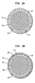
- FIG 2A is a schematic representation of a cross-sectional view of a nuclear fuel rod for a PWR such as shown in Figure 1 constructed according to the teachings of the present invention having a composite cladding 110 comprising an outer layer 111 composed of a corrosion resistant zirconium and/or zirconium alloy metal and an inner layer 114 bonded metallurgically to inner wall 113 of outer layer 111 and composed of a zirconium alloy consisting essentially of molybdenum and 3 to 6 weight percent bismuth and the balance zirconium, and preferably where the amount of molybdenum is in the range of 0.5 to 1.5 weight percent.
- a composite cladding 110 comprising an outer layer 111 composed of a corrosion resistant zirconium and/or zirconium alloy metal and an inner layer 114 bonded metallurgically to inner wall 113 of outer layer 111 and composed of a zirconium alloy consisting essentially of molybdenum and 3 to 6 weight percent bismuth and the balance zircon
- the inner layer 114 is made from another zirconium alloy consisting essentially of molybdenum, niobium, and 3 to 6 weight percent bismuth and the balance zirconium, and preferably where the amount of molybdenum is in the range of 0.5 to 1.5 weight percent and the amount of niobium is in the range of 0.5 to 3 weight percent.
- inner layer 114 is composed of a zirconium alloy consisting essentially of 1.5 to 6 weight percent bismuth and 1 to 4 weight percent tin, the balance zirconium.
- inner layer 114 is composed of a zirconium alloy consisting essentially of molybdenum and 1.5 to 6 weight percent bismuth and 1 to 4 weight percent tin, the balance zirconium.
- inner layer 114 is composed of a zirconium alloy consisting essentially of molybdenum, niobium, and 1.5 to 6 weight percent bismuth and 1 to 4 weight percent tin, the balance zirconium, and preferably where the amount of molybdenum ranges from 0.5 to 1.5 weight percent and the amount of niobium ranges from 0.5 to 3 weight percent.
- inner layer is composed of a zirconium alloy consisting essentially of 1.5 to 3 weight percent bismuth, 0.5 to 3 weight percent niobium, 0.5 to 1.5 weight percent molybdenum, the balance zirconium, where the sum of the amounts of niobium and molybdenum is greater than 1.5 weight percent.
- FIG 2B is a schematic representation of a cross-sectional view of another nuclear fuel rod for a PWR such as shown in Figure 1 constructed according to the teachings of the present invention having a composite cladding 120 comprising an outer layer 121 composed of a corrosion resistant zirconium and/or zirconium alloy metal, an inner layer 124 composed a high strength zirconium alloy and an innermost layer 127 or liner bonded metallurgically on the inside surface 126 of the inner layer 124.
- a composite cladding 120 comprising an outer layer 121 composed of a corrosion resistant zirconium and/or zirconium alloy metal, an inner layer 124 composed a high strength zirconium alloy and an innermost layer 127 or liner bonded metallurgically on the inside surface 126 of the inner layer 124.
- inner layer 124 of composite cladding 120 is composed of a high strength zirconium alloy consisting essentially of molybdenum and 3 to 6 weight percent bismuth and the balance zirconium, and preferable where the amount of molybdenum is in the range of 0.5 to 1.5 weight percent.
- the inner layer 124 is made from another zirconium alloy consisting essentially of molybdenum, niobium, and 3 to 6 weight percent bismuth and the balance zirconium, and preferably where the amount of molybdenum is in the range of 0.5 to 1.5 weight percent and the amount of niobium is in the range of 0.5 to 3 weight percent.
- inner layer 124 is composed of a zirconium alloy consisting essentially of 1.5 to 6 weight percent bismuth and 1 to 4 weight percent tin, the balance zirconium.
- inner layer 124 is composed of a zirconium alloy consisting essentially of molybdenum and 1.5 to 6 weight percent bismuth and 1 to 4 weight percent tin, the balance zirconium.
- inner layer 124 is composed of a zirconium alloy consisting essentially of molybdenum, niobium, and 1.5 to 6 weight percent bismuth and 1 to 4 weight percent tin, the balance zirconium, and preferably where the amount of molybdenum ranges from 0.5 to 1.5 weight percent and the amount of niobium ranges from 0.5 to 3 weight percent.
- inner layer 124 is composed of a zirconium alloy consisting essentially of 1.5 to 3 weight percent bismuth, 0.5 to 3 weight percent niobium, 0.5 to 1.5 weight percent molybdenum, the balance zirconium, where the sum of the amounts of niobium and molybdenum is greater than 1.5 weight percent.
- innermost layer 127 can be zirconium or a zirconium alloy, or another metal and preferably is made of pure or sponge zirconium or a dilute zirconium iron alloy of about 0.4 weight percent iron.
Landscapes
- Engineering & Computer Science (AREA)
- Physics & Mathematics (AREA)
- Metallurgy (AREA)
- Plasma & Fusion (AREA)
- General Engineering & Computer Science (AREA)
- High Energy & Nuclear Physics (AREA)
- Laminated Bodies (AREA)
- Powder Metallurgy (AREA)
- Organic Low-Molecular-Weight Compounds And Preparation Thereof (AREA)
- Monitoring And Testing Of Nuclear Reactors (AREA)
Claims (8)
- Hochfestigkeitsmantelrohr (10) für nuklearen Brennstoff für einen wassergekühlten und/oder moderierten nuklearen Reaktor umfassend:Eine längliche hohle metallische rohrförmige Ummantelung (110; 120) zur Aufnahme eines nuklearen Brennstoffs (80), die rohrförmige Ummantelung (110; 120) umfassend:eine äußere rohrförmige Schicht (111; 121) mit einer äußeren Wand und einer inneren Wand (113), die äußere rohrförmige Schicht (111; 121) gebildet aus einer Zirkonlegierung, eine innere rohrförmige Schicht (114; 124), die an die innere Wand (113) der äußeren rohrförmigen Schicht (111; 121) gebondet ist, dadurch gekennzeichnet, dass die innere rohrförmige Schicht (114;. 124) aus einer Hochfestigkeitszirkonlegierung gebildet ist, die 1,5 bis 6 Gew. % Wismut, wenigstes eine der Komponenten Molybdän und Zinn, und den Rest im wesentlichen Zirkon enthält.
- Das Mantelrohr wie in Anspruch 1, wobei die Legierung der inneren rohrförmigen Schicht (114; 124) 1 bis 4 Gew. % Zinn enthält.
- Das Mantelrohr wie in Anspruch 2, wobei die Legierung der inneren rohrförmigen Schicht (114; 124) des weiteren Niob enthält, vorzugsweise 0,5 bis 3 Gew. %, wodurch die Gewichtsprozente des Zirkon um die Menge der Gew. % des Niobs entsprechend reduziert wird.
- Das Mantelrohr wie in Anspruch 3, wobei die Legierung der inneren rohrförmigen Schicht (114; 124) enthält 1,5 bis 3 Gew. % Wismut, 0,5 bis 3 Niob und die Summe aus Niob und Molybdän größer als 1,5 ist, wodurch die Gewichtsprozente des Zirkon um eine entsprechende Menge der Summe der Gewichtsprozente des Niobs und des Molybdäns reduziert wird.
- Das Mantelrohr wie in den Ansprüchen 1, 2 oder 3, wobei die Menge des Molybdäns zwischen 0,5 und 1,5 Gew. % beträgt.
- Mantelrohr wie in Anspruch 1 oder 3, wobei die Menge an Wismut 3 bis 6 Gew. % ist.
- Das Mantelrohr wie in einem der vorherigen Ansprüche, wobei die rohrförmige Ummantelung (110; 120) weiterhin eine innerste Schicht (127) aufweist, die an eine innere Wand (113) der inneren Schicht (114; 124) gebondet ist.
- Das Mantelrohr wie in Anspruch 7, wobei die innerste Schicht (127) durch. ein Metall gebildet wird, welches aus der Gruppe umfassend Zirkon und Zirkonlegierungen gewählt ist.
Applications Claiming Priority (2)
| Application Number | Priority Date | Filing Date | Title |
|---|---|---|---|
| US823500 | 1992-01-22 | ||
| US08/823,500 US5790623A (en) | 1997-03-25 | 1997-03-25 | Composite cladding for nuclear fuel rods |
Publications (2)
| Publication Number | Publication Date |
|---|---|
| EP0867888A1 EP0867888A1 (de) | 1998-09-30 |
| EP0867888B1 true EP0867888B1 (de) | 2003-01-22 |
Family
ID=25238940
Family Applications (1)
| Application Number | Title | Priority Date | Filing Date |
|---|---|---|---|
| EP98104909A Expired - Lifetime EP0867888B1 (de) | 1997-03-25 | 1998-03-18 | Verbundhüllrohr für Kernreaktorbrennstäbe |
Country Status (7)
| Country | Link |
|---|---|
| US (1) | US5790623A (de) |
| EP (1) | EP0867888B1 (de) |
| JP (1) | JPH10282277A (de) |
| KR (1) | KR19980080622A (de) |
| DE (1) | DE69810832T2 (de) |
| ES (1) | ES2193429T3 (de) |
| TW (1) | TW373185B (de) |
Families Citing this family (5)
| Publication number | Priority date | Publication date | Assignee | Title |
|---|---|---|---|---|
| SE513185C2 (sv) * | 1998-12-11 | 2000-07-24 | Asea Atom Ab | Zirkoniumbaserad legering och komponent i en kärnenergianläggning |
| JP3510211B2 (ja) | 1999-03-29 | 2004-03-22 | フラマトム アンプ ゲゼルシャフト ミット ベシュレンクテル ハフツング | 加圧水炉の燃料棒用の被覆管およびその被覆管の製造方法 |
| SE530673C2 (sv) * | 2006-08-24 | 2008-08-05 | Westinghouse Electric Sweden | Vattenreaktorbränslekapslingsrör |
| US9406406B2 (en) | 2011-12-12 | 2016-08-02 | Bwxt Nuclear Energy, Inc. | Control rod with outer hafnium skin |
| US10217533B2 (en) * | 2013-08-30 | 2019-02-26 | Electric Power Research Institute, Inc. | Fuel rod cladding and methods for making and using same |
Family Cites Families (12)
| Publication number | Priority date | Publication date | Assignee | Title |
|---|---|---|---|---|
| DE3528545A1 (de) * | 1985-08-08 | 1987-02-19 | Kraftwerk Union Ag | Brennstab fuer ein kernreaktorbrennelement |
| US5176762A (en) * | 1986-01-02 | 1993-01-05 | United Technologies Corporation | Age hardenable beta titanium alloy |
| TW223124B (de) * | 1987-04-23 | 1994-05-01 | Gen Electric | |
| US4876064A (en) * | 1987-04-23 | 1989-10-24 | General Electric Company | Corrosion resistant zirconium alloys containing bismuth |
| DE3863864D1 (de) * | 1987-07-21 | 1991-08-29 | Siemens Ag | Brennstab fuer ein kernreaktorbrennelement. |
| JPH02173235A (ja) * | 1988-12-27 | 1990-07-04 | Toshiba Corp | 耐食性ジルコニウム合金 |
| US5026516A (en) * | 1989-05-25 | 1991-06-25 | General Electric Company | Corrosion resistant cladding for nuclear fuel rods |
| US5024809A (en) * | 1989-05-25 | 1991-06-18 | General Electric Company | Corrosion resistant composite claddings for nuclear fuel rods |
| US5190721A (en) * | 1991-12-23 | 1993-03-02 | General Electric Company | Zirconium-bismuth-niobium alloy for nuclear fuel cladding barrier |
| JP3215112B2 (ja) * | 1992-03-13 | 2001-10-02 | シーメンス アクチエンゲゼルシヤフト | 二層型被覆管を有する原子炉燃料棒 |
| US5341407A (en) * | 1993-07-14 | 1994-08-23 | General Electric Company | Inner liners for fuel cladding having zirconium barriers layers |
| JP3094778B2 (ja) * | 1994-03-18 | 2000-10-03 | 株式会社日立製作所 | 軽水炉用燃料集合体とそれに用いられる部品及び合金並びに製造法 |
-
1997
- 1997-03-25 US US08/823,500 patent/US5790623A/en not_active Expired - Fee Related
-
1998
- 1998-03-09 TW TW087103414A patent/TW373185B/zh active
- 1998-03-18 DE DE69810832T patent/DE69810832T2/de not_active Expired - Fee Related
- 1998-03-18 ES ES98104909T patent/ES2193429T3/es not_active Expired - Lifetime
- 1998-03-18 EP EP98104909A patent/EP0867888B1/de not_active Expired - Lifetime
- 1998-03-24 JP JP10075481A patent/JPH10282277A/ja active Pending
- 1998-03-25 KR KR1019980010227A patent/KR19980080622A/ko not_active Application Discontinuation
Also Published As
| Publication number | Publication date |
|---|---|
| EP0867888A1 (de) | 1998-09-30 |
| DE69810832T2 (de) | 2003-12-24 |
| KR19980080622A (ko) | 1998-11-25 |
| ES2193429T3 (es) | 2003-11-01 |
| TW373185B (en) | 1999-11-01 |
| DE69810832D1 (de) | 2003-02-27 |
| US5790623A (en) | 1998-08-04 |
| JPH10282277A (ja) | 1998-10-23 |
Similar Documents
| Publication | Publication Date | Title |
|---|---|---|
| US5026516A (en) | Corrosion resistant cladding for nuclear fuel rods | |
| US5373541A (en) | Nuclear fuel rod and method of manufacturing the cladding of such a rod | |
| US5024809A (en) | Corrosion resistant composite claddings for nuclear fuel rods | |
| US6243433B1 (en) | Cladding for use in nuclear reactors having improved resistance to stress corrosion cracking and corrosion | |
| EP0468093A1 (de) | Korrosionsfeste Zirkoniumlegierung | |
| US5787142A (en) | Pressurized water reactor nuclear fuel assembly | |
| US5768332A (en) | Nuclear fuel rod for pressurized water reactor | |
| EP0867888B1 (de) | Verbundhüllrohr für Kernreaktorbrennstäbe | |
| EP0735151B1 (de) | Legierung zur Verbesserung der Korrosionsbeständigkeit von Kernreaktorbauteile | |
| US5772798A (en) | High strength zirconium alloys containing bismuth | |
| US6511556B1 (en) | High strength zirconium alloys containing bismuth and niobium | |
| EP0964407B1 (de) | Hochfeste Zirkonlegierungen enthaltend Wismut, Zinn und Niob | |
| EP3907742B1 (de) | Hüllrohr für einen brennstab für einen kernreaktor, brennstab und brennelement |
Legal Events
| Date | Code | Title | Description |
|---|---|---|---|
| PUAI | Public reference made under article 153(3) epc to a published international application that has entered the european phase |
Free format text: ORIGINAL CODE: 0009012 |
|
| AK | Designated contracting states |
Kind code of ref document: A1 Designated state(s): BE DE ES FR GB SE |
|
| AX | Request for extension of the european patent |
Free format text: AL;LT;LV;MK;RO;SI |
|
| 17P | Request for examination filed |
Effective date: 19990322 |
|
| AKX | Designation fees paid |
Free format text: BE DE ES FR GB SE |
|
| 17Q | First examination report despatched |
Effective date: 20000313 |
|
| RAP1 | Party data changed (applicant data changed or rights of an application transferred) |
Owner name: FRAMATOME ANP, INC. |
|
| GRAG | Despatch of communication of intention to grant |
Free format text: ORIGINAL CODE: EPIDOS AGRA |
|
| GRAG | Despatch of communication of intention to grant |
Free format text: ORIGINAL CODE: EPIDOS AGRA |
|
| GRAH | Despatch of communication of intention to grant a patent |
Free format text: ORIGINAL CODE: EPIDOS IGRA |
|
| GRAH | Despatch of communication of intention to grant a patent |
Free format text: ORIGINAL CODE: EPIDOS IGRA |
|
| GRAA | (expected) grant |
Free format text: ORIGINAL CODE: 0009210 |
|
| AK | Designated contracting states |
Kind code of ref document: B1 Designated state(s): BE DE ES FR GB SE |
|
| REG | Reference to a national code |
Ref country code: GB Ref legal event code: FG4D |
|
| REF | Corresponds to: |
Ref document number: 69810832 Country of ref document: DE Date of ref document: 20030227 Kind code of ref document: P |
|
| PGFP | Annual fee paid to national office [announced via postgrant information from national office to epo] |
Ref country code: FR Payment date: 20030310 Year of fee payment: 6 |
|
| PGFP | Annual fee paid to national office [announced via postgrant information from national office to epo] |
Ref country code: GB Payment date: 20030312 Year of fee payment: 6 |
|
| PGFP | Annual fee paid to national office [announced via postgrant information from national office to epo] |
Ref country code: DE Payment date: 20030327 Year of fee payment: 6 |
|
| PGFP | Annual fee paid to national office [announced via postgrant information from national office to epo] |
Ref country code: ES Payment date: 20030409 Year of fee payment: 6 |
|
| REG | Reference to a national code |
Ref country code: SE Ref legal event code: TRGR |
|
| PGFP | Annual fee paid to national office [announced via postgrant information from national office to epo] |
Ref country code: BE Payment date: 20030522 Year of fee payment: 6 |
|
| ET | Fr: translation filed | ||
| REG | Reference to a national code |
Ref country code: ES Ref legal event code: FG2A Ref document number: 2193429 Country of ref document: ES Kind code of ref document: T3 |
|
| PLBE | No opposition filed within time limit |
Free format text: ORIGINAL CODE: 0009261 |
|
| STAA | Information on the status of an ep patent application or granted ep patent |
Free format text: STATUS: NO OPPOSITION FILED WITHIN TIME LIMIT |
|
| 26N | No opposition filed |
Effective date: 20031023 |
|
| PG25 | Lapsed in a contracting state [announced via postgrant information from national office to epo] |
Ref country code: GB Free format text: LAPSE BECAUSE OF NON-PAYMENT OF DUE FEES Effective date: 20040318 |
|
| PG25 | Lapsed in a contracting state [announced via postgrant information from national office to epo] |
Ref country code: SE Free format text: LAPSE BECAUSE OF NON-PAYMENT OF DUE FEES Effective date: 20040319 |
|
| PG25 | Lapsed in a contracting state [announced via postgrant information from national office to epo] |
Ref country code: ES Free format text: LAPSE BECAUSE OF NON-PAYMENT OF DUE FEES Effective date: 20040320 |
|
| PG25 | Lapsed in a contracting state [announced via postgrant information from national office to epo] |
Ref country code: BE Free format text: LAPSE BECAUSE OF NON-PAYMENT OF DUE FEES Effective date: 20040331 |
|
| BERE | Be: lapsed |
Owner name: *FRAMATOME ANP INC. Effective date: 20040331 |
|
| PG25 | Lapsed in a contracting state [announced via postgrant information from national office to epo] |
Ref country code: DE Free format text: LAPSE BECAUSE OF NON-PAYMENT OF DUE FEES Effective date: 20041001 |
|
| EUG | Se: european patent has lapsed | ||
| GBPC | Gb: european patent ceased through non-payment of renewal fee |
Effective date: 20040318 |
|
| PG25 | Lapsed in a contracting state [announced via postgrant information from national office to epo] |
Ref country code: FR Free format text: LAPSE BECAUSE OF NON-PAYMENT OF DUE FEES Effective date: 20041130 |
|
| REG | Reference to a national code |
Ref country code: FR Ref legal event code: ST |
|
| REG | Reference to a national code |
Ref country code: ES Ref legal event code: FD2A Effective date: 20040320 |
|
| PGFP | Annual fee paid to national office [announced via postgrant information from national office to epo] |
Ref country code: SE Payment date: 20030326 Year of fee payment: 6 |