EP0867162A2 - Gewichtentlastender Laufgipsverband für den Unterschenkel und Verfahen zu seiner Herstellung - Google Patents
Gewichtentlastender Laufgipsverband für den Unterschenkel und Verfahen zu seiner Herstellung Download PDFInfo
- Publication number
- EP0867162A2 EP0867162A2 EP97105063A EP97105063A EP0867162A2 EP 0867162 A2 EP0867162 A2 EP 0867162A2 EP 97105063 A EP97105063 A EP 97105063A EP 97105063 A EP97105063 A EP 97105063A EP 0867162 A2 EP0867162 A2 EP 0867162A2
- Authority
- EP
- European Patent Office
- Prior art keywords
- cast
- patient
- foot
- sole
- lower leg
- Prior art date
- Legal status (The legal status is an assumption and is not a legal conclusion. Google has not performed a legal analysis and makes no representation as to the accuracy of the status listed.)
- Granted
Links
Images


Classifications
-
- A—HUMAN NECESSITIES
- A61—MEDICAL OR VETERINARY SCIENCE; HYGIENE
- A61F—FILTERS IMPLANTABLE INTO BLOOD VESSELS; PROSTHESES; DEVICES PROVIDING PATENCY TO, OR PREVENTING COLLAPSING OF, TUBULAR STRUCTURES OF THE BODY, e.g. STENTS; ORTHOPAEDIC, NURSING OR CONTRACEPTIVE DEVICES; FOMENTATION; TREATMENT OR PROTECTION OF EYES OR EARS; BANDAGES, DRESSINGS OR ABSORBENT PADS; FIRST-AID KITS
- A61F13/00—Bandages or dressings; Absorbent pads
- A61F13/04—Plaster of Paris bandages; Other stiffening bandages
- A61F13/041—Accessories for stiffening bandages, e.g. cast liners, heel-pieces
- A61F13/043—Shoe-like cast covers; Cast socks
Definitions
- the present invention relates to lower leg load removing and walking casts used for treatment of tibial fractures, that is, casts applied to an affected leg, and a method of making the same.
- PTB casts Pier Tendon Bearing casts, so-called walking casts for lower leg
- tibial fractures fracture of leg bone
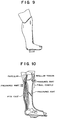
- This cast is used for bearing a patient's human body weight at pressured parts around the knee joint (portions of the patellar tendon and tibial condyle) shown with arrows in Fig.10 in order to enable a knee joint to move or walk with a working cast after having treated the leg bone or at an early period after a surgical operation, thereby protecting the tibial fractured portion so as not to effect an excessive load thereon.
- Prior art lower leg casts are also known where the cast portion surrounding the lower leg is short and does not reach the area adjacent the knee of a patient and the rear part adjacent the knee. See, U.S. patent No. 2,875,752 by Lovich dated March 3, 1959. Such casts cannot result in reducing the loads applied to the lower leg, even if a space were formed between the foot and bottom of the cast during the preparation of the cast, since the leg is not suspended or supported by the cast adjacent the knee. Such casts are not effective to reduce the load on the lower leg and are not as effective as even the prior art PTB casts described above.
- the present invention has been designed to provide casts which excel in the load removing effect.
- trumpet shaped instrument Imagine a morning-glory or trumpet shaped instrument. If a hand is inserted into the instrument at a flared mouth thereof, the arm is held by a conical interior of the instrument and can no further move ahead.
- the trumpet shaped instrument corresponds to the cast
- the arm corresponds to the affected leg.
- a force making the hand go farther corresponds to a load by the body weight.
- the prior art intended that the leg was supported in the interior cavity of the cast which was presumed as the hollow conical column.
- the cast and the leg are very imperfect figures as conical bodies, a dynamic bearing power is limited in itself, and the leg somewhat slides within the cast due to the body weight toward the sole of the foot.
- the load removing lower leg cast of the prior art supports, at an upper portion of the lower leg part of the cast surrounding the entire part of the patient's lower leg, only a portion of the reactive forces caused by the patient's walking, and all of the remaining part of the loading forces are received at the interior bottom of the cast, bearing against the sole of a patient's foot, so that a satisfactory load removing effect could not be provided.
- the reactive loading force at the interior bottom of the cast is removed by the space between the sole of the foot and the bottom of the cast, and is also received at the upper portion of the lower leg cast in accordance with the morning-glory or trumpet theory mentioned above, thereby obtaining the effect of canceling the absolute total amount of the reactive loading forces acting upon the foot and the tibial fractured part, that is, a sufficient load removing effect is achieved. Further, when the size of the space is changed, the load removing effect may also be controlled.
- the present invention has been devised on the basis of a new finding, wherein a casting plaster is surrounded around the patient's leg such that a predetermined space is formed between the sole of the foot and the bottom of the cast.
- the cast prepared by the invention has excellent load removing and walking effect.
- members to be arranged for the space it is possible to, if applicable to the sole of the foot, employ various kinds of existing members including plate shapes (10 to 30 mm thickness), box shapes, and if incorporating absorption function when shocking of the load, bellows bags, sponge or spring as illustrated and stated later are preferable.
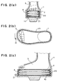
- Fig.2 shows the condition of the cast provided by the first embodiment in use, in which Fig.2(a) is a front view of this condition, Fig.2(b) is a plan view of the same, and Fig.2(c) is a side view thereof.
- Fig.3 shows the bellows bag, in which Fig.3(a) is a front view of this embodiment, Fig.3(b) is a plan of the same, and Fig.3 (c) is a side view thereof.
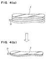
- Fig.4 shows expansion and contraction of the bellows bag, in which Fig.4(a) is a case of the former, and Fig.4(b) is a case of the latter.
- Fig.5 shows a second embodiment in which Fig.5(a) is a cross sectional fron view of this embodiment, Fig.5(b) is a plan view of the same, Fig.5(c) is a side view thereof, and Fig.5(d) is a side view thereof.
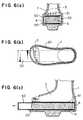
- Fig.6 also shows the second embodiment in which Fig.6(a) is a cross sectional fron view of this embodiment, Fig.6(b) is a plan view of the same, and Fig.6(c) is a side view thereof.
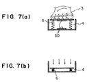
- Fig.7 shows a third embodiment in which Fig.7(a) is a cross sectional front view illustrating an expansion of the spring, and Fig.7(b) is a view illustrating a contraction of the same.
- Fig.8 shows a fourth embodiment in which Fig.8(a) is a perspective view of this embodiment, Fig.8(b) is a side view of the same, and Fig.8(c) is a view showing the use thereof.
- Fig.9 is an explanatory view showing a conventional leg cast (PTB cast).
- Fig.10 shows parts aiming at supporting of a patient's human body weight (pressuring parts) in the above conventional leg cast (PTB cast), the supporting and pressurized portion of the cast also used in the above embodiments of the present invention.
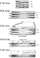
- Fig.11 shows a fifth embodiment in which Fig.11(a) is a side view of this embodiment, Fig.11(b) is a side view of the same, Fig.11(c) is a side view of the same, Fig.11(d) is a side view thereof, and Fig.11(e) is a side view thereof.
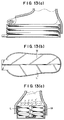
- Fig.13 shows a seventh embodiment in which Fig.13(a) is a side view of this embodiment, Fig.13(b) is a plan view of the same and Fig.13(c) is a front view thereof; and
- Fig.8 shows a most basic embodiment of this invention, from which other embodiments are derived. However for easy understanding of the invention, explanation will be made with Fig.8 as a fourth embodiment.
- the bellows bag 2 is closed at an air hole 21 as seen in Fig.3 and is disposed within a protecting case 20 comprising a hard resin as illustrated in Fig.1.
- a foot 3 is then put on the bellows bag 2, followed by wrapping the casting plaster on the foot in an ordinary sequence and hardening it.
- wrapping and hardening the casting plaster a considerable pressure is burdened on the bellows bag 2, however it may perfectly maintain its shape against the pressuring force, since it is placed within the hard protecting case 20 and the air hole 21 is tightened or closed.
- the air hole 21 is opened after the plaster 1 is solidified, the bellows bag 2 is made to freely expand and contract as is seen in Fig.4, and the load removing and walking cast having excellent load removing effect is accomplished.
- the protecting case 20 serves to protect the soft and elastic bellows bag 2 against the cast 1 wrapped around the patient's leg, and due to this protecting service, the bellows bag 2 may expand and contract vertically (along the length of the shin bone) even by a weak pressure within the cast 1.
- the space 4 exists between the sole of the foot 3 and the bottom 10 of the cast 1, and the protecting case 20 made of the hard synthetic resin is disposed in the space 4, within which the bellows bag 2 is placed.
- the bellows bag 2 communicates with the exterior through the air hole 21, and expands and contracts in response to moving of the foot as the patient walks as burdened. Therefore, when walking with the present cast 1, the bellows bag 2 placed in the space 4 is pressured and easily shrinked, and the foot 3 may moderately or slightly move along the length of the shin bone (in the loading direction) within the space 4, and this moving partially absorbs the loading force by the walking burden.
- a sufficient load removing effect may be provided.
- the leg of a patient is thus suspended by the shape of the cast with respect to the leg together with the pressure of the cast with respect to the leg adjacent the front and rear parts of the knee. That is, due to the shape of the cast and the catching or holding of the lower leg at the knee and the rear part of the knee by the cast, the leg is suspended and does not slide down, or slides down only slightly less than the distance of the space that is formed between the sole of the foot and the interior bottom portion of the cast.
- Figs.5 and 6 illustrate a second embodiment
- Fig.7 shows a third embodiment, and these embodiments employ the sponge and the spring respectively, in place of the bellows bag 2 of the first embodiment.
- a space holding or maintaining instrument 50 is inserted into a front opening part of the protecting case 20, said space holding instrument being of a rectangle opening one of vertical sides in cross section ( ⁇ ) and holding a sponge 5 with its upper and lower sides.
- a bottom plate 51 is placed on an upper plate of the space holding instrument 50, and the foot 3 is put on the bottom plate 51, followed by wrapping the casting plaster around the patient's foot by the ordinary means.
- the space holding instrument 50 is removed after the plaster has been solidified. Then, the space 4 appears between the sole of the foot 3 and the bottom of the cast 1, and the sponge 5 elastically acts within the space 4. Thus, the cast is completed.
- the process of the third embodiment is similar to the second embodiment, in which depending upon the space holding instrument 50, the space 4 appears, similarly therebetween, and a spring 5 expands and contracts within the space 4.
- the foot 3 when walking, may moderately move or slide slightly within the cast along the length of the shin bone (in the loading direction), so that the loading force caused by the walking burden is fully absorbed.
- Fig.8 illustrates a fourth embodiment. As shown in Fig.8(c), a space is formed between the sole of a patient's foot and the interior bottom base portion of the cast. A similar space is also formed in the first to third embodiments, in which, however, the elastic member is interposed in the space so as to control the load removing and walking effect.
- the substantially L-shaped member 7 is used to form the space between the sole of the foot 3 and the bottom of the cast 1 during the preparation of the cast.
- the member or protecting plate 7 of this embodiment is L-shaped in cross section or a bent plate member comprising a side 70 contacting a heel of the foot, and slightly above near the calf, and a bottom 71 forming a substantially planar base and contacting the bottom of the cast 1 after the cast is solidified.
- the process for preparing the cast of this embodiment brings the heel to the side 70 such that a space is formed between the sole of the foot 3 and the bottom 71 of the protecting plate, and it is sufficient to wrap and solidify the casting plaster under a condition that the lower portion of the side 70 extends further downward than the heel so as to form the space 4.
- a cast like a morning-glory or trumpet is formed leaving the space between the sole of the foot and the bottom of the protecting plate 7 as seen in Fig.8(c).
- the sole of the foot does not contact the bottom 71 due to suspending the lower leg by holding the lower leg at the knee and its adjacent parts, so that the space 4 is maintained during walking.
- the reactive forces caused by walking are taken up through the cast and are at least partially borne at the upper portions of the lower leg adjacent the knee (front and rear), as previously described.
- Fig.8 does not employ any intermediates such as the bellows, the spring or the sponge between the sole of the foot and the bottom of the cast, however the cast of this embodiment can also make a space for avoiding the push-up, and bring about the satisfied load removing and walking effect by moving of the foot within the space while walking.
- leg casts provided by means of the invention bring about remarkable results to largely improve the load removing and walking effect.
- the cast of the present invention can extend above the knee and may extend to the hip. Such a cast may support the hip bone and provide load removal upon the entire leg including load removal at the thigh.
- the embodiments using the elastic member provide for controlling the load removing effect.
- the elastic member which may vary the space, controls the load removing effect. That is, for healing the tibial fracture, a sufficient load removing effect is required immediately after suffering the tibial fracture. It is said that a callous appears around the fractured part as time goes on, and a moderate burden upon the fractured part advantageously acts on the bone formation.
- the prior art cast did not bring about a sufficient load removing effect required at the beginning period of curing the fractured bone, and, further, it was impossible to control the load removing effect in accordance with the curing progress.
- the load removing effect can be varied by changing the thickness of the elastic member. Therefore, if using the elastic members of different thicknesses in response to the curing progress, the load removing effect may be controlled, and it may be served as an optimum curing instrument.
- the present invention proposes bellows bags as illustrated in Figs.11 to 14 as further embodiments for controlling load removing effects. These new embodiments have been further improved of the bellows bags shown in Figs.1 to 4.
- a first using embodiment is that the bellows is divided into a plurality of upper and lower independent spaces by means of interior isolating walls.
- Fig.11 shows that the bellows is divided into independent three spaces A1, A2, A3 by the interior partitioning walls, and each of the spaces is equipped with a one air hole, whereby the bellows can be shrinked (shortened in width) by selectively operating the air hole, that is, the spaces for the foot's sliding are enlarged three stepwise. If the air hole is provided with a re-sealing stopper, an arbitrary space which has once been opened at the air hole and shrinked, is again expanded by introducing the air, so that the width of the space may be reduced.
- FIG.11 shows the bellows prior to opening the air hole, where the spaces A1, A2 and A3 are elongated due to the pressure of the enclosed air.
- (c) shows that the air hole of the space A1 is opened and only the space A1 is shrinked (shortened) to provide a space 1.
- (d) shows that the air holes of the spaces A1, A2 are opened
- (e) shows that the air holes of the spaces A1, A2, A3 are opened, and the space A1+A2 and the space A1+A2+A3 are obtained, respectively.
- the air hole is provided with the re-sealing stopper, it is possible to return the shrinked bellows to an elongated state as a sequence of (e) ⁇ (d) ⁇ (c) ⁇ (b), and as a result such a load removing effect may be optionally provided alongside a curing progress while maintaining the bellows within the cast which does not require remaking.
- a second embodiment illustrated in Fig.12 are the bellows divided into two parts A and P of back and forth.
- side walls of the two bellows face one another therebetween, differently from the first embodiment.
- two bellows have individual air holes, each of them may be shortened or elongated indepedently.
- the instant embodiment may be clinically used to bone fractures at front parts of foot or heel (rear part of foot). That is, if the bellows A of the front part is shortened, a load is burdened on the not shortened bellows P of the heel part, and thus the load is removed from the foot front part, and reversely if the rear bellows (the space) is shortened, the load is effected on the front part and the heel is removed from the load.
- Fig.13 shows a third embodiment that the bellows is divided at center longitudinally into independent right M and left L.
- the two bellows have independent air holes, and each of them may be shortened or elongated independently as the second embodiment does.
- This embodiment is used when the inner part of the foot (i.e. a great toe) or the outer part (i.e. a little toe) is selectively effected with load removal.
- a part to be removed from load is shortened (shrinked).
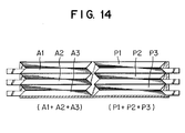
- Fig.14 shows a fourth embodiment which is combined with the second embodiment or the first + third embodiments. Although a structure is complicated, the load may be removed per each of the independent bellows.
Landscapes
- Health & Medical Sciences (AREA)
- Engineering & Computer Science (AREA)
- Biomedical Technology (AREA)
- Heart & Thoracic Surgery (AREA)
- Vascular Medicine (AREA)
- Life Sciences & Earth Sciences (AREA)
- Animal Behavior & Ethology (AREA)
- General Health & Medical Sciences (AREA)
- Public Health (AREA)
- Veterinary Medicine (AREA)
- Prostheses (AREA)
- Orthopedics, Nursing, And Contraception (AREA)
- Footwear And Its Accessory, Manufacturing Method And Apparatuses (AREA)
Priority Applications (2)
| Application Number | Priority Date | Filing Date | Title |
|---|---|---|---|
| EP19970105063 EP0867162B1 (de) | 1997-03-25 | 1997-03-25 | Gewichtentlastender Laufgipsverband für den Unterschenkel |
| DE1997615146 DE69715146T2 (de) | 1997-03-25 | 1997-03-25 | Gewichtentlastender Laufgipsverband für den Unterschenkel |
Applications Claiming Priority (1)
| Application Number | Priority Date | Filing Date | Title |
|---|---|---|---|
| EP19970105063 EP0867162B1 (de) | 1997-03-25 | 1997-03-25 | Gewichtentlastender Laufgipsverband für den Unterschenkel |
Publications (3)
| Publication Number | Publication Date |
|---|---|
| EP0867162A2 true EP0867162A2 (de) | 1998-09-30 |
| EP0867162A3 EP0867162A3 (de) | 1999-06-23 |
| EP0867162B1 EP0867162B1 (de) | 2002-09-04 |
Family
ID=8226633
Family Applications (1)
| Application Number | Title | Priority Date | Filing Date |
|---|---|---|---|
| EP19970105063 Expired - Lifetime EP0867162B1 (de) | 1997-03-25 | 1997-03-25 | Gewichtentlastender Laufgipsverband für den Unterschenkel |
Country Status (2)
| Country | Link |
|---|---|
| EP (1) | EP0867162B1 (de) |
| DE (1) | DE69715146T2 (de) |
Family Cites Families (5)
| Publication number | Priority date | Publication date | Assignee | Title |
|---|---|---|---|---|
| US2264570A (en) * | 1940-08-09 | 1941-12-02 | Holden Eugene Paul | Crutch |
| CH273249A (de) * | 1950-03-04 | 1951-01-31 | Schuetz Fritz | Gehbügel für Gipsverbände. |
| GB803642A (en) * | 1954-06-29 | 1958-10-29 | Kenneth Tipper | Improved surgical leg support |
| US2875752A (en) * | 1957-04-08 | 1959-03-03 | Edward L Lovich | Plaster cast |
| US3780728A (en) * | 1972-08-01 | 1973-12-25 | R Stader | Walking device |
-
1997
- 1997-03-25 DE DE1997615146 patent/DE69715146T2/de not_active Expired - Fee Related
- 1997-03-25 EP EP19970105063 patent/EP0867162B1/de not_active Expired - Lifetime
Also Published As
| Publication number | Publication date |
|---|---|
| EP0867162A3 (de) | 1999-06-23 |
| DE69715146D1 (de) | 2002-10-10 |
| EP0867162B1 (de) | 2002-09-04 |
| DE69715146T2 (de) | 2003-04-17 |
Similar Documents
| Publication | Publication Date | Title |
|---|---|---|
| Schatzker | Fractures of the tibial plateau | |
| US4320748A (en) | Fracture brace | |
| US5429588A (en) | Ankle foot orthoses known as lower leg walkers | |
| US4217893A (en) | Above-the-knee cast | |
| US6066107A (en) | Apparatus for the surroundive fixation of extremities | |
| US3680549A (en) | Spiral orthosis for the lower extremity | |
| US4378793A (en) | Removable ankle brace | |
| DE68916642D1 (de) | Stützvorrichtung für fussknöchel. | |
| JP2008523936A (ja) | 補装具 | |
| US20050065458A1 (en) | Splint combined use cast absence for bone fracture fixing | |
| ES2040584T3 (es) | Protesis para el tratamiento dinamico de roturas de ligamentos o distensiones de ligamentos en el tobillo lateral. | |
| JP3371378B2 (ja) | 四肢の包囲固定装置 | |
| US5779656A (en) | Load removing and walking cast for lower leg and method of making the same | |
| US20240016594A1 (en) | Treatment of knee disorders in veterinary medicine | |
| US5800369A (en) | Load removing and walking cast for lower leg | |
| EP0867162A2 (de) | Gewichtentlastender Laufgipsverband für den Unterschenkel und Verfahen zu seiner Herstellung | |
| McCarthy | A method for early spica cast application in treatment of pediatric femoral shaft fractures | |
| CONNOLLY et al. | Closed Reduction and Early Cast-Brace Ambulation in the Treatment of Femoral Fractures: PART I: AN: In Vivo: QUANTITATIVE ANALYSIS OF IMMOBILIZATION IN SKELETAL TRACTION AND A CAST-BRACE | |
| Landsman et al. | Off-loading neuropathic wounds associated with diabetes using an ankle-foot orthosis | |
| Kenzora et al. | Acute management of major trauma involving the foot and ankle with Hoffmann external fixation | |
| Rubin et al. | Prostheses and orthoses for the foot and ankle | |
| RU2111729C1 (ru) | Консервативный функционально-фиксационный способ лечения повреждений голени | |
| KR100186742B1 (ko) | 저압박 깁스 및 그 형성방법 | |
| Birke et al. | Orthopedic walkers: effect on plantar pressures | |
| JPH10263011A (ja) | 免荷ギプス及びその形成方法 |
Legal Events
| Date | Code | Title | Description |
|---|---|---|---|
| PUAI | Public reference made under article 153(3) epc to a published international application that has entered the european phase |
Free format text: ORIGINAL CODE: 0009012 |
|
| AK | Designated contracting states |
Kind code of ref document: A2 Designated state(s): DE FR GB |
|
| PUAL | Search report despatched |
Free format text: ORIGINAL CODE: 0009013 |
|
| 17P | Request for examination filed |
Effective date: 19990319 |
|
| AK | Designated contracting states |
Kind code of ref document: A3 Designated state(s): DE FR GB |
|
| AKX | Designation fees paid |
Free format text: DE FR GB |
|
| 17Q | First examination report despatched |
Effective date: 20010227 |
|
| GRAG | Despatch of communication of intention to grant |
Free format text: ORIGINAL CODE: EPIDOS AGRA |
|
| RTI1 | Title (correction) |
Free format text: LOAD REMOVING WALKING CAST |
|
| GRAG | Despatch of communication of intention to grant |
Free format text: ORIGINAL CODE: EPIDOS AGRA |
|
| GRAG | Despatch of communication of intention to grant |
Free format text: ORIGINAL CODE: EPIDOS AGRA |
|
| GRAH | Despatch of communication of intention to grant a patent |
Free format text: ORIGINAL CODE: EPIDOS IGRA |
|
| GRAG | Despatch of communication of intention to grant |
Free format text: ORIGINAL CODE: EPIDOS AGRA |
|
| GRAH | Despatch of communication of intention to grant a patent |
Free format text: ORIGINAL CODE: EPIDOS IGRA |
|
| GRAA | (expected) grant |
Free format text: ORIGINAL CODE: 0009210 |
|
| AK | Designated contracting states |
Kind code of ref document: B1 Designated state(s): DE FR GB |
|
| REG | Reference to a national code |
Ref country code: GB Ref legal event code: FG4D |
|
| REF | Corresponds to: |
Ref document number: 69715146 Country of ref document: DE Date of ref document: 20021010 |
|
| ET | Fr: translation filed | ||
| PLBE | No opposition filed within time limit |
Free format text: ORIGINAL CODE: 0009261 |
|
| STAA | Information on the status of an ep patent application or granted ep patent |
Free format text: STATUS: NO OPPOSITION FILED WITHIN TIME LIMIT |
|
| 26N | No opposition filed |
Effective date: 20030605 |
|
| PGFP | Annual fee paid to national office [announced via postgrant information from national office to epo] |
Ref country code: GB Payment date: 20040324 Year of fee payment: 8 |
|
| PGFP | Annual fee paid to national office [announced via postgrant information from national office to epo] |
Ref country code: FR Payment date: 20040330 Year of fee payment: 8 |
|
| PGFP | Annual fee paid to national office [announced via postgrant information from national office to epo] |
Ref country code: DE Payment date: 20040517 Year of fee payment: 8 |
|
| PG25 | Lapsed in a contracting state [announced via postgrant information from national office to epo] |
Ref country code: GB Free format text: LAPSE BECAUSE OF NON-PAYMENT OF DUE FEES Effective date: 20050325 |
|
| PG25 | Lapsed in a contracting state [announced via postgrant information from national office to epo] |
Ref country code: DE Free format text: LAPSE BECAUSE OF NON-PAYMENT OF DUE FEES Effective date: 20051001 |
|
| GBPC | Gb: european patent ceased through non-payment of renewal fee |
Effective date: 20050325 |
|
| PG25 | Lapsed in a contracting state [announced via postgrant information from national office to epo] |
Ref country code: FR Free format text: LAPSE BECAUSE OF NON-PAYMENT OF DUE FEES Effective date: 20051130 |
|
| REG | Reference to a national code |
Ref country code: FR Ref legal event code: ST Effective date: 20051130 |