EP0867162B1 - Gewichtentlastender Laufgipsverband für den Unterschenkel - Google Patents
Gewichtentlastender Laufgipsverband für den Unterschenkel Download PDFInfo
- Publication number
- EP0867162B1 EP0867162B1 EP19970105063 EP97105063A EP0867162B1 EP 0867162 B1 EP0867162 B1 EP 0867162B1 EP 19970105063 EP19970105063 EP 19970105063 EP 97105063 A EP97105063 A EP 97105063A EP 0867162 B1 EP0867162 B1 EP 0867162B1
- Authority
- EP
- European Patent Office
- Prior art keywords
- cast
- bellows
- foot
- load
- patient
- Prior art date
- Legal status (The legal status is an assumption and is not a legal conclusion. Google has not performed a legal analysis and makes no representation as to the accuracy of the status listed.)
- Expired - Lifetime
Links
- 239000011505 plaster Substances 0.000 claims description 6
- 229920005989 resin Polymers 0.000 claims description 2
- 239000011347 resin Substances 0.000 claims description 2
- 238000005192 partition Methods 0.000 claims 1
- 230000001681 protective effect Effects 0.000 claims 1
- 230000000694 effects Effects 0.000 description 38
- 210000002683 foot Anatomy 0.000 description 28
- 210000002414 leg Anatomy 0.000 description 24
- 210000001699 lower leg Anatomy 0.000 description 16
- 210000003127 knee Anatomy 0.000 description 13
- 230000037396 body weight Effects 0.000 description 11
- 208000004367 Tibial Fractures Diseases 0.000 description 7
- 230000035876 healing Effects 0.000 description 4
- 210000002303 tibia Anatomy 0.000 description 4
- 208000010392 Bone Fractures Diseases 0.000 description 3
- 238000005266 casting Methods 0.000 description 3
- 210000000629 knee joint Anatomy 0.000 description 3
- 240000001549 Ipomoea eriocarpa Species 0.000 description 2
- 235000005146 Ipomoea eriocarpa Nutrition 0.000 description 2
- 210000000988 bone and bone Anatomy 0.000 description 2
- 210000001930 leg bone Anatomy 0.000 description 2
- 210000000426 patellar ligament Anatomy 0.000 description 2
- 238000007789 sealing Methods 0.000 description 2
- 230000002411 adverse Effects 0.000 description 1
- 230000008602 contraction Effects 0.000 description 1
- 230000007423 decrease Effects 0.000 description 1
- 210000003414 extremity Anatomy 0.000 description 1
- 210000000454 fifth toe Anatomy 0.000 description 1
- 210000001255 hallux Anatomy 0.000 description 1
- 210000001624 hip Anatomy 0.000 description 1
- 210000001981 hip bone Anatomy 0.000 description 1
- 230000011164 ossification Effects 0.000 description 1
- 238000002360 preparation method Methods 0.000 description 1
- 238000004904 shortening Methods 0.000 description 1
- 238000000638 solvent extraction Methods 0.000 description 1
- 239000000725 suspension Substances 0.000 description 1
- 229920003002 synthetic resin Polymers 0.000 description 1
- 239000000057 synthetic resin Substances 0.000 description 1
- 210000000689 upper leg Anatomy 0.000 description 1
Images


Classifications
-
- A—HUMAN NECESSITIES
- A61—MEDICAL OR VETERINARY SCIENCE; HYGIENE
- A61F—FILTERS IMPLANTABLE INTO BLOOD VESSELS; PROSTHESES; DEVICES PROVIDING PATENCY TO, OR PREVENTING COLLAPSING OF, TUBULAR STRUCTURES OF THE BODY, e.g. STENTS; ORTHOPAEDIC, NURSING OR CONTRACEPTIVE DEVICES; FOMENTATION; TREATMENT OR PROTECTION OF EYES OR EARS; BANDAGES, DRESSINGS OR ABSORBENT PADS; FIRST-AID KITS
- A61F13/00—Bandages or dressings; Absorbent pads
- A61F13/04—Plaster of Paris bandages; Other stiffening bandages
- A61F13/041—Accessories for stiffening bandages, e.g. cast liners, heel-pieces
- A61F13/043—Shoe-like cast covers; Cast socks
Definitions
- the present invention relates to lower leg load removing walking casts used for treatment of tibial fractures, that is, casts applied to an affected leg.
- PTB casts Pier Tendon Bearing casts, so-called walking casts for lower leg
- tibial fractures fracture of leg bone
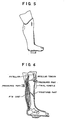
- This cast is used for bearing a patient's human body weight at pressured parts around the knee joint (portions of the patellar tendon and tibial condyle) shown with arrows in Fig.6 in order to enable a knee joint to move or walk with a working cast after having treated the leg bone or at an early period after a surgical operation, thereby protecting the tibial fractured portion so as not to effect an excessive load thereon.
- Prior art lower leg casts are also known where the cast portion surrounding the lower leg is short and does not reach the area adjacent the knee of a patient and the rear part adjacent the knee (US-A 2,875,752). Such casts cannot result in reducing the loads applied to the lower leg, even if a space were formed between the foot and bottom of the cast during the preparation of the cast, since the leg is not suspended or supported by the cast adjacent the knee. Such casts are not effective to reduce the load on the lower leg and are not as effective as even the prior art PTB casts described above.
- trumpet shaped instrument Imagine a morning-glory or trumpet shaped instrument. If a hand is inserted into the instrument at a flared mouth thereof, the arm is held by a conical interior of the instrument and can no further move ahead.
- the trumpet shaped instrument corresponds to the cast
- the arm corresponds to the affected leg.
- a force making the hand go farther corresponds to a load by the body weight.
- the prior art intended that the leg was supported in the interior cavity of the cast which was presumed as the hollow conical column.
- the cast and the leg are very imperfect figures as conical bodies, a dynamic bearing power is limited in itself, and the leg somewhat slides within the cast due to the body weight toward the sole of the foot.
- the load removing lower leg cast of the prior art supports, at an upper portion of the lower leg part of the cast surrounding the entire part of the patient's lower leg, only a portion of the reactive forces caused by the patient's walking, and all of the remaining part of the loading forces are received at the interior bottom of the cast, bearing against the sole of a patient's foot, so that a satisfactory load removing effect could not be provided.
- a walking cast according to the preamble of claim 1 is disclosed in GB-A 803 642.
- the reactive loading force at the interior bottom of the cast is removed by the space between the sole of the foot and the bottom of the cast, and is also received at the upper portion of the lower leg cast in accordance with the morning-glory or trumpet theory mentioned above, thereby obtaining the effect of canceling the absolute total amount of the reactive loading forces acting upon the foot and the tibial fractured part, that is, a sufficient load removing effect is achieved. Further, when the size of the space is changed, the load removing effect may also be controlled.
- the present invention has been devised on the basis of a new finding, wherein a casting plaster is surrounded around the patient's leg such that a predetermined space is formed between the sole of the foot and the bottom of the cast.
- the cast prepared by the invention has excellent load removing and walking effect.
- the cast is formed with a predetermined space therebetween. If the patient walks with the leg cast, the foot can be moved or played in the space along the length of the shin bone (in the loading direction) within a predetermined range. This play absorbs an impact force or the load reactive force which would otherwise adversely influence the fractured bone of the leg, and thus a satisfactory load removing effect is made available.
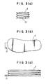
- the bellows bag 2 is closed at an air hole 21 as seen in Fig.3 and is disposed within a protecting case 20 comprising a hard resin as illustrated in Fig.1.
- a foot 3 is then put on the bellows bag 2, followed by wrapping the casting plaster on the foot in an ordinary sequence and hardening it.
- wrapping and hardening the casting plaster a considerable pressure is burdened on the bellows bag 2, however it may perfectly maintain its shape against the pressuring force, since it is placed within the hard protecting case 20 and the air hole 21 is tightened or closed.
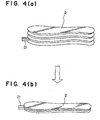
- the air hole 21 is opened after the plaster 1 is solidified, the bellows bag 2 is made to freely expand and contract as is seen in Fig.4, and the load removing and walking cast having excellent load removing effect is accomplished.
- the protecting case 20 serves to protect the soft and elastic bellows bag 2 against the cast 1 wrapped around the patient's leg, and due to this protecting service, the bellows bag 2 may expand and contract vertically (along the length of the shin bone) even by a weak pressure within the cast 1.
- the space 4 exists between the sole of the foot 3 and the bottom 10 of the cast 1, and the protecting case 20 made of the hard synthetic resin is disposed in the space 4, within which the bellows bag 2 is placed.
- the bellows bag 2 communicates with the exterior through the air hole 21, and expands and contracts in response to moving of the foot as the patient walks as burdened. Therefore, when walking with the present cast 1, the bellows bag 2 placed in the space 4 is pressured and easily shrinked, and the foot 3 may moderately or slightly move along the length of the shin bone (in the loading direction) within the space 4, and this moving partially absorbs the loading force by the walking burden.
- a sufficient load removing effect may be provided.
- the leg of a patient is thus suspended by the shape of the cast with respect to the leg together with the pressure of the cast with respect to the leg adjacent the front and rear parts of the knee. That is, due to the shape of the cast and the catching or holding of the lower leg at the knee and the rear part of the knee by the cast, the leg is suspended and does not slide down, or slides down only slightly less than the distance of the space that is formed between the sole of the foot and the interior bottom portion of the cast.
- leg casts provided by means of the invention bring about remarkable results to largely improve the load removing and walking effect.
- the sole of the foot does not contact the bottom due to suspending the lower leg by holding the lower leg at the knee and its adjacent parts, so that a space is maintained during walking.
- the reactive forces caused by walking are taken up through the cast and are at least partially borne at the upper portions of the lower leg adjacent the knee (front and rear), as previously described.
- the cast of the present invention can extend above the knee and may extend to the hip. Such a cast may support the hip bone and provide load removal upon the entire leg including load removal at the thigh.
- the embodiments using the elastic member provide for controlling the load removing effect.
- the elastic member which may vary the space, controls the load removing effect. That is, for healing the tibial fracture, a sufficient load removing effect is required immediately after suffering the tibial fracture. It is said that a callous appears around the fractured part as time goes on, and a moderate burden upon the fractured part advantageously acts on the bone formation.
- the prior art cast according to Fig.5 did not bring about a sufficient load removing effect required at the beginning period of curing the fractured bone, and, further, it was impossible to control the load removing effect in accordance with the curing progress.
- the load removing effect can be varied by changing the thickness of the elastic member. Therefore, if using the elastic members of different thicknesses in response to the curing progress, the load removing effect may be controlled, and it may be served as an optimum curing instrument.
- the present invention proposes bellows bags as illustrated in Figs. 7 to 10 as embodiments for controlling load removing effects. These embodiments constitute improvements of the bellows bags shown in Figs.1 to 4.
- a first using embodiment is that the bellows is divided into a plurality of upper and lower independent spaces by means of interior isolating walls.
- Fig.7 shows that the bellows is divided into independent three spaces A1, A2, A3 by the interior partitioning walls, and each of the spaces is equipped with a one air hole, whereby the bellows can be shrinked (shortened in width) by selectively operating the air hole, that is, the spaces for the foot's sliding are enlarged three stepwise. If the air hole is provided with a re-sealing stopper, an arbitrary space which has once been opened at the air hole and shrinked, is again expanded by introducing the air, so that the width of the space may be reduced.
- FIG.7 shows the bellows prior to opening the air hole, where the spaces A1, A2 and A3 are elongated due to the pressure of the enclosed air.
- (c) shows that the air hole of the space A1 is opened and only the space A1 is shrinked (shortened) to provide a space 1.
- (d) shows that the air holes of the spaces A1, A2 are opened
- (e) shows that the air holes of the spaces A1, A2, A3 are opened, and the space A1+A2 and the space A1+A2+A3 are obtained, respectively.
- the air hole is provided with the re-sealing stopper, it is possible to return the shrinked bellows to an elongated state as a sequence of (e) ⁇ (d) ⁇ (c) ⁇ (b), and as a result such a load removing effect may be optionally provided alongside a curing progress while maintaining the bellows within the cast which does not require remaking.
- the bellows are divided into two parts A and P of back and forth.
- side walls of the two bellows face one another therebetween, differently from the first embodiment. Since two bellows have individual air holes, each of them may be shortened or elongated indepedently.
- the instant embodiment may be clinically used to bone fractures at front parts of foot or heel (rear part of foot). That is, if the bellows A of the front part is shortened, a load is burdened on the not shortened bellows P of the heel part, and thus the load is removed from the foot front part, and reversely if the rear bellows (the space) is shortened, the load is effected on the front part and the heel is removed from the load.
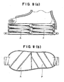
- Fig.9 shows a third embodiment in which the bellows is divided at center longitudinally into independent right M and left L.
- the two bellows have independent air holes, and each of them may be shortened or elongated independently as the second embodiment does.
- This embodiment is used when the inner part of the foot (i.e. a great toe) or the outer part (i.e. a little toe) is selectively effected with load removal.
- a part to be removed from load is shortened (shrinked).
- Fig.10 shows a fourth embodiment which is combined with the second embodiment or the first and third embodiments. Although a structure is complicated, the load may be removed per each of the independent bellows.
Landscapes
- Health & Medical Sciences (AREA)
- Engineering & Computer Science (AREA)
- Biomedical Technology (AREA)
- Heart & Thoracic Surgery (AREA)
- Vascular Medicine (AREA)
- Life Sciences & Earth Sciences (AREA)
- Animal Behavior & Ethology (AREA)
- General Health & Medical Sciences (AREA)
- Public Health (AREA)
- Veterinary Medicine (AREA)
- Prostheses (AREA)
- Orthopedics, Nursing, And Contraception (AREA)
- Footwear And Its Accessory, Manufacturing Method And Apparatuses (AREA)
Claims (7)
- Gehgips, welcher mindestens den Unterschenkel und Fuß eines Patienten umgibt, mitdadurch gekennzeichnet, dass die Balganordnung mindestens zwei unabhängige Balgkammern (A1,A2,A3) enthält, von denen jede mit einem Verschluss an einem Luftloch (21) versehen ist.einem den Schenkel umgebenden Gipsbindenteil, der mindestens den Unterschenkel des Patienten umgibt,einem Gipsbindenunterteil mit einer inneren Sohlenfläche, zwischen der und der Fußsohle des Patienten ein Zwischenraum gebildet wird,einer Balganordnung, die in den Raum zwischen der inneren Sohlenfläche und der Fußsohle des Patienten ragt,
- Gehgips nach Anspruch 1, bei welchem jede der Kammern durch mindestens einen Balg gebildet wird, der in mindestens zwei unabhängige Kammern (A1,A2,A3) unterteilt ist, die vertikal übereinander angeordnet und durch eine Trennwand voneinander getrennt sind.
- Gehgips nach Anspruch 2, bei welchem der Balg (3) übereinanderliegende Kammern (A1,A2,A3) aufweist.
- Gehgips nach einem der Ansprüche 1 bis 3, bei welchem die Balganordnung eine Mitte hat und an dieser seitlich in zwei Teile (A,P) unterteilt ist.
- Gehgips nach einem der Ansprüche 1 bis 4, bei welchem die Balganordnung entlang ihrer Länge in zwei Teile (M,L) längs unterteilt ist.
- Gehgips nach einem der Ansprüche 1 bis 5, bei welchem die Balganordnung (A1,A2,A3) aus weichem Harz gebildet ist.
- Gehgips nach einem der Ansprüche 1 bis 6, bei welchem die Balganordnung (A1,A2,A3) innerhalb eines Raumes zwischen einer im wesentlichen ebenen Sohle eines festen Schutzgehäuses (20) und der Fußsohle des Patienten angeordnet ist,
und wobei das Gehäuse (20) auf der inneren Grundfläche (10) des Gipses aufsitzt und von der Gehäusesohle aufragende Seitenwände besitzt und neben den Luftlöchern der Balganordnung Öffnungen zum Luftdurchtritt enthält.
Priority Applications (2)
| Application Number | Priority Date | Filing Date | Title |
|---|---|---|---|
| EP19970105063 EP0867162B1 (de) | 1997-03-25 | 1997-03-25 | Gewichtentlastender Laufgipsverband für den Unterschenkel |
| DE1997615146 DE69715146T2 (de) | 1997-03-25 | 1997-03-25 | Gewichtentlastender Laufgipsverband für den Unterschenkel |
Applications Claiming Priority (1)
| Application Number | Priority Date | Filing Date | Title |
|---|---|---|---|
| EP19970105063 EP0867162B1 (de) | 1997-03-25 | 1997-03-25 | Gewichtentlastender Laufgipsverband für den Unterschenkel |
Publications (3)
| Publication Number | Publication Date |
|---|---|
| EP0867162A2 EP0867162A2 (de) | 1998-09-30 |
| EP0867162A3 EP0867162A3 (de) | 1999-06-23 |
| EP0867162B1 true EP0867162B1 (de) | 2002-09-04 |
Family
ID=8226633
Family Applications (1)
| Application Number | Title | Priority Date | Filing Date |
|---|---|---|---|
| EP19970105063 Expired - Lifetime EP0867162B1 (de) | 1997-03-25 | 1997-03-25 | Gewichtentlastender Laufgipsverband für den Unterschenkel |
Country Status (2)
| Country | Link |
|---|---|
| EP (1) | EP0867162B1 (de) |
| DE (1) | DE69715146T2 (de) |
Family Cites Families (5)
| Publication number | Priority date | Publication date | Assignee | Title |
|---|---|---|---|---|
| US2264570A (en) * | 1940-08-09 | 1941-12-02 | Holden Eugene Paul | Crutch |
| CH273249A (de) * | 1950-03-04 | 1951-01-31 | Schuetz Fritz | Gehbügel für Gipsverbände. |
| GB803642A (en) * | 1954-06-29 | 1958-10-29 | Kenneth Tipper | Improved surgical leg support |
| US2875752A (en) * | 1957-04-08 | 1959-03-03 | Edward L Lovich | Plaster cast |
| US3780728A (en) * | 1972-08-01 | 1973-12-25 | R Stader | Walking device |
-
1997
- 1997-03-25 DE DE1997615146 patent/DE69715146T2/de not_active Expired - Fee Related
- 1997-03-25 EP EP19970105063 patent/EP0867162B1/de not_active Expired - Lifetime
Also Published As
| Publication number | Publication date |
|---|---|
| EP0867162A3 (de) | 1999-06-23 |
| DE69715146D1 (de) | 2002-10-10 |
| EP0867162A2 (de) | 1998-09-30 |
| DE69715146T2 (de) | 2003-04-17 |
Similar Documents
| Publication | Publication Date | Title |
|---|---|---|
| EP2950759B1 (de) | Orthopädische vorrichtung mit abnehmbaren komponenten für behandlungsphasen | |
| Schatzker | Fractures of the tibial plateau | |
| AU597702B2 (en) | Fracture brace | |
| Hudson et al. | Posterolateral release for resistant club foot | |
| CA2621332A1 (en) | Pharmaceutical compositions comprising calcium dobesilate for the treatment of tendinitis | |
| JP2002543902A (ja) | スポーツシューズ、特にアルペンスキー、山岳スキー、ノルディックスキー、スノーサーフィン、ローラースケート又はアイススケート用シューズ | |
| JPH03500375A (ja) | 四肢の包囲固定装置 | |
| Rosenthal et al. | A fixed-ankle, below-the-knee orthosis for the management of genu recurvation in spastic cerebral palsy | |
| EP0867162B1 (de) | Gewichtentlastender Laufgipsverband für den Unterschenkel | |
| US5800369A (en) | Load removing and walking cast for lower leg | |
| US5649898A (en) | Instrument for making load removing cast | |
| Kenzora et al. | Acute management of major trauma involving the foot and ankle with Hoffmann external fixation | |
| Mohler et al. | Pressure generation beneath a new thermoplastic cast. | |
| WO1994021201A1 (en) | Physical therapy ankle support | |
| RU2116770C1 (ru) | Шина для лечения дегенеративно-дистрофических процессов головки бедра | |
| SU1060176A1 (ru) | Способ подвздошно-бедренного артродеза при поражении тазобедренного сустава | |
| Harris | Amputations | |
| Thomas | Quadricepsplasty | |
| SU1119679A1 (ru) | Способ восстановлени функции сустава при ревматоидном артрите | |
| SU1639644A2 (ru) | Способ восстановлени св зок коленного сустава по А.С.Имамалиеву - Н.Н.Ерофееву | |
| SU1223896A1 (ru) | Способ удлинени культи голени у детей | |
| RU1814884C (ru) | Способ лечени врожденного подвывиха бедра | |
| SU1217385A1 (ru) | Способ ацетабулопластики | |
| SU850074A1 (ru) | Шина дл разработки суставовНижНиХ КОНЕчНОСТЕй | |
| SU1069797A1 (ru) | Способ синовэктомии коленного сустава и устройство дл его осуществлени |
Legal Events
| Date | Code | Title | Description |
|---|---|---|---|
| PUAI | Public reference made under article 153(3) epc to a published international application that has entered the european phase |
Free format text: ORIGINAL CODE: 0009012 |
|
| AK | Designated contracting states |
Kind code of ref document: A2 Designated state(s): DE FR GB |
|
| PUAL | Search report despatched |
Free format text: ORIGINAL CODE: 0009013 |
|
| 17P | Request for examination filed |
Effective date: 19990319 |
|
| AK | Designated contracting states |
Kind code of ref document: A3 Designated state(s): DE FR GB |
|
| AKX | Designation fees paid |
Free format text: DE FR GB |
|
| 17Q | First examination report despatched |
Effective date: 20010227 |
|
| GRAG | Despatch of communication of intention to grant |
Free format text: ORIGINAL CODE: EPIDOS AGRA |
|
| RTI1 | Title (correction) |
Free format text: LOAD REMOVING WALKING CAST |
|
| GRAG | Despatch of communication of intention to grant |
Free format text: ORIGINAL CODE: EPIDOS AGRA |
|
| GRAG | Despatch of communication of intention to grant |
Free format text: ORIGINAL CODE: EPIDOS AGRA |
|
| GRAH | Despatch of communication of intention to grant a patent |
Free format text: ORIGINAL CODE: EPIDOS IGRA |
|
| GRAG | Despatch of communication of intention to grant |
Free format text: ORIGINAL CODE: EPIDOS AGRA |
|
| GRAH | Despatch of communication of intention to grant a patent |
Free format text: ORIGINAL CODE: EPIDOS IGRA |
|
| GRAA | (expected) grant |
Free format text: ORIGINAL CODE: 0009210 |
|
| AK | Designated contracting states |
Kind code of ref document: B1 Designated state(s): DE FR GB |
|
| REG | Reference to a national code |
Ref country code: GB Ref legal event code: FG4D |
|
| REF | Corresponds to: |
Ref document number: 69715146 Country of ref document: DE Date of ref document: 20021010 |
|
| ET | Fr: translation filed | ||
| PLBE | No opposition filed within time limit |
Free format text: ORIGINAL CODE: 0009261 |
|
| STAA | Information on the status of an ep patent application or granted ep patent |
Free format text: STATUS: NO OPPOSITION FILED WITHIN TIME LIMIT |
|
| 26N | No opposition filed |
Effective date: 20030605 |
|
| PGFP | Annual fee paid to national office [announced via postgrant information from national office to epo] |
Ref country code: GB Payment date: 20040324 Year of fee payment: 8 |
|
| PGFP | Annual fee paid to national office [announced via postgrant information from national office to epo] |
Ref country code: FR Payment date: 20040330 Year of fee payment: 8 |
|
| PGFP | Annual fee paid to national office [announced via postgrant information from national office to epo] |
Ref country code: DE Payment date: 20040517 Year of fee payment: 8 |
|
| PG25 | Lapsed in a contracting state [announced via postgrant information from national office to epo] |
Ref country code: GB Free format text: LAPSE BECAUSE OF NON-PAYMENT OF DUE FEES Effective date: 20050325 |
|
| PG25 | Lapsed in a contracting state [announced via postgrant information from national office to epo] |
Ref country code: DE Free format text: LAPSE BECAUSE OF NON-PAYMENT OF DUE FEES Effective date: 20051001 |
|
| GBPC | Gb: european patent ceased through non-payment of renewal fee |
Effective date: 20050325 |
|
| PG25 | Lapsed in a contracting state [announced via postgrant information from national office to epo] |
Ref country code: FR Free format text: LAPSE BECAUSE OF NON-PAYMENT OF DUE FEES Effective date: 20051130 |
|
| REG | Reference to a national code |
Ref country code: FR Ref legal event code: ST Effective date: 20051130 |