EP0866577A2 - Insertion de bande et technique de préannulation pour communications simultanées des signaux anlogiques modulés en fréquence et des signaux modulés numériquement - Google Patents
Insertion de bande et technique de préannulation pour communications simultanées des signaux anlogiques modulés en fréquence et des signaux modulés numériquement Download PDFInfo
- Publication number
- EP0866577A2 EP0866577A2 EP98301784A EP98301784A EP0866577A2 EP 0866577 A2 EP0866577 A2 EP 0866577A2 EP 98301784 A EP98301784 A EP 98301784A EP 98301784 A EP98301784 A EP 98301784A EP 0866577 A2 EP0866577 A2 EP 0866577A2
- Authority
- EP
- European Patent Office
- Prior art keywords
- carrier
- frequency band
- carriers
- signal
- information
- Prior art date
- Legal status (The legal status is an assumption and is not a legal conclusion. Google has not performed a legal analysis and makes no representation as to the accuracy of the status listed.)
- Granted
Links
Images

Classifications
-
- H—ELECTRICITY
- H04—ELECTRIC COMMUNICATION TECHNIQUE
- H04H—BROADCAST COMMUNICATION
- H04H20/00—Arrangements for broadcast or for distribution combined with broadcast
- H04H20/28—Arrangements for simultaneous broadcast of plural pieces of information
- H04H20/30—Arrangements for simultaneous broadcast of plural pieces of information by a single channel
-
- H—ELECTRICITY
- H04—ELECTRIC COMMUNICATION TECHNIQUE
- H04J—MULTIPLEX COMMUNICATION
- H04J9/00—Multiplex systems in which each channel is represented by a different type of modulation of the carrier
-
- H—ELECTRICITY
- H04—ELECTRIC COMMUNICATION TECHNIQUE
- H04L—TRANSMISSION OF DIGITAL INFORMATION, e.g. TELEGRAPHIC COMMUNICATION
- H04L5/00—Arrangements affording multiple use of the transmission path
- H04L5/02—Channels characterised by the type of signal
- H04L5/023—Multiplexing of multicarrier modulation signals
Definitions
- the invention relates to systems and methods for communications using analog and digitally modulated signals, and more particularly to systems and methods for simulcasting digitally modulated and analog frequency-modulated (FM) signals over an FM frequency band.
- FM frequency-modulated
- the insertion process involves selecting as large a subset of the carrier frequencies as possible during a transmission interval to transmit digital data while the total degradation occasioned thereby to the host analog FM signal is kept at an acceptable level.
- the effect of precancellation (explained below) of each selected carrier modulated by digital data on the FM signal is taken into consideration.
- the above insertion process includes a carrier ranking subprocess, which involves an interference assessment in an emulated transmission of the FM signal with each carrier modulated by digital data.
- the carriers are ranked from the least interfering with the FM signal to the most interfering, and are selected in that order for digital data transmission up to a certain number corresponding to the acceptable limit of degradation to the FM signal.
- control information identifying the selected carriers is transmitted to the receiver through a control channel outside the FM band.
- the interference by the analog FM signal to the digitally modulated carriers needs to be accounted for as well.
- the waveform of the FM signal is a priori known at the transmitter, such interference can be precanceled by eliminating from the digitally modulated carriers the would-be effect of the FM signal thereon before the simulcast.
- the usefulness of a scheme for simulcasting an FM signal with digitally modulated carriers of the type just described is enhanced by selecting the carriers for insertion in the FM band in a predetermined order. Pursuant to this order, a carrier disposed close to a particular end of the FM band is selected earlier during a transmission interval with respect to a second carrier disposed relatively far from that particular end.
- the carrier ranking subprocess as in the Papadopoulos and Sundberg scheme is advantageously eliminated.
- the control information identifying the selected carriers is lessened because of the ordered selection of such carriers, thereby reducing the necessary bandwidth for the control channel.
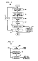
- Fig. 1 illustrates transmitter 100 for simulcasting digitally modulated signals and analog FM signals in accordance with the invention.
- FM modulator 101 which may reside in a FM radio station, in a standard way generates a stereo FM signal in response to an analog input signal.
- the FM signal is to be transmitted over a frequency band, which in this instance is 200 KHz wide, allocated to the FM broadcast.
- a frequency band which in this instance is 200 KHz wide, allocated to the FM broadcast.
- m(t) denote an analog modulating signal in FM modulation.
- the FM carrier f c after it is modulated by m(t) results in the following FM modulated signal x FM :
- x FM (t) cos [ ⁇ (t)], where ⁇ (t) represents the phase angle given by with the assumption that where f d represents the maximum frequency deviation.
- f d is typically 75 KHz
- m(t) is a stereo signal derived from left and right channel information signals represented by L(t) and R(t), respectively.
- L(t) and R(t) are processed by pre-emphasis filters to form L p (t) and R p (t), respectively.
- the rightmost term, a 3 cos(2 ⁇ f p t), in the above expression is referred to as a "Pilot Signal" with carrier frequency f p . It is used by FM receivers to coherently demodulate the passband term involving the difference between the left and right signals.
- a conventional FM receiver includes a device for deriving an angle signal from the received version of x FM (t).
- a mathematical derivative operation of this angle signal provides m ⁇ (t), an estimate of m(t).
- a lowpass filter is used to obtain an estimate of the [L p (t) + R p (t)].
- Stereo receivers use the pilot signal to demodulate [L p (t) - R p (t)], which is then linearly combined with the estimate of [L p (t) + R p (t)] to obtain L p ⁇ (t) and R p ⁇ (t), the estimates of L P (t) and R p (t), respectively.
- transmitter 100 is used to transmit a digitally modulated signal representing digital data, together with the host analog FM signal from modulator 101, over the same FM band.
- One of the objectives of the invention is to allow an FM receiver to process the host analog FM signal in a conventional manner and provide a virtually undeteriorated FM quality, despite the fact that the FM signal shares the same frequency band with the digitally modulated signals.
- the digitally modulated signal is inserted in the host FM band at a low enough power level to avoid causing significant co-channel interference at the FM receiver.
- Coverage of a digitally modulated signal with low transmission power is normally limited.
- the inventive technique improves such coverage.
- the inventive technique includes a precanceling scheme whereby interference which would otherwise be caused by the host analog FM signal to the digitally modulated signal is precanceled.
- the precanceling scheme cancellation or elimination of a calculated response of the analog FM signal from the digitally modulated signal is performed at transmitter 100. Since the waveform of the FM signal is a priori known at the transmitter, the precancellation is achievable by eliminating from the digitally modulated signal the would-be effect of the FM signal thereon before the simulcast. Thus, with the precanceling scheme, the digital data transmission, though sharing the same band with the analog FM transmission, is devoid of interference from the analog FM signal at the digital data receiver, subject only to the channel noise.
- digital data is transmitted pursuant to an adaptive orthogonal frequency division multiplexed scheme.
- digital data is input at multicarrier (or multitone) modem 103, which provides multiple carrier frequencies or tones for digital data transmission.
- the input digital data are channel coded and interleaved in a conventional manner to become more immune to the channel noise.
- the digital data transmission by multicarrier modem 103 is achieved using N pulse shaping tones or carriers, each occupying a subband having a bandwidth of 200/N KHz, where N is a predetermined integer having a value greater than 1.
- Modem 103 includes N pulse shaping filters, denoted 105-1 through 105-N, each associated with a different carrier.
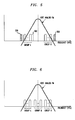
- Modem 103 transmits the data symbols on a frame-by-frame basis, with each frame containing M symbols, where M is a predetermined integer having a value greater than 0. Within each frame only a subset of carriers of modem 103 are used for digital data transmission. Fig. 2 shows such a subset populating the FM band during a particular frame. The frequencies and number of carriers in the subset may vary from frame to frame, and are selected in a manner to be described so that the degree of degradation caused by the digital data transmission to the host analog FM signal would be acceptable.
- the corresponding digitally modulated signal to be transmitted on the n-th carrier may be represented by d n (t) as follows: where h n (t) represents the impulse response of pulse shaping filter 105-n associated with the n-th carrier.
- the host analog FM signal represented by x FM (t)
- the analog signal and the delayed versions thereof would make a nonzero contribution to the received symbols.
- precanceler 107 constructs a canceling signal a n (t) for canceling beforehand all the would-be effects attributed to x FM (t) on d n (t) such that the digital receiver would in effect receive d n (t) only.
- a n (t) the output of the overall system (the channel plus digital receiver) attributed to a n (t) be denoted b n ⁇ [k], and the output of same attributed to x FM (t) be denoted c n ⁇ [k].
- Precanceler 107 seeks conditions on a n (t) such that Expression (1) represents a zero-forcing condition under which the analog FM signal causes zero interference to the transmission of the digitally modulated signal.
- precanceler 107 can construct a n (t) to meet condition (3) based only on the knowledge of h n (-t) and x FM (t).
- a n (f) must equal X FM (f) whenever the frequency response of the matched filter is nonzero.
- precanceler 107 Since the digitally modulated signal is transmitted by transmitter 100 which also transmits the host analog FM signal x FM (t), using the knowledge of the waveform of the FM signal, precanceler 107 is capable of computing a n (t) at the cost of a short delay. Using the computed results, precanceler 107 then precancels the effect that the FM signal would otherwise have on the digitally modulated signal when the two signals are simulcast over the same band. The precanceled digitally modulated signal at the output of precanceler 107 is represented by d n (t) + a n (t).
- the precanceled digitally modulated signal is applied to adder 109 where the precanceled signal is added to a delayed version of the host FM analog signal.
- the latter comes from the output of delay element 111 which injects into the analog FM signal a delay as long as that incurred by precanceler 107 in computing a n (t).
- delay element 111 injects into the analog FM signal a delay as long as that incurred by precanceler 107 in computing a n (t).
- other delays may be introduced into various components of transmitter 100 to better synchronize their operations, and should be apparent to a person skilled in the art implementing the invention as disclosed.
- a subset S of the N carriers in multicarrier modem 103 is selected.
- linear power amplifier 113 of conventional design.
- the latter transmits an amplified version of the composite signal x(t) over the allocated FM frequency band.
- the manner in which the subset S of the N carriers in modem 103 is selected for digital data transmission will now be described.
- the precanceling scheme described above guarantees that the digital data is transmitted without interference from the host analog FM signal.
- the host analog FM signal may be significantly affected by the digitally modulated signal using such a scheme.
- one of the objectives of the invention is to select as large a subset (S) of the carriers as possible while the total degradation incurred to the host analog FM signal is kept at an acceptable level.
- L ⁇ (t) and R ⁇ (t) can be predetermined whether they are of acceptable quality.
- the figure of merit (y) used in this particular embodiment is defined as follows:
- the subset (S) of carriers are selected by carrier insertion module 116 on a time-frame by time-frame basis.
- Module 116 runs an insertion algorithm to turn on as many carriers as possible during each frame, subject to a preselected constraint, ⁇ max , representing the maximum acceptable degradation to the host analog FM signal.
- module 116 selects the carriers in a predetermined order. In particular, they are selected in pairs. As shown in Fig. 2, carriers 201a and 201b, carriers 202a and 202b, carriers 203a and 203b, and carriers 204a and 204b are four such pairs. The members of each pair are separated and disposed symmetrically about center line C of the FM band.
- each pair is contiguous to the respective ones of the other pairs. That is, carriers 201a, 202a, 203a and 204a are disposed contiguously to one another and form group L while carriers 201b, 202b, 203b and 204b are disposed contiguously to one another and from group R.
- the order in which the pairs are selected for insertion is from the outermost pair of carriers close to the respective ends of the FM band to the innermost allowed pair of carriers close to center line C.
- the first pair selected for insertion in this instance is pair 201a and 201b which are the outermost pair-, presumably the least disturbing to the FM signal, followed by inner pairs --202a and 202b pair, 203a and 203b pair, and so on and so forth up to a limit in that order. Since each carrier occupies a subband of 200/N KHz, the maximum number of pairs to be selected (or number of members in group L or R) is N/2 if N is an even number, or (N - 1)/2 if N is an odd number. However, the actual number of pairs selected for insertion is determined by carrier insertion process 300.
- Fig. 3 is a flow chart depicting the steps of carrier insertion process 300 run by module 116 in accordance with the invention.
- Transmission of all carriers in the subset S together with the host analog FM signal is then emulated at step 304.
- the carriers contain random digital data in the emulated transmission.
- the carriers may contain the actual digital data to be transmitted in the emulation.
- module 116 performs an interference analysis of the emulated transmission, taking into account the precancellation effect of the subset of carriers on the FM signal. Based on the interference analysis, module 116 at step 307 computes the value of ⁇ aggregate indicative of the aggregate degradation caused by the subset of carriers to the FM signal. At step 311, module 116 determines whether the value of ⁇ aggregate exceeds that of ⁇ max . If ⁇ aggregate > ⁇ max , i.e., the aggregate degradation is greater than the maximum acceptable degradation, which is not allowed, process 300 is coming to an end. Specifically, before the process ends, the p-th carrier pair just added to the subset S is eliminated therefrom, as indicated at step 313.
- Control channel processor 119 is employed to generate data bits representing such control information, and causes the generated bits to be transmitted over control channel 206 in Fig. 2, which is reserved outside the analog signal spectrum.
- the data rate required to convey the control information is advantageously much lower (and thus less control channel bandwidth is needed) than that in the Papadopoulos and Sundberg scheme described above.
- N bits per frame are required to identify the on-off states of N carriers which may possibly be used.
- control information is needed to identify to the receiver only the innermost carrier pair that is used. From that information, the receiver readily derives all the carriers that were used in transmitter 100.
- Fig. 4 illustrates receiver 400 for receiving from the FM frequency band a composite signal x'(t) corresponding to x(t) and the control channel information generated at transmitter 100. Because of the precancellation performed at the transmitter, the design of receiver 400 is advantageously simple. As mentioned before, FM receiver 403 in receiver 400 is of conventional design and, in a standard way recovers the original analog signal. Synchronization control decoder 405 decodes the control channel information in x'(t) identifying the inner most carrier pair which was used for digital transmission in each transmission interval. Because of the above ordered selection of the carriers in accordance with the invention, decoder 405 readily derives from that information the identities of all the carriers that were used in transmitter 100, and such identities are then conveyed to demodulator 407. In response, demodulator 407 performs the inverse function to modulator 103 on x'(t) to recover therefrom the digital data, albeit channel-coded and interleaved.
- the frequency carriers are selected by carrier insertion module 116 for insertion into the FM band on a pair by pair basis.
- the invention broadly applies to other insertion schemes such as one in which the carriers are selected one at a time in a sequential order from the outermost carrier in the FM band to one or more inner carriers contiguous to one another.
- Another insertion scheme may require that the carriers are selected one at a time from group L and group R alternately.
- the last scheme may also be combined with disclosed insertion process 300 to yield a hybrid insertion process.
- a single carrier 502 contiguous to group L (group R) is inserted into the FM band to test the acceptable degradation limit. If the insertion does not violate the limit, carrier 502 is adopted and the hybrid process ends there. Otherwise, carrier 502 is similarly inserted contiguously to group R (group L) to test the acceptable degradation limit. If such an insertion does not violate the limit, carrier 502 is adopted. In any event, the hybrid process ends thereafter.
- control information identifying the inserted carriers is transmitted to the receiver over a discrete control channel, i.e., control channel 206.
- control channel 206 a discrete control channel
- protective measures may be taken to secure the communication of the control information.
- an additional control channel such as control channel 506 in Fig. 5, located at a different frequency than control channel 206, may be utilized to transmit the same control information as channel 206, for fear that one of the control channels may be adversely affected at times.
- the carriers are selected from two groups, namely, group R and group L. It will be appreciated that a person skilled in the art will select carriers from more than two groups such as groups R, L and Q as shown in Fig. 6. Alternatively, the carriers may also be selected from only one of those groups. In addition, it will be appreciated that a person skilled in the art will apply the inventive band insertion and precancellation technique with a variety of standard digital modulation techniques including, for example, MPSK and MQAM techniques.
- inventive band insertion and precancellation technique may be selectively applied. In certain situations, precancellation may not be necessary.
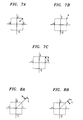
- a well-known QPSK constellation is used for generating data symbols.
- Figs. 7A through 7C respectively show three possible scenarios where we assume that the symbol transmitted was at 1 + j.
- the received symbol in the absence of noise is indicated by "x" inside the square whose corners are marked by the four possible symbols. Since the received symbol is closer to the decision boundaries than 1 + j which is the intended symbol, the effective SNR of this received symbol has been lowered. Precancellation in this case effectively moves the symbol in the direction of the dashed arrow to the position 1 + j to regain the desired SNR.
- the effective SNR of the received symbol without precanceling is higher than that of 1 + j. Since precancellation would reduce the SNR of the received symbol, and possibly introduce additional distortion to the host FM signal, we may want to refrain from applying precancellation in this case.
- the precancellation described above moves the received symbol in the direction of the dashed arrow to the position of 1 + j.
- such precancellation is inferior to the one that, for example, moves the received symbol in the direction of the solid arrow shown in Fig. 7C.
- the precancellation represented by the solid arrow further improves the SNR of the symbol, and possibly the host FM signal distortion.
- FIG. 8A and 8B an improved precanceling scheme is depicted here in Figs. 8A and 8B applying to the scenarios of Figs. 7B and 7C, respectively.
- the improved precancellation moves the received symbol "x" in the direction of the solid arrow perpendicularly to a solid line denoted L.
- Line L is an extension of the dashed line emanating from the origin of the constellation, and extends outwardly from the point 1 + j. Lines involving other symbols in the constellation can be formed in a similar manner.
- this improved precanceling scheme is applicable to digital transmission not only involving QPSK, but also other constellations, such as MPSK, MQAM, PAM, and multidimensional constellations.
- MPSK the improved precanceling scheme can be applied to all signal points therein, while in the case of MQAM, the improved precanceling scheme should be selectively applied to the outer signal points therein.
- a particular digitally modulated signal which is linearly modulated is simulcast with an analog FM signal which is non-linearly modulated
- the invention broadly applies to a simulcast of a linearly modulated signal with another linearly or non-linearly modulated signal.
- band insertion and precancellation technique described herein may be used in combination with other techniques such as the postcanceling technique disclosed in the co-pending, commonly assigned U.S. Patent Application Serial No. 08/748,043, filed on November 12, 1996, entitled “Technique for Simultaneous Communications of Analog Frequency-modulated and Digitally Modulated Signals using Postcanceling Scheme.”
Applications Claiming Priority (2)
| Application Number | Priority Date | Filing Date | Title |
|---|---|---|---|
| US08/834,541 US6075813A (en) | 1997-03-18 | 1997-03-18 | Band insertion and precancellation technique for simultaneous communication of analog frequency modulated and digitally modulated signals |
| US834541 | 1997-03-18 |
Publications (3)
| Publication Number | Publication Date |
|---|---|
| EP0866577A2 true EP0866577A2 (fr) | 1998-09-23 |
| EP0866577A3 EP0866577A3 (fr) | 2003-12-17 |
| EP0866577B1 EP0866577B1 (fr) | 2010-06-30 |
Family
ID=25267163
Family Applications (1)
| Application Number | Title | Priority Date | Filing Date |
|---|---|---|---|
| EP98301784A Expired - Lifetime EP0866577B1 (fr) | 1997-03-18 | 1998-03-11 | Insertion de bande et technique de préannulation pour communications simultanées des signaux anlogiques modulés en fréquence et des signaux modulés numériquement |
Country Status (5)
| Country | Link |
|---|---|
| US (2) | US6075813A (fr) |
| EP (1) | EP0866577B1 (fr) |
| JP (1) | JP3389492B2 (fr) |
| CA (1) | CA2228240C (fr) |
| DE (1) | DE69841744D1 (fr) |
Cited By (4)
| Publication number | Priority date | Publication date | Assignee | Title |
|---|---|---|---|---|
| EP0825736A2 (fr) * | 1996-08-22 | 1998-02-25 | Lucent Technologies Inc. | Communication simultanée des signaux analogique modulés en fréquence et des signaux modulés numériquement utilisant préannulation |
| WO2001052468A1 (fr) * | 2000-01-12 | 2001-07-19 | Ericson Inc. | Systèmes et procédés de communication sélectifs à multiporteuses, à séquence directe et spectre étalé |
| US7106689B1 (en) | 1999-03-02 | 2006-09-12 | Matsushita Electric Industrial Co., Ltd. | OFDM transmission/reception apparatus |
| WO2007101642A2 (fr) * | 2006-03-03 | 2007-09-13 | Micronas Gmbh | Signal radio à diffusion simultanée fm, système de transmission radio et dispositif récepteur pour ledit signal |
Families Citing this family (10)
| Publication number | Priority date | Publication date | Assignee | Title |
|---|---|---|---|---|
| US6259893B1 (en) * | 1998-11-03 | 2001-07-10 | Ibiquity Digital Corporation | Method and apparatus for reduction of FM interference for FM in-band on-channel digital audio broadcasting system |
| US6600908B1 (en) | 1999-02-04 | 2003-07-29 | Hark C. Chan | Method and system for broadcasting and receiving audio information and associated audio indexes |
| US7369824B1 (en) | 1999-02-04 | 2008-05-06 | Chan Hark C | Receiver storage system for audio program |
| US7245707B1 (en) | 1999-03-26 | 2007-07-17 | Chan Hark C | Data network based telephone messaging system |
| US6947748B2 (en) * | 2000-12-15 | 2005-09-20 | Adaptix, Inc. | OFDMA with adaptive subcarrier-cluster configuration and selective loading |
| US6798849B2 (en) | 2001-12-10 | 2004-09-28 | Ibiquity Digital Corporation | AM digital audio broadcasting with analog signal pre-compensation |
| EP1472867A1 (fr) * | 2002-01-11 | 2004-11-03 | Koninklijke Philips Electronics N.V. | Systeme de transmission |
| US7346125B2 (en) * | 2002-04-23 | 2008-03-18 | Raytheon Company | Method and device for pulse shaping QPSK signals |
| US7499501B2 (en) * | 2004-04-16 | 2009-03-03 | Omereen Wireless, Llc | Symbol error based compensation methods for nonlinear amplifier distortion |
| US7573851B2 (en) | 2004-12-07 | 2009-08-11 | Adaptix, Inc. | Method and system for switching antenna and channel assignments in broadband wireless networks |
Citations (4)
| Publication number | Priority date | Publication date | Assignee | Title |
|---|---|---|---|---|
| WO1994013506A1 (fr) * | 1992-12-17 | 1994-06-23 | United Technologies Automotive, Inc. | Ensemble de commutation pour siege d'automobile |
| JPH07297748A (ja) * | 1994-04-26 | 1995-11-10 | Clarion Co Ltd | 送受信方式 |
| US5499271A (en) * | 1991-04-11 | 1996-03-12 | Institut Fur Rundfunktechnik Gmbh | Method for broadcasting a digitally coded stream of data using an already occupied frequency spectrum |
| EP0825736A2 (fr) * | 1996-08-22 | 1998-02-25 | Lucent Technologies Inc. | Communication simultanée des signaux analogique modulés en fréquence et des signaux modulés numériquement utilisant préannulation |
Family Cites Families (7)
| Publication number | Priority date | Publication date | Assignee | Title |
|---|---|---|---|---|
| US5278826A (en) * | 1991-04-11 | 1994-01-11 | Usa Digital Radio | Method and apparatus for digital audio broadcasting and reception |
| US5315583A (en) * | 1991-04-11 | 1994-05-24 | Usa Digital Radio | Method and apparatus for digital audio broadcasting and reception |
| DE4306590A1 (de) * | 1992-09-21 | 1994-03-24 | Rohde & Schwarz | Digitales Rundfunk-Sendernetz-System |
| US5465396A (en) * | 1993-01-12 | 1995-11-07 | Usa Digital Radio Partners, L.P. | In-band on-channel digital broadcasting |
| US5588022A (en) * | 1994-03-07 | 1996-12-24 | Xetron Corp. | Method and apparatus for AM compatible digital broadcasting |
| US5956624A (en) * | 1994-07-12 | 1999-09-21 | Usa Digital Radio Partners Lp | Method and system for simultaneously broadcasting and receiving digital and analog signals |
| IL114471A0 (en) * | 1994-07-12 | 1996-01-31 | Usa Digital Radio Partners L P | Method and system for simultaneously broadcasting and analog signals |
-
1997
- 1997-03-18 US US08/834,541 patent/US6075813A/en not_active Expired - Lifetime
-
1998
- 1998-01-30 CA CA002228240A patent/CA2228240C/fr not_active Expired - Fee Related
- 1998-03-11 DE DE69841744T patent/DE69841744D1/de not_active Expired - Lifetime
- 1998-03-11 EP EP98301784A patent/EP0866577B1/fr not_active Expired - Lifetime
- 1998-03-16 JP JP06564698A patent/JP3389492B2/ja not_active Expired - Fee Related
-
2000
- 2000-02-09 US US09/501,383 patent/US6215815B1/en not_active Expired - Lifetime
Patent Citations (4)
| Publication number | Priority date | Publication date | Assignee | Title |
|---|---|---|---|---|
| US5499271A (en) * | 1991-04-11 | 1996-03-12 | Institut Fur Rundfunktechnik Gmbh | Method for broadcasting a digitally coded stream of data using an already occupied frequency spectrum |
| WO1994013506A1 (fr) * | 1992-12-17 | 1994-06-23 | United Technologies Automotive, Inc. | Ensemble de commutation pour siege d'automobile |
| JPH07297748A (ja) * | 1994-04-26 | 1995-11-10 | Clarion Co Ltd | 送受信方式 |
| EP0825736A2 (fr) * | 1996-08-22 | 1998-02-25 | Lucent Technologies Inc. | Communication simultanée des signaux analogique modulés en fréquence et des signaux modulés numériquement utilisant préannulation |
Non-Patent Citations (1)
| Title |
|---|
| PATENT ABSTRACTS OF JAPAN vol. 1996, no. 03, 29 March 1996 (1996-03-29) & JP 07 297748 A (CLARION CO LTD), 10 November 1995 (1995-11-10) * |
Cited By (12)
| Publication number | Priority date | Publication date | Assignee | Title |
|---|---|---|---|---|
| EP0825736A2 (fr) * | 1996-08-22 | 1998-02-25 | Lucent Technologies Inc. | Communication simultanée des signaux analogique modulés en fréquence et des signaux modulés numériquement utilisant préannulation |
| EP0825736A3 (fr) * | 1996-08-22 | 2001-03-07 | Lucent Technologies Inc. | Communication simultanée des signaux analogique modulés en fréquence et des signaux modulés numériquement utilisant préannulation |
| US7106689B1 (en) | 1999-03-02 | 2006-09-12 | Matsushita Electric Industrial Co., Ltd. | OFDM transmission/reception apparatus |
| EP1973257A1 (fr) * | 1999-03-02 | 2008-09-24 | Matsushita Electric Industrial Co., Ltd. | Appareil de transmission/réception OFDM |
| US7558190B2 (en) | 1999-03-02 | 2009-07-07 | Panasonic Corporation | OFDM transmission/reception apparatus |
| CN1832467B (zh) * | 1999-03-02 | 2012-01-04 | 松下电器产业株式会社 | 正交频分复用发送装置及方法、通信终端装置、基站装置 |
| US8179776B2 (en) | 1999-03-02 | 2012-05-15 | Panasonic Corporation | OFDM transmission/reception apparatus |
| WO2001052468A1 (fr) * | 2000-01-12 | 2001-07-19 | Ericson Inc. | Systèmes et procédés de communication sélectifs à multiporteuses, à séquence directe et spectre étalé |
| US6810070B1 (en) | 2000-01-12 | 2004-10-26 | Ericsson Inc. | Selective multi-carrier direct sequence spread spectrum communication systems and methods |
| WO2007101642A2 (fr) * | 2006-03-03 | 2007-09-13 | Micronas Gmbh | Signal radio à diffusion simultanée fm, système de transmission radio et dispositif récepteur pour ledit signal |
| WO2007101642A3 (fr) * | 2006-03-03 | 2008-07-03 | Micronas Gmbh | Signal radio à diffusion simultanée fm, système de transmission radio et dispositif récepteur pour ledit signal |
| US8095086B2 (en) | 2006-03-03 | 2012-01-10 | Trident Microsystems (Far East) Ltd. | FM simulcast broadcast signal broadcast transmission system and receiver device |
Also Published As
| Publication number | Publication date |
|---|---|
| CA2228240C (fr) | 2002-03-26 |
| EP0866577B1 (fr) | 2010-06-30 |
| US6075813A (en) | 2000-06-13 |
| JPH10271085A (ja) | 1998-10-09 |
| EP0866577A3 (fr) | 2003-12-17 |
| CA2228240A1 (fr) | 1998-09-18 |
| US6215815B1 (en) | 2001-04-10 |
| JP3389492B2 (ja) | 2003-03-24 |
| DE69841744D1 (de) | 2010-08-12 |
Similar Documents
| Publication | Publication Date | Title |
|---|---|---|
| US6144705A (en) | Technique for simultaneous communications of analog frequency-modulated and digitally modulated signals using precanceling scheme | |
| EP0839423B1 (fr) | Mise en forme d'impulsions pour la modulation de porteuses multiples | |
| US5914933A (en) | Clustered OFDM communication system | |
| EP0847643B1 (fr) | Procede de simplification de la demodulation dans des systemes a emetteurs multiporteuse | |
| US8630244B2 (en) | Channel structuring method and base station therewith | |
| EP0842568B1 (fr) | Dispositif adaptatif de desetalement de spectre | |
| US8107356B2 (en) | Method and apparatus for transmitting/receiving a signal in an FFH-OFDM communication system | |
| RU2248673C2 (ru) | Способ и устройство для определения режима передачи и синхронизации сигнала цифрового аудиовещания | |
| US6075813A (en) | Band insertion and precancellation technique for simultaneous communication of analog frequency modulated and digitally modulated signals | |
| EP1496659A1 (fr) | Dispositif et méthode pour la transmission et réception dans un système de communication MDFO avec une extension cyclique insuffisant | |
| US3935535A (en) | Fast equalization acquisition for automatic adaptive digital modem | |
| EP0872060A2 (fr) | Procede d'emission et de reception et systeme de radiodiffusion | |
| US20040258014A1 (en) | Apparatus and method for assigning a dedicated pilot channel for identification of a base station in an OFDM communication system | |
| KR20050105224A (ko) | 무선 데이터 전송 방법 및 그 신호, 시스템, 송신기 및수신기 | |
| EP0752177B1 (fr) | Systeme d'egalisation commune pour recepteur numerique compatible en modulation d'amplitude | |
| AU1565399A (en) | Upgrading of resources in a telecommunications network | |
| US7292640B2 (en) | System and method for an adaptive receiver for the reception of signals subject to multipath interference | |
| CN102142916A (zh) | 参考信号的复用方法及复用设备 | |
| US7346041B2 (en) | Processing of an OFDM signal | |
| EP1197026A1 (fr) | Procede et appareil pour l'estimation de voie, a diversite d'emission | |
| EP0122127A2 (fr) | Système de radio-communication | |
| JP2002261726A (ja) | Ofdm信号送受信装置 | |
| KR100964396B1 (ko) | 채널 추정, 등화 방법 및 시스템 | |
| KR100391565B1 (ko) | 수정된 싱크보간법을 이용한 레일리페이딩 보상방법 | |
| JP3514965B2 (ja) | 受信装置 |
Legal Events
| Date | Code | Title | Description |
|---|---|---|---|
| PUAI | Public reference made under article 153(3) epc to a published international application that has entered the european phase |
Free format text: ORIGINAL CODE: 0009012 |
|
| AK | Designated contracting states |
Kind code of ref document: A2 Designated state(s): AT BE CH DE DK ES FI FR GB GR IE IT LI LU MC NL PT SE |
|
| AX | Request for extension of the european patent |
Free format text: AL;LT;LV;MK;RO;SI |
|
| PUAL | Search report despatched |
Free format text: ORIGINAL CODE: 0009013 |
|
| AK | Designated contracting states |
Kind code of ref document: A3 Designated state(s): AT BE CH DE DK ES FI FR GB GR IE IT LI LU MC NL PT SE |
|
| AX | Request for extension of the european patent |
Extension state: AL LT LV MK RO SI |
|
| RIC1 | Information provided on ipc code assigned before grant |
Ipc: 7H 04H 1/00 B Ipc: 7H 04J 9/00 A |
|
| 17P | Request for examination filed |
Effective date: 20040219 |
|
| 17Q | First examination report despatched |
Effective date: 20040325 |
|
| AKX | Designation fees paid |
Designated state(s): DE FR GB |
|
| RAP3 | Party data changed (applicant data changed or rights of an application transferred) |
Owner name: LUCENT TECHNOLOGIES INC. |
|
| APBK | Appeal reference recorded |
Free format text: ORIGINAL CODE: EPIDOSNREFNE |
|
| APBN | Date of receipt of notice of appeal recorded |
Free format text: ORIGINAL CODE: EPIDOSNNOA2E |
|
| APBR | Date of receipt of statement of grounds of appeal recorded |
Free format text: ORIGINAL CODE: EPIDOSNNOA3E |
|
| APBV | Interlocutory revision of appeal recorded |
Free format text: ORIGINAL CODE: EPIDOSNIRAPE |
|
| GRAP | Despatch of communication of intention to grant a patent |
Free format text: ORIGINAL CODE: EPIDOSNIGR1 |
|
| RIC1 | Information provided on ipc code assigned before grant |
Ipc: H04H 20/31 20080101AFI20091203BHEP |
|
| GRAS | Grant fee paid |
Free format text: ORIGINAL CODE: EPIDOSNIGR3 |
|
| GRAA | (expected) grant |
Free format text: ORIGINAL CODE: 0009210 |
|
| AK | Designated contracting states |
Kind code of ref document: B1 Designated state(s): DE FR GB |
|
| REG | Reference to a national code |
Ref country code: GB Ref legal event code: FG4D |
|
| REF | Corresponds to: |
Ref document number: 69841744 Country of ref document: DE Date of ref document: 20100812 Kind code of ref document: P |
|
| PLBE | No opposition filed within time limit |
Free format text: ORIGINAL CODE: 0009261 |
|
| STAA | Information on the status of an ep patent application or granted ep patent |
Free format text: STATUS: NO OPPOSITION FILED WITHIN TIME LIMIT |
|
| 26N | No opposition filed |
Effective date: 20110331 |
|
| REG | Reference to a national code |
Ref country code: DE Ref legal event code: R097 Ref document number: 69841744 Country of ref document: DE Effective date: 20110330 |
|
| PGFP | Annual fee paid to national office [announced via postgrant information from national office to epo] |
Ref country code: FR Payment date: 20140311 Year of fee payment: 17 |
|
| PGFP | Annual fee paid to national office [announced via postgrant information from national office to epo] |
Ref country code: GB Payment date: 20140305 Year of fee payment: 17 |
|
| PGFP | Annual fee paid to national office [announced via postgrant information from national office to epo] |
Ref country code: DE Payment date: 20140417 Year of fee payment: 17 |
|
| REG | Reference to a national code |
Ref country code: DE Ref legal event code: R119 Ref document number: 69841744 Country of ref document: DE |
|
| GBPC | Gb: european patent ceased through non-payment of renewal fee |
Effective date: 20150311 |
|
| REG | Reference to a national code |
Ref country code: FR Ref legal event code: ST Effective date: 20151130 |
|
| PG25 | Lapsed in a contracting state [announced via postgrant information from national office to epo] |
Ref country code: GB Free format text: LAPSE BECAUSE OF NON-PAYMENT OF DUE FEES Effective date: 20150311 Ref country code: DE Free format text: LAPSE BECAUSE OF NON-PAYMENT OF DUE FEES Effective date: 20151001 |
|
| PG25 | Lapsed in a contracting state [announced via postgrant information from national office to epo] |
Ref country code: FR Free format text: LAPSE BECAUSE OF NON-PAYMENT OF DUE FEES Effective date: 20150331 |