EP0866247B1 - Radial shaft seal - Google Patents
Radial shaft seal Download PDFInfo
- Publication number
- EP0866247B1 EP0866247B1 EP97118666A EP97118666A EP0866247B1 EP 0866247 B1 EP0866247 B1 EP 0866247B1 EP 97118666 A EP97118666 A EP 97118666A EP 97118666 A EP97118666 A EP 97118666A EP 0866247 B1 EP0866247 B1 EP 0866247B1
- Authority
- EP
- European Patent Office
- Prior art keywords
- seal
- radial shaft
- radial
- housing
- shaft seal
- Prior art date
- Legal status (The legal status is an assumption and is not a legal conclusion. Google has not performed a legal analysis and makes no representation as to the accuracy of the status listed.)
- Expired - Lifetime
Links
Images
Classifications
-
- F—MECHANICAL ENGINEERING; LIGHTING; HEATING; WEAPONS; BLASTING
- F16—ENGINEERING ELEMENTS AND UNITS; GENERAL MEASURES FOR PRODUCING AND MAINTAINING EFFECTIVE FUNCTIONING OF MACHINES OR INSTALLATIONS; THERMAL INSULATION IN GENERAL
- F16J—PISTONS; CYLINDERS; SEALINGS
- F16J15/00—Sealings
- F16J15/16—Sealings between relatively-moving surfaces
- F16J15/32—Sealings between relatively-moving surfaces with elastic sealings, e.g. O-rings
- F16J15/3268—Mounting of sealing rings
- F16J15/3276—Mounting of sealing rings with additional static sealing between the sealing, or its casing or support, and the surface on which it is mounted
-
- F—MECHANICAL ENGINEERING; LIGHTING; HEATING; WEAPONS; BLASTING
- F16—ENGINEERING ELEMENTS AND UNITS; GENERAL MEASURES FOR PRODUCING AND MAINTAINING EFFECTIVE FUNCTIONING OF MACHINES OR INSTALLATIONS; THERMAL INSULATION IN GENERAL
- F16J—PISTONS; CYLINDERS; SEALINGS
- F16J15/00—Sealings
- F16J15/16—Sealings between relatively-moving surfaces
- F16J15/32—Sealings between relatively-moving surfaces with elastic sealings, e.g. O-rings
- F16J15/3204—Sealings between relatively-moving surfaces with elastic sealings, e.g. O-rings with at least one lip
- F16J15/3232—Sealings between relatively-moving surfaces with elastic sealings, e.g. O-rings with at least one lip having two or more lips
- F16J15/3236—Sealings between relatively-moving surfaces with elastic sealings, e.g. O-rings with at least one lip having two or more lips with at least one lip for each surface, e.g. U-cup packings
Definitions
- the invention relates to a radial shaft seal with at least one dynamically stressed first seal and at least one statically stressed second seal according to the preamble of claim 1.
- a radial shaft sealing ring is known, which is in a Guide sleeve for a clutch release bearing of a transmission is integrated. in this connection the two seals are adjustable and merge into one another Support ring set.
- On the clutch guide sleeve is radially on the outside Axial projection provided which the statically stressed second seal completely covered. Protection of the statically stressed second seal for example, before mechanical overloads is from Design of the axial projection of the clutch guide sleeve depending.
- the invention has for its object a Radiatwellendichtring the Provide generic type, which one of the receiving housing Independent support of the statically stressed seal with as much as possible low manufacturing costs and largely protected against stripping allowed by the support ring.
- the support ring has one Axial projection, which is the second seal to limit its elastic Deformation at least partially covered and on a housing to be sealed can be created.
- the advantage here is that the support ring on which the first and the second seal are set, the axial projection to protect the second Has seal.
- the second is independent of the design of the housing The seal is protected against external influences and mechanical overload.
- the support ring has a substantially S-shaped cross section, and the Centering seat is formed by the outer peripheral surface of the axial web, which the Radial webs of the support ring connects. Such a support ring can be Manufacture easily and inexpensively from a deep-drawn sheet.
- the undulation extending in the radial direction prevents a detachment of the side of the second seal facing the housing the same from the support ring, since the second seal can thereby escape and this results in excessive bending and shear stresses on the second Have the seal avoided.
- the support ring advantageously consists of a tough, hard material.
- the advantage here is that it is a non-creeping material that covers the housing its centering seat always the same throughout the entire service life Position is assigned.
- the use of a support ring made of metallic Material is also in terms of an inexpensive to manufacture Radial shaft seals of particular advantage.
- metallic materials different materials for the support ring are also conceivable. For example, polymeric materials can be used if they very little relaxation during a long period of use under load exhibit.
- the first and the second seal can be made of different, separate elastomer materials molded onto the support ring.
- the different materials of the two seals can be optimally adapted to the respective application.
- a simplified manufacture of the radial shaft seal can the first and the second seal consist of a matching elastomer material.
- the second seal can have a substantially rectangular cross section have and with the inner circumference of the axial projection and the sealing side facing the radially outer radial web adhesive be connected.
- the two seals are preferred with the support ring vulcanized. With such a configuration, the second seal is from Support ring completely enclosed on the side facing away from the housing and therefore excellently protected against external influences.
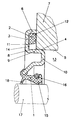
- FIG. 1 An exemplary embodiment of a radial shaft sealing ring is shown in the figure, with its centering seat 4 in the housing bore 5 of the housing 7 is pressed.
- the radial shaft seal has a dynamic load first seal 1 and a statically stressed second seal, the first seal 1 has a sealing lip 15, which is by an annular coil spring 16 is pressed in the radial direction on the shaft 17 to be sealed and this seals under radial preload.
- a face seal 18 is the side of the sealing lip 15 facing away from the space 13 arranged, which integrally merging into one another and using the same material the sealing lip 15 is formed and a component of the first seal 1 forms.
- the second seal 2 is on the side facing the housing 7 a corrugation extending in the radial direction, the Elevations and those adjacent on both sides in the radial direction Recesses are each annular in the circumferential direction.
- the support ring 3 is provided with an axial projection 6 which in the assembled state of the radial sealing ring touches the housing 7.
- the axial projection 6 protects the second seal 2 from mechanical, external Influences and an impermissibly high pressure load in the axial Direction during and after the installation of the radial shaft seal on the housing 7.
- the axial projection 6 bears against the housing 7 and prevents an even longer, unnecessarily long, the service life of the second seal 2 reducing deformation.
- the second seal 2 seals the medium to be sealed therefore has a very long service life flawlessly.
- the support ring 3 consists of a partially pullable sheet and has an essentially S-shaped Cross section on.
- the centering seat 4 is through the outer peripheral surface 8 of the Axial web 9 formed, the axial web 9, the two radial webs 10, 11 of the Support ring 3 connects together.
- the second seal 2 is on the inner circumference 12 of the axial projection 6 and with the space 13 to be sealed facing side 14 of the radially outer radial web 11 by vulcanization connected.
Abstract
Description
Die Erfindung befaßt sich mit einem Radialwellendichtring mit zumindest einer
dynamisch beanspruchten ersten Dichtung und zumindest einer statisch beanspruchten
zweiten Dichtung gemäß dem Oberbegriff des Patentanspruchs 1.The invention relates to a radial shaft seal with at least one
dynamically stressed first seal and at least one statically stressed
second seal according to the preamble of
Aus DE 296 03 159 U ist ein Verschlußdeckel bekannt, welcher insbesondere für Motor- und Getriebegehäuse bei Kraftfahrzeugen bestimmt ist. Durch diesen Verschlußdeckel geht eine Welle, welche mittels einer ersten dynamisch beanspruchten Dichtung abgedichtet wird. Gegenüber dem ortsfesten Gehäuse weist der Verschlußdeckel eine statisch beanspruchte zweite Dichtung auf. Beide Dichtungen sind über ein vom Verschlußdeckel gebildetes Stützringteil verbunden. Somit ist die Auslegung dieses Radialdichtrings von der Ausgestaltung des Gehäuses abhängig, und bei der statisch beanspruchten Dichtung kann es bei der Montage und auch im Funktionseinsatz zu Überbeanspruchungen hinsichtlich Biege- und Schubbelastungen mit der Folge einer Ablösung der statisch beanspruchten Dichtung vom Stützringteil kommen.From DE 296 03 159 U a closure cover is known, which is particularly suitable for Engine and transmission housing in motor vehicles is determined. Through this Closure cap goes a wave, which dynamic by means of a first claimed seal is sealed. Opposite the stationary housing the closure cover has a statically stressed second seal. Both Seals are connected via a support ring part formed by the cover. Thus, the design of this radial sealing ring is different from the design of the Depending on the housing, and with the statically stressed seal, it can with Assembly and also in functional use to overstress with regard Bending and shear loads with the consequence of a detachment of the statically stressed The seal comes from the support ring part.
Aus EP 0 579 869 B1 ist ein Radialwellendichtring bekannt, welcher in eine Führungshülse für ein Kupplungsausrücklager eines Getriebes integriert ist. Hierbei sind die beiden Dichtungen einstellbar ineinander übergehend ausgebildet und am Stützring festgelegt. An der Kupplungsführungshülse ist radial außenseitig ein Axialvorsprung vorgesehen, welcher die statisch beanspruchte zweite Dichtung vollständig überdeckt. Der Schutz der statisch beanspruchten zweiten Dichtung beispielsweise vor mechanischen Überbeanspruchungen ist aber von der Ausgestaltung des Axialvorsprungs der Kupplungsführungshülse abhängig. From EP 0 579 869 B1 a radial shaft sealing ring is known, which is in a Guide sleeve for a clutch release bearing of a transmission is integrated. in this connection the two seals are adjustable and merge into one another Support ring set. On the clutch guide sleeve is radially on the outside Axial projection provided which the statically stressed second seal completely covered. Protection of the statically stressed second seal for example, before mechanical overloads is from Design of the axial projection of the clutch guide sleeve depending.
Der Erfindung liegt die Aufgabe zugrunde, einen Radiatwellendichtring der gattungsgemäßen Art bereitzustellen, welcher eine vom Aufnahmegehäuse unabhängige Abstützung der statisch beanspruchten Dichtung mit möglichst günstigen Herstellungskosten und weitgehend geschützt vor Ablösebeanspruchungen vom Stützring gestattet.The invention has for its object a Radiatwellendichtring the Provide generic type, which one of the receiving housing Independent support of the statically stressed seal with as much as possible low manufacturing costs and largely protected against stripping allowed by the support ring.
Nach der Erfindung wird hierzu ein Radialwellendichtring bereitgestellt, dessen
Merkmale im Patentanspruch 1 angegeben sind.According to the invention, a radial shaft seal is provided for this purpose
Features are specified in
Bevorzugte Weiterbildungen der Erfindung sind in den Ansprüchen 2 bis 5
wiedergegeben.Preferred developments of the invention are in
Bei dem erfindungsgemäßen Radialwellendichtring hat der Stützring einen Axialvorsprung, der die zweite Dichtung zur Begrenzung ihrer elastischen Verformung zumindest teilweise überdeckt und an ein abzudichtendes Gehäuse anlegbar ist. Hierbei ist von Vorteil, daß der Stützring, an dem die erste und die zweite Dichtung festgelegt sind, den Axialvorsprung zum Schutz der zweiten Dichtung aufweist. Unabhängig von der Ausgestaltung des Gehäuses ist die zweite Dichtung vor äußeren Einflüssen und vor mechanischen Überbelastung geschützt. Der Stützring weist einen im wesentlichen S-förmigen Querschnitt auf, und der Zentriersitz wird durch die Außenumfangsfläche des Axialstegs gebildet, der die Radialstege des Stützrings verbindet. Ein derart ausgebildeter Stützring läßt sich problemlos und kostengünstig aus einem tiefziehbaren Blech herstellen. Einer zusätzlichen, arbeits- und kostenintensiven Bearbeitung des Zentriersitzes bedarf es nicht. Ferner verhindert die sich in radialer Richtung erstreckende Wellung an der dem Gehäuse zugewandten Seite der zweiten Dichtung eine Ablösung derselben vom Stützring, da die zweite Dichtung hierdurch ausweichen kann und sich hierdurch zu starke Biege- und Schubbeanspruchungen an der zweiten Dichtung vermeiden lassen.In the case of the radial shaft sealing ring according to the invention, the support ring has one Axial projection, which is the second seal to limit its elastic Deformation at least partially covered and on a housing to be sealed can be created. The advantage here is that the support ring on which the first and the second seal are set, the axial projection to protect the second Has seal. The second is independent of the design of the housing The seal is protected against external influences and mechanical overload. The support ring has a substantially S-shaped cross section, and the Centering seat is formed by the outer peripheral surface of the axial web, which the Radial webs of the support ring connects. Such a support ring can be Manufacture easily and inexpensively from a deep-drawn sheet. one additional, labor-intensive and cost-intensive machining of the centering seat is required it not. Furthermore, the undulation extending in the radial direction prevents a detachment of the side of the second seal facing the housing the same from the support ring, since the second seal can thereby escape and this results in excessive bending and shear stresses on the second Have the seal avoided.
Vorteilhafterweise besteht der Stützring aus einem zähharten Werkstoff. Bevorzugt besteht der Stützing aus einem tiefziehbaren Blech. Hierbei ist von Vorteil, daß es sich dabei um einen nichtkriechenden Werkstoff handelt, der dem Gehäuse über seinen Zentriersitz während der gesamten Gebrauchsdauer in stets gleicher Position zugeordnet ist. Die Verwendung eines Stützrings aus metallischem Werkstoff ist außerdem im Hinblick auf eine kostengünstige Herstellbarkeit des Radialwellendichtrings von hervorzuhebendem Vorteil. Von metallischen Werkstoffen abweichende Werkstoffe für den Stützring sind ebenfalls denkbar. Beispielsweise können polymere Werkstoffe zur Anwendung gelangen, sofern sie während einer langen Gebrauchsdauer unter Last nur eine sehr geringe Relaxation aufweisen.The support ring advantageously consists of a tough, hard material. Prefers the support consists of a deep-drawn sheet. The advantage here is that it is a non-creeping material that covers the housing its centering seat always the same throughout the entire service life Position is assigned. The use of a support ring made of metallic Material is also in terms of an inexpensive to manufacture Radial shaft seals of particular advantage. Of metallic materials different materials for the support ring are also conceivable. For example, polymeric materials can be used if they very little relaxation during a long period of use under load exhibit.
Die erste und die zweite Dichtung können aus voneinander abweichenden, separat an den Stützring angespritzten Elastomerwerkstoffen bestehen. Hierbei ist von Vorteil, daß die voneinander abweichenden Werkstoffe der beiden Dichtungen an den jeweiligen Anwendungsfall optimal angepaßt werden können. Im Hinblick auf eine vereinfachte Herstellbarkeit des Radialwellendichtrings können die erste und die zweite Dichtung aus einem übereinstimmenden Elastomerwerkstoff bestehen.The first and the second seal can be made of different, separate elastomer materials molded onto the support ring. Here is from Advantage that the different materials of the two seals can be optimally adapted to the respective application. With regard A simplified manufacture of the radial shaft seal can the first and the second seal consist of a matching elastomer material.
Im Hinblick auf eine vereinfachte Herstellbarkeit des Radialwellendichtrings besteht auch die Möglichkeit, daß die beiden Dichtungen aus einem übereinstimmenden Elastomerwerkstoff bestehen und beispielsweise einstückig ineinander übergehend ausgebildet sind.With regard to a simplified manufacturability of the radial shaft sealing ring also the possibility that the two seals from a matching Elastomer material exist and merge into one another, for example are trained.
Die zweite Dichtung kann einen im wesentlichen rechteckigen Querschnitt aufweisen und mit dem Innenumfang des Axialvorsprungs sowie der dem abzudichtenden Raum zugewandten Seite des radial äußeren Radialstegs adhäsiv verbunden sein. Die beiden Dichtungen sind bevorzugt mit dem Stützring vulkanisiert. Durch eine derartige Ausgestaltung ist die zweite Dichtung vom Stützring auf der dem Gehäuse abgewandten Seite vollständig umschlossen und daher vor äußeren Einflüssen ausgezeichnet geschützt.The second seal can have a substantially rectangular cross section have and with the inner circumference of the axial projection and the sealing side facing the radially outer radial web adhesive be connected. The two seals are preferred with the support ring vulcanized. With such a configuration, the second seal is from Support ring completely enclosed on the side facing away from the housing and therefore excellently protected against external influences.
Ein Ausführungsbeispiel wird nachfolgend anhand der Zeichnung näher erläutert. Diese zeigt die zu berücksichtigenden Einzelkomponenten teilweise in schematischer Darstellung. An embodiment is explained below with reference to the drawing. This shows the individual components to be taken into account partly in a schematic manner Presentation.
In der Figur ist ein Ausführungsbeispiel eines Radialwellendichtringes gezeigt,
der mit seinem Zentriersitz 4 in die Gehäusebohrung 5 des Gehäuses 7
eingepreßt ist. Der Radialwellendichtring weist eine dynamisch beanspruchte
erste Dichtung 1 und eine statisch beanspruchte zweite Dichtung auf, wobei die
erste Dichtung 1 eine Dichtlippe 15 aufweist, die durch eine Ringwendelfeder
16 in radialer Richtung an die abzudichtende Welle 17 angepreßt ist und diese
unter radialer Vorspannung dichtend umschließt. Auf der dem abzudichtenden
Raum 13 abgewandten Seite der Dichtlippe 15 ist eine Vorschaltdichtung 18
angeordnet, die einstückig ineinander übergehend und materialeinheitlich mit
der Dichtlippe 15 ausgebildet ist und einen Bestandteil der ersten Dichtung 1
bildet. Die zweite Dichtung 2 ist auf der dem Gehäuse 7 zugewandten Seite mit
einer sich in radialer Richtung erstreckenden Wellung versehen, wobei die
Erhebungen und die in radialer Richtung beiderseits angrenzenden
Vertiefungen jeweils in Umfangsrichtung ringförmig ausgebildet sind.
Bei einer derartigen Ausgestaltung ist von Vorteil, daß der imkompressible
elastomere Werkstoff bei seiner Verformung in die Vertiefungen auszuweichen
vermag und daher Biege-/Schubbeanspruchungen, die zu einer Ablösung der
zweiten Dichtung 2 vom Schutzring 3 führen könnten, vermieden wird.An exemplary embodiment of a radial shaft sealing ring is shown in the figure,
with its centering
Radial außenseitig ist der Stützring 3 mit einem Axialvorsprung 6 versehen, der
im montierten Zustand des Radialdichtrings das Gehäuse 7 anliegend berührt.
Der Axialvorsprung 6 schützt die zweite Dichtung 2 vor mechanischen, äußeren
Einflüssen und einer unzulässig hohen Druckbeanspruchung in axialer
Richtung während und im Anschluß an die Montage des Radialwellendichtrings
am Gehäuse 7. Bei einer vorherbestimmten, elastischen Vorspannung der
zweiten Dichtung 2 legt sich der Axialvorsprung 6 an das Gehäuse 7 an und
verhindert dadurch eine noch größere, unnötig hohe, die Gebrauchsdauer der
zweiten Dichtung 2 reduzierende Verformung. Die zweite Dichtung 2 dichtet
das abzudichtende Medium daher während einer sehr langen Gebrauchsdauer
einwandfrei ab. In diesem Ausführungsbeispiel besteht der Stützring 3 aus
einem teilziehbaren Blech und weist einen im wesentlichen S-förmigen
Querschnitt auf. Der Zentriersitz 4 ist durch die Außenumfangsfläche 8 des
Axialstegs 9 gebildet, wobei der Axialsteg 9 die beiden Radialstege 10, 11 des
Stützrings 3 miteinander verbindet. Die zweite Dichtung 2 ist am Innenumfang
12 des Axialvorsprungs 6 sowie mit der dem abzudichtenden Raum 13
zugewandten Seite 14 des radial äußeren Radialstegs 11 durch Vulkanisation
verbunden.Radially on the outside, the
Claims (5)
- A radial shaft seal with at least one dynamically loaded first seal (1) and at least one statically loaded second seal (2), the seals being connected to a supporting ring (3) which can be secured in a housing bore (5) by way of a centring seat (4), has an essentially S-shaped cross section and an axial protrusion (6), which at least partially covers over the second seal (2), in order to limit the elastic deformation thereof, and can be positioned against a housing (7) which is to be sealed, characterized in that the centring seat (4) is formed by an outer circumferential surface (8) of an axial web (9) which connects the radial webs (10, 11) of the supporting ring (3), and the second seal (2) is provided, on a side (12) which is directed towards the housing (7), with a radially directed corrugation.
- A radial shaft seal according to claim 1, characterized in that the radially extending corrugation comprises elevations and radially adjacent depressions, of annular design in the circumferential direction in each case.
- A radial shaft seal according to claim 1 or 2, characterized in that the supporting ring (3) consists of a hard and tough material.
- A radial shaft seal according to any one of claims 1 to 3, characterized in that the first seal (1) and the second seal (2) consist of different elastomer materials which are injection moulded separately onto the supporting ring (3).
- A radial shaft seal according to any one of claims 1 to 4, characterized in that the second seal (2) has an essentially rectangular cross section and is abhesively connected to the inner circumference (12) of the axial protrusion (6) and the side (14) of the radially outer radial web (11), said side being directed towards the space (13) which is to be sealed.
Applications Claiming Priority (2)
| Application Number | Priority Date | Filing Date | Title |
|---|---|---|---|
| DE19711400 | 1997-03-19 | ||
| DE19711400A DE19711400C2 (en) | 1997-03-19 | 1997-03-19 | Radial shaft seal |
Publications (3)
| Publication Number | Publication Date |
|---|---|
| EP0866247A2 EP0866247A2 (en) | 1998-09-23 |
| EP0866247A3 EP0866247A3 (en) | 1999-08-04 |
| EP0866247B1 true EP0866247B1 (en) | 2003-04-23 |
Family
ID=7823869
Family Applications (1)
| Application Number | Title | Priority Date | Filing Date |
|---|---|---|---|
| EP97118666A Expired - Lifetime EP0866247B1 (en) | 1997-03-19 | 1997-10-28 | Radial shaft seal |
Country Status (7)
| Country | Link |
|---|---|
| US (1) | US6062571A (en) |
| EP (1) | EP0866247B1 (en) |
| CN (1) | CN1107827C (en) |
| AT (1) | ATE238510T1 (en) |
| BR (1) | BR9800923A (en) |
| DE (2) | DE19711400C2 (en) |
| ES (1) | ES2194143T3 (en) |
Families Citing this family (6)
| Publication number | Priority date | Publication date | Assignee | Title |
|---|---|---|---|---|
| US6634648B1 (en) * | 2000-06-29 | 2003-10-21 | Kelsey-Hayes Company | Shield and seal assembly for vehicle wheel end assembly |
| DE10235079A1 (en) * | 2002-07-31 | 2004-02-19 | Carl Freudenberg Kg | cup seal |
| EP2211076B1 (en) * | 2009-01-21 | 2015-09-02 | Carl Freudenberg KG | Seal |
| JP5311649B2 (en) * | 2009-03-30 | 2013-10-09 | 内山工業株式会社 | Annular sealing device |
| DE102010001345B4 (en) * | 2010-01-28 | 2013-09-19 | Trelleborg Sealing Solutions Germany Gmbh | Rotary union |
| US11084551B1 (en) | 2020-04-22 | 2021-08-10 | Peter Stull | Foldable recumbent tricycle frame |
Citations (1)
| Publication number | Priority date | Publication date | Assignee | Title |
|---|---|---|---|---|
| DE3038717A1 (en) * | 1979-09-25 | 1982-05-27 | Polimac S.a.s. di Pelissero-Panchetti & C., 10151 Torino | RADIAL SEAL |
Family Cites Families (15)
| Publication number | Priority date | Publication date | Assignee | Title |
|---|---|---|---|---|
| US2105871A (en) * | 1936-03-20 | 1938-01-18 | Nat Bearing Metals Corp | Oil and dust seal for journal boxes |
| US3843139A (en) * | 1970-12-23 | 1974-10-22 | Garlock Inc | Oil seal |
| US4156531A (en) * | 1976-10-04 | 1979-05-29 | Esco Transmissions | Sealing ring for flexible toothed coupling and couplings provided with such rings |
| DE2653457C3 (en) * | 1976-11-25 | 1980-09-11 | Goetze Ag, 5093 Burscheid | Lip seal ring |
| FR2452633A1 (en) * | 1979-03-29 | 1980-10-24 | Skf Cie Applic Mecanique | ELASTIC SELF-ALIGNING CLUTCH WITH A COMPOSITE GUIDE SOCKET |
| JPH067220Y2 (en) * | 1986-08-13 | 1994-02-23 | 株式会社共立 | Oil seal |
| DE3634735A1 (en) * | 1986-10-11 | 1988-04-21 | Goetze Ag | LOCKING CAP, ESPECIALLY FOR CRANKSHAFT AND GEARBOX HOUSING IN MOTOR VEHICLES |
| US5018750A (en) * | 1989-06-02 | 1991-05-28 | Deere & Company | Shaft seal assembly |
| DE4123688A1 (en) * | 1991-07-17 | 1993-01-21 | Goetze Ag | SHAFT SEAL |
| FR2682441B1 (en) * | 1991-10-15 | 1993-12-10 | Procal | GUIDE TUBE WITH BUILT-IN SEAL FOR MOTOR VEHICLE GEARBOX CLUTCH. |
| US5167419A (en) * | 1991-10-22 | 1992-12-01 | Freudenberg-Nok General Partnership | Fluid seal with integral check valve |
| DE4224179C1 (en) | 1992-07-22 | 1993-11-11 | Freudenberg Carl Fa | Guide sleeve with integrated seal for a clutch release bearing of a transmission |
| DE9303000U1 (en) * | 1993-03-02 | 1993-04-22 | Goetze Ag, 5093 Burscheid, De | |
| DE29603159U1 (en) * | 1996-02-22 | 1996-05-02 | Cr Elastomere Gmbh | Closure cover, in particular for engine and gearbox housings in motor vehicles |
| FR2745618B1 (en) * | 1996-02-29 | 1999-01-08 | Valeo | CLUTCH DEVICE FOR A MOTOR VEHICLE CLUTCH COMPRISING AN IMPROVED ROTATING SHAFT SEAL |
-
1997
- 1997-03-19 DE DE19711400A patent/DE19711400C2/en not_active Expired - Lifetime
- 1997-10-28 AT AT97118666T patent/ATE238510T1/en not_active IP Right Cessation
- 1997-10-28 EP EP97118666A patent/EP0866247B1/en not_active Expired - Lifetime
- 1997-10-28 DE DE59709910T patent/DE59709910D1/en not_active Expired - Lifetime
- 1997-10-28 ES ES97118666T patent/ES2194143T3/en not_active Expired - Lifetime
-
1998
- 1998-01-09 US US09/004,840 patent/US6062571A/en not_active Expired - Fee Related
- 1998-03-17 BR BR9800923-0A patent/BR9800923A/en not_active IP Right Cessation
- 1998-03-17 CN CN98105709A patent/CN1107827C/en not_active Expired - Fee Related
Patent Citations (1)
| Publication number | Priority date | Publication date | Assignee | Title |
|---|---|---|---|---|
| DE3038717A1 (en) * | 1979-09-25 | 1982-05-27 | Polimac S.a.s. di Pelissero-Panchetti & C., 10151 Torino | RADIAL SEAL |
Also Published As
| Publication number | Publication date |
|---|---|
| CN1107827C (en) | 2003-05-07 |
| BR9800923A (en) | 1999-09-21 |
| ES2194143T3 (en) | 2003-11-16 |
| EP0866247A3 (en) | 1999-08-04 |
| DE19711400C2 (en) | 2001-12-06 |
| CN1193702A (en) | 1998-09-23 |
| US6062571A (en) | 2000-05-16 |
| EP0866247A2 (en) | 1998-09-23 |
| ATE238510T1 (en) | 2003-05-15 |
| DE59709910D1 (en) | 2003-05-28 |
| DE19711400A1 (en) | 1998-10-01 |
Similar Documents
| Publication | Publication Date | Title |
|---|---|---|
| EP0382197A1 (en) | Clutch disc | |
| DE3242448A1 (en) | PULLEY OF A CONTINUOUSLY REGULATED GEARBOX | |
| EP1612448A1 (en) | Elastomeric bush with improved torsion charateristics | |
| EP0472828B1 (en) | Bearing for a gear shift lever | |
| EP1026428A2 (en) | Sealing ring | |
| EP0866247B1 (en) | Radial shaft seal | |
| EP2827026B1 (en) | Sealing assembly and sealing ring | |
| WO2015022144A1 (en) | Sealing ring | |
| EP0829663B1 (en) | Mechanical face seal | |
| DE3832543A1 (en) | Bearing for the elastic support of a shaft, especially a centre bearing for the prop shaft of a vehicle drive | |
| DE2939560A1 (en) | Bearing cap for small machine ball race - giving firm location without requiring close dimensional tolerances for bearing housing | |
| DE19754400C2 (en) | Cassette seal | |
| EP1323958B1 (en) | Seal | |
| EP0565771B1 (en) | Hub seal | |
| WO2001031211A1 (en) | Tolerance ring of a radial bearing | |
| DE102020208236B4 (en) | Seal assembly and method of manufacturing a seal assembly | |
| EP3771841B1 (en) | Ball joint and bearing for a ball joint | |
| DE3838996C2 (en) | ||
| DE102008030287A1 (en) | Rotary shaft seal for e.g. automotive crankcase has primary sealing lip and secondary shaft guide sealing lip | |
| EP2251572B1 (en) | Seal arrangement | |
| DE102018112338A1 (en) | Sealing arrangement for a bearing | |
| DE8214684U1 (en) | DAMPING DISC | |
| DE19916625C1 (en) | Piston with integrated spring element has reciprocating support body acting on pressure plate on opposite side of piston via spring element | |
| EP1475285B1 (en) | Shaft bearing in a motor vehicle | |
| DE3220192C1 (en) | Lip sealing ring |
Legal Events
| Date | Code | Title | Description |
|---|---|---|---|
| PUAI | Public reference made under article 153(3) epc to a published international application that has entered the european phase |
Free format text: ORIGINAL CODE: 0009012 |
|
| AK | Designated contracting states |
Kind code of ref document: A2 Designated state(s): AT DE ES FR GB IT SE |
|
| AX | Request for extension of the european patent |
Free format text: AL;LT;LV;RO;SI |
|
| PUAL | Search report despatched |
Free format text: ORIGINAL CODE: 0009013 |
|
| AK | Designated contracting states |
Kind code of ref document: A3 Designated state(s): AT BE CH DE DK ES FI FR GB GR IE IT LI LU MC NL PT SE |
|
| AX | Request for extension of the european patent |
Free format text: AL;LT;LV;RO;SI |
|
| 17P | Request for examination filed |
Effective date: 19990710 |
|
| AKX | Designation fees paid |
Free format text: AT DE ES FR GB IT SE |
|
| 17Q | First examination report despatched |
Effective date: 20010525 |
|
| RAP1 | Party data changed (applicant data changed or rights of an application transferred) |
Owner name: CARL FREUDENBERG KG |
|
| GRAH | Despatch of communication of intention to grant a patent |
Free format text: ORIGINAL CODE: EPIDOS IGRA |
|
| GRAH | Despatch of communication of intention to grant a patent |
Free format text: ORIGINAL CODE: EPIDOS IGRA |
|
| GRAA | (expected) grant |
Free format text: ORIGINAL CODE: 0009210 |
|
| AK | Designated contracting states |
Designated state(s): AT DE ES FR GB IT SE |
|
| REG | Reference to a national code |
Ref country code: GB Ref legal event code: FG4D Free format text: NOT ENGLISH |
|
| REF | Corresponds to: |
Ref document number: 59709910 Country of ref document: DE Date of ref document: 20030528 Kind code of ref document: P |
|
| GBT | Gb: translation of ep patent filed (gb section 77(6)(a)/1977) | ||
| REG | Reference to a national code |
Ref country code: SE Ref legal event code: TRGR |
|
| ET | Fr: translation filed | ||
| REG | Reference to a national code |
Ref country code: ES Ref legal event code: FG2A Ref document number: 2194143 Country of ref document: ES Kind code of ref document: T3 |
|
| PLBE | No opposition filed within time limit |
Free format text: ORIGINAL CODE: 0009261 |
|
| STAA | Information on the status of an ep patent application or granted ep patent |
Free format text: STATUS: NO OPPOSITION FILED WITHIN TIME LIMIT |
|
| 26N | No opposition filed |
Effective date: 20040126 |
|
| PGFP | Annual fee paid to national office [announced via postgrant information from national office to epo] |
Ref country code: GB Payment date: 20040913 Year of fee payment: 8 |
|
| PGFP | Annual fee paid to national office [announced via postgrant information from national office to epo] |
Ref country code: ES Payment date: 20041008 Year of fee payment: 8 |
|
| PGFP | Annual fee paid to national office [announced via postgrant information from national office to epo] |
Ref country code: FR Payment date: 20041020 Year of fee payment: 8 Ref country code: AT Payment date: 20041020 Year of fee payment: 8 |
|
| PGFP | Annual fee paid to national office [announced via postgrant information from national office to epo] |
Ref country code: SE Payment date: 20041026 Year of fee payment: 8 |
|
| PG25 | Lapsed in a contracting state [announced via postgrant information from national office to epo] |
Ref country code: IT Free format text: LAPSE BECAUSE OF NON-PAYMENT OF DUE FEES;WARNING: LAPSES OF ITALIAN PATENTS WITH EFFECTIVE DATE BEFORE 2007 MAY HAVE OCCURRED AT ANY TIME BEFORE 2007. THE CORRECT EFFECTIVE DATE MAY BE DIFFERENT FROM THE ONE RECORDED. Effective date: 20051028 Ref country code: GB Free format text: LAPSE BECAUSE OF NON-PAYMENT OF DUE FEES Effective date: 20051028 Ref country code: AT Free format text: LAPSE BECAUSE OF NON-PAYMENT OF DUE FEES Effective date: 20051028 |
|
| PG25 | Lapsed in a contracting state [announced via postgrant information from national office to epo] |
Ref country code: SE Free format text: LAPSE BECAUSE OF NON-PAYMENT OF DUE FEES Effective date: 20051029 Ref country code: ES Free format text: LAPSE BECAUSE OF NON-PAYMENT OF DUE FEES Effective date: 20051029 |
|
| EUG | Se: european patent has lapsed | ||
| GBPC | Gb: european patent ceased through non-payment of renewal fee |
Effective date: 20051028 |
|
| PG25 | Lapsed in a contracting state [announced via postgrant information from national office to epo] |
Ref country code: FR Free format text: LAPSE BECAUSE OF NON-PAYMENT OF DUE FEES Effective date: 20060630 |
|
| REG | Reference to a national code |
Ref country code: FR Ref legal event code: ST Effective date: 20060630 |
|
| REG | Reference to a national code |
Ref country code: ES Ref legal event code: FD2A Effective date: 20051029 |
|
| PGFP | Annual fee paid to national office [announced via postgrant information from national office to epo] |
Ref country code: DE Payment date: 20161101 Year of fee payment: 20 |
|
| REG | Reference to a national code |
Ref country code: DE Ref legal event code: R071 Ref document number: 59709910 Country of ref document: DE |