EP0866002B1 - Method and device for the automatic order picking of articles - Google Patents
Method and device for the automatic order picking of articles Download PDFInfo
- Publication number
- EP0866002B1 EP0866002B1 EP98103108A EP98103108A EP0866002B1 EP 0866002 B1 EP0866002 B1 EP 0866002B1 EP 98103108 A EP98103108 A EP 98103108A EP 98103108 A EP98103108 A EP 98103108A EP 0866002 B1 EP0866002 B1 EP 0866002B1
- Authority
- EP
- European Patent Office
- Prior art keywords
- shelf
- articles
- chute
- drive
- article
- Prior art date
- Legal status (The legal status is an assumption and is not a legal conclusion. Google has not performed a legal analysis and makes no representation as to the accuracy of the status listed.)
- Expired - Lifetime
Links
Images


Classifications
-
- B—PERFORMING OPERATIONS; TRANSPORTING
- B65—CONVEYING; PACKING; STORING; HANDLING THIN OR FILAMENTARY MATERIAL
- B65G—TRANSPORT OR STORAGE DEVICES, e.g. CONVEYORS FOR LOADING OR TIPPING, SHOP CONVEYOR SYSTEMS OR PNEUMATIC TUBE CONVEYORS
- B65G1/00—Storing articles, individually or in orderly arrangement, in warehouses or magazines
- B65G1/02—Storage devices
- B65G1/04—Storage devices mechanical
- B65G1/06—Storage devices mechanical with means for presenting articles for removal at predetermined position or level
- B65G1/08—Storage devices mechanical with means for presenting articles for removal at predetermined position or level the articles being fed by gravity
-
- B—PERFORMING OPERATIONS; TRANSPORTING
- B65—CONVEYING; PACKING; STORING; HANDLING THIN OR FILAMENTARY MATERIAL
- B65G—TRANSPORT OR STORAGE DEVICES, e.g. CONVEYORS FOR LOADING OR TIPPING, SHOP CONVEYOR SYSTEMS OR PNEUMATIC TUBE CONVEYORS
- B65G1/00—Storing articles, individually or in orderly arrangement, in warehouses or magazines
- B65G1/02—Storage devices
- B65G1/04—Storage devices mechanical
- B65G1/0407—Storage devices mechanical using stacker cranes
Landscapes
- Engineering & Computer Science (AREA)
- Mechanical Engineering (AREA)
- Warehouses Or Storage Devices (AREA)
Abstract
Description
Die Erfindung betrifft einen Kommissionierautomaten
gemäß dem Oberbegriff des Anspruchs 1 sowie Verfahren zum Einlagern und Auslagern gemäß den
Ansprüchen 7 und 11.The invention relates to an automatic picking system
according to the preamble of
Ein aus DE 35 33 382 A1 bekannter Kommissionierautomat der vorgenannten Art besitzt ein rechnergesteuertes Regalbediengerät in Form von einzelnen rechnergesteuerten Abgabevorrichtungen. Die Abgabevorrichtungen befinden sich jeweils am unteren Ende eines jeden schrägen Schachtes, die, sofern vom Rechner angesteuert, einzelne Artikel auf ein Förderband im freien Fall abgeben. Das Förderband verläuft parallel in Längsrichtung des Regals. Bei zwei parallelen Regalen verläuft das Förderband zwischen beiden Regalen an einer unteren Stelle. Die Artikel werden von Hand einer Bedienungsperson von der Regalhinterseite, d.h. von der dem Förderband abgewandten Regalseite in die einzelnen schrägen Schächte eingegeben. Von Nachteil ist die Kommissionierung im freien Fall, wodurch die Artikel beschädigt werden können. Außerdem kann ein kommissionierter Artikel aufgrund der Streuung bei einem freien Fall nur bedingt gezielt auf ein vorbeilaufendes Förderband abgegeben werden. Wesentlicher Nachteil sind die begrenzte Regalhöhe, d.h. die begrenzte Lagerkapazität, sowie das manuelle Einlagern. Die Regalhöhe ist im Normalfall auf Mannhöhe begrenzt. Bei höheren Regalen müssen Zwischenstockwerke vorgesehen sein, um die Regale von Hand in größerer Höhe befüllen zu können.A picking machine known from DE 35 33 382 A1 the aforementioned type has a computer-controlled storage and retrieval unit in the form of individual computer controlled dispensers. The dispensers are located at the bottom End of each inclined shaft, which, if the Controlled by computer, individual items on a conveyor belt in the give free fall. The conveyor belt runs parallel in Longitudinal direction of the shelf. With two parallel shelves the conveyor belt between the two shelves on a lower one Job. The articles are hand made by an operator from the rear of the shelf, i.e. from the conveyor belt facing away shelf side in the individual sloping shafts entered. Outdoor picking is a disadvantage Fall, which can damage the items. Moreover can a picked item due to the scatter a free fall is only conditionally aimed at a passing one Conveyor belt are delivered. The main disadvantage are the limited shelf height, i.e. the limited storage capacity, as well as manual storage. The shelf height is normally limited to man height. With higher shelves, mezzanines must be be provided to hand in the shelves to be able to fill at a greater height.
Ein gattungsgemäßer Kommissionierautomat ist aus der US-A-3 750 804 bekannt.A generic picking machine is known from US-A-3 750 804.
Aufgabe der Erfindung ist die Schaffung eines Kommissionierautomaten der eingangs genannten Art sowie ein Verfahren zum automatischen Kommissionieren von Artikel mit Hilfe des Kommissionierautomaten, der auch bei größeren, d.h. übermannhohen Regalen auf einfache Weise zuverlässig, schnell und insbesondere vielseitig das oder die Regale bedient, je nachdem, wie die Software des Rechners ausgelegt ist.The object of the invention is to create an automatic picking system of the type mentioned above and a process for automatic order picking with the help of the order picking machine, which also with larger, i.e. taller than a man Shelves in a simple, reliable, fast and particularly serves the shelves in a variety of ways, depending on how the software of the computer is designed.
Gelöst wird die der Erfindung zugrundeliegende Aufgabe durch
einen Kommissionierautomaten der im Anspruch 1 angeführten
Art. Vorteilhaft weitergebildet ist der Kommissionierautomat
durch die Merkmale der abhängigen Ansprüche 2 bis 6.The object on which the invention is based is achieved by
an automatic picking of the cited in
Erfindungsgemäße Regalbedienungsverfahren kennzeichnen sich durch die Merkmale der Ansprüche 7 bis 14.Shelf service methods according to the invention are characterized by the features of claims 7 to 14.
Wesen der Erfindung ist, daß das dem Regal zugeordnete separate Regalbediengerät eine bei jedem Schachtende positionierbare, rechnergesteuerte Bedienungseinheit sowohl für ein Auslagern, vorzugsweise stückweises Auslagern, als auch für ein Einlagern von Artikeln aufweist.The essence of the invention is that the separate assigned to the shelf Storage and retrieval machine a positionable at each shaft end computer-controlled operating unit for both outsourcing, preferably piecewise outsourcing, as well as for a Containing articles.
Es können zwei gegenüberliegende geradlinige voneinander beabstandete Regalreihen vorgesehen sein, wobei das Regalbediengerät in der dazwischenliegenden Regalgasse längsmittig angeordnet und in Längsrichtung des Regals verfahrbar oder verschieblich ist.There may be two opposing rectilinearly spaced apart Shelf rows can be provided, the storage and retrieval unit in the middle of the middle of the shelf aisle arranged and movable in the longitudinal direction of the shelf or is movable.
Die Bedienungseinheit des Regalbediengeräts ist durch einen rechnergesteuerten ersten Antrieb in Längsrichtung des Regals, gegebenenfalls auch auf die andere Außenlängsseite des Regals, verfahrbar und durch einen rechnergesteuerten zweiten Antrieb höhenverstellbar. The operating unit of the storage and retrieval machine is by a computer-controlled first drive in the longitudinal direction of the shelf, if necessary also on the other longitudinal side of the Shelves, movable and by a computer-controlled second Height adjustable drive.
Die Bedienungseinheit besitzt einen guerverlaufenden Tisch, auf welchem ein- oder ausgelagerte Artikel in Regalquerrichtung zwischengelagert werden können.The control unit has a guer-extending table, on which stored or retrieved items in the cross-shelf direction can be stored temporarily.
Der Tisch ist in Regalquerrichtung durch einen rechnergesteuerten dritten Antrieb querverstellbar.The table is cross-directional by a computer controlled one third drive cross adjustable.
Im Tisch sind ein in Regalquerrichtung verlaufender, rollengeführter, rechnergesteuerter, erster Endlos-Antrieb und ein in Regalquerrichtung verlaufender, rollengeführter, rechnergesteuerter, zweiter Endlos-Antrieb zur Horizontalförderung von Artikeln auf dem Tisch ausgebildet, wobei der erste Endlos-Antrieb zum Auslagern von Artikeln aus einem ausgewählten Schacht und der zweite Endlos-Antrieb zum Einlagern von Artikeln in einem ausgewählten Schacht vorgesehen sind.In the table are one in the transverse direction of the shelf running, role-guided, computer-controlled, first Endless drive and a shelf running in the transverse direction roller-guided, computer-controlled, second endless drive trained for horizontal conveyance of articles on the table, the first endless drive for outsourcing articles from a selected shaft and the second endless drive for storing articles in a selected one Shaft are provided.
Der zweite Endlos-Antrieb ist mittig im querverlaufenden Tisch angeordnet, während der erste Endlos-Antrieb beidseits des zweiten Endlos-Antriebes symmetrisch zu diesem Antrieb verläuft.The second endless drive is arranged in the middle of the transverse table, while the first Endless drive on both sides of the second endless drive runs symmetrically to this drive.
Der zweite Endlos-Antrieb umfaßt zweckmäßigerweise zumindest einen hervorstehende Artikelanschlag, vorzugsweise drei auf dem Endlos-Umfang des zweiten Endlos-Antriebs gleich verteilte Artikelanschläge, und ist insbesondere als Kettentrieb ausgebildet, wobei der Artikelanschlag senkrecht an einer Kettenlasche des Kettentriebs befestigt ist.The second endless drive expediently comprises at least a protruding article stop, preferably three equally distributed to the endless scope of the second endless drive Article stops, and is particularly as a chain drive trained, the article stop perpendicular to a Chain link of the chain drive is attached.
Der Artikelanschlag ist in besonderer Ausgestaltung mittig unterteilt, wobei die beiden Anschlaghälften seitlich vom Kettentrieb gelegen sind.The article stop is centered in a special design divided, with the two halves of the stop laterally from Chain drive are located.
Der Tisch weist insbesondere auch einen Artikelanschlag-Zentrierer auf.In particular, the table also has an article stop centering device on.
Mit Vorteil können der erste und gegebenenfalls auch der zweite Endlos-Antrieb Umkehrtriebe sein, welche in beiden Regalquerrichtungen unabhängig voneinander betrieben werden können.The first and, if appropriate, the second endless drive reversing drives, which in both Shelf transverse directions are operated independently of one another can.
Der erste Endlos-Antrieb kann ein oder mehrere synchrone Flach-Riementriebe sein.The first endless drive can have one or more synchronous drives Be flat belt drives.
Mit Vorteil ist bzw. sind jedoch der erste Endlos-Antrieb ein oder mehrere synchrone Rund-Riementriebe.The first endless drive is, however, advantageous one or more synchronous round belt drives.
Der querverlaufende Tisch besitzt insbesondere zumindest an seinem einen Ende mittig einen Bedienfinger, in welchem auch der erste und der zweite Endlos-Antrieb integriert ausgebildet ist, wobei der Bedienfinger bei einer Auslagerung eines ausgewählten schachtuntersten Artikels oder bei einer Einlagerung eines Artikels vom Tisch in einen ausgewählten Schacht mit der Bodenseite dieses Artikels in Eingriff bringbar ist.The transverse table in particular has at least at one end an operating finger in the middle, in which too the first and the second endless drive are integrated is, the operating finger when outsourcing a selected bottom-most item or during storage an article from the table into a selected one Manually engages the bottom of this article is.
Der Boden eines Schachts bzw. jeder Flachboden des Regals umfaßt an der schachtunteren, dem Regalbediengerät zugewandten Seite eine zentrale Aussparung, welche geringfügig größer als der Bedienfinger in Draufsicht ist, wobei bei einem bei einem unteren Schachtende positionierten Regalbediengerät der Bedienfinger berührungsfrei in der Aussparung aufnehmbar ist, d.h. berührungsfrei nach oben oder nach unten hindurchbewegt werden kann.The bottom of a shaft or each flat bottom of the shelf includes on the lower shaft, facing the storage and retrieval machine Side a central recess, which is slightly larger than the operating finger is in plan view, with one at a storage and retrieval machine positioned at the bottom of the shaft the operating finger can be held in the recess without contact is, i.e. moved up or down without contact can be.
Das untere Ende des Schacht- oder Flachbodens weist zumindest einen hochstehenden Haltezinken auf, welcher vorzugsweise höhen- und/oder seitenverstellbar ist, oder mit aufsteckbaren Zusatzformblechen in Form und Größe veränderbar ist.The lower end of the shaft or flat bottom has at least a standing tine, which preferably is height and / or side adjustable, or with attachable Additional shape plates can be changed in shape and size is.
Die Schachtdeckwand ist bezüglich des Haltezinkens regalseitig zurückversetzt und besitzt einen nach oben abgewinkelten Rand, welcher die Funktion eines Ein- und Auslagerns von Artikeln in einem Schacht erleichtert oder sichert.The shaft cover wall is on the shelf side with regard to the holding tine set back and has an angled upwards Border, which has the function of storing and retrieving articles relieved or secured in a shaft.
Besitzt das Regal anstelle von Schächten Flachböden, ist zweckmäßigerweise im Deckenbereich eines Flachbodens ein bezüglich des hochstehenden Haltezinkens regalseitig zurückversetzter nach oben abgewinkelter Niederhalter vorgesehen.If the shelf has flat bottoms instead of manholes, it is expediently in the ceiling area of a flat floor set back on the shelf side with respect to the upright holding tine hold-down device angled upwards.
Der Tisch kann auch eine verstellbare Artikel-Seitenführung aufweisen, sowie einen höhenverstellbaren Artikel-Niederhalter.The table can also have an adjustable article side guide have, as well as a height-adjustable article hold-down.
Mit Vorteil sind der höhenverstellbare Artikelniederhalter und die verstellbare Artikel-Seitenführung auf jeder Seite des zweiten Endlos-Antriebs eine abgewinkelte Leitschiene, wobei beide Leitschienen bezüglich der Querachse des Tisches synchron bzw. gleichzeitig verstellbar sind und auch den Zentrierer für den Artikelanschlag bilden können.The height-adjustable article retainer is an advantage and the adjustable article side guide on each side the angled guide rail of the second endless drive, with both guide rails with respect to the transverse axis of the table are synchronously or simultaneously adjustable and also the centering device can form for the article stop.
Der Artikelanschlag weist bevorzugt, gesehen in Regallängsrichtung, eine abgerundete Form auf.The article stop preferably shows, seen in the longitudinal direction of the shelf, a rounded shape.
Einzelne Rollen des ersten und des zweiten Endlos-Antriebes können auf einer gemeinsamen Achse gelagert sein.Individual roles of the first and the second endless drive can be mounted on a common axis.
Jeder Schacht besitzt zweckmäßigerweise am unteren Ende ein Positionierblech zum Auffinden des Regalortes mit Hilfe einer systemeigenen Sensorik.Each shaft expediently has one at the lower end Positioning plate to find the shelf location with the help a native sensor system.
Das Regal kann längsendseitig zumindest eine Auslaßrutsche für kommissionierte Artikel aufweisen, welche entgegengesetzt zu den Schächten gegenüber der Horizontalen geneigt ist.The shelf can have at least one outlet chute on the longitudinal side for picked items that are opposite inclined towards the shafts opposite the horizontal is.
Ein Verfahren zum automatischen Auslagern von Artikeln mit Hilfe eines vorgenannten Kommissionierautomaten sieht die im Anspruch 7 definierten Verfahrensschritte vor.A process for automatically swapping articles with The method steps defined in claim 7 are provided with the aid of an aforementioned automatic picking device.
Hierbei kann der gleiche Schacht nochmals oder ein anderer ausgewählter Schacht entsprechend angefahren und bedient werden, bis der Auslagerungs- bzw. Kommissionierauftrag abgeschlossen ist oder der Tisch vollständig mit ausgelagerten Artikeln bestückt ist. The same shaft can be used again or another one selected shaft can be approached and operated accordingly, until the outsourcing or picking order is completed is or the table is completely outsourced Articles is stocked.
Mit einem mit Artikeln bestückten Tisch kann das Regalbediengerät durch die systemeigenen Antriebe zu einer auf der Längsseite des Regals oder zwischen zwei Regalen gelegenen Übergabestelle bewegt werden, an welcher durch Betätigung des ersten oder des zweiten Endlos-Antriebes die auf dem Tisch zwischengelagerten Artikel einem Auffangbehälter und/oder einem Förderband bzw. einer Auslaßrutsche abgeben werden.The storage and retrieval machine can be used with a table loaded with articles through the native drives to one on the Long side of the shelf or between two shelves Transfer point to be moved, at which by pressing of the first or the second endless drive on the Intermediate table items a collection container and / or a conveyor belt or an outlet chute.
Besitzt ein Kommissionierautomat zumindest zwei gegenüberliegende voneinander beabstandete Regale, kann bei einer Bedienung eines gegenüberliegenden Regals zumindest der erste Endlos-Antrieb umgeschaltet und der Artikelanschlag des zweite EndlosAntriebs auf der anderen Tischquerseite positioniert werden.A picking machine has at least two opposite ones spaced-apart shelves, can be at a Operation of an opposite shelf at least the first endless drive switched and the article stop of the second endless drive on the other side of the table be positioned.
Neben einem vorgenannten Auslagern von Artikeln kann ein erfindungsgemäßes
Verfahren auch zum automatischen Einlagern
von Artikeln mit Hilfe eines erfindungsgemäßen Kommissionierautomaten verwendet
werden. Das Einlagerungsverfahren kennzeichnet sich
durch die im Anspruch 11 definierten Merkmale. In addition to the aforementioned outsourcing of articles, an inventive one
Process also for automatic storage
of articles with the help of an automatic picking system according to the invention
become. The storage procedure is clearly identified
by the features defined in
Der gleiche Schacht kann hierbei nochmals oder ein anderer ausgewählter Schacht entsprechend angefahren und bedient werden, bis der Einlagerungsauftrag abgeschlossen ist.The same shaft can be used again or another one selected shaft can be approached and operated accordingly, until the storage order is completed.
Sieht der Kommissionierautomat zumindest zwei gegenüberliegende voneinander beabstandete Regale vor, wird bei einer Bedienung eines gegenüberliegenden Regals der Tisch seitenverkehrt betrieben und der Artikelanschlag des zweite Endlos-Antriebs vor einem Einschieben der Artikel in den Schacht auf der anderen Tischquerseite positioniert.The picking machine sees at least two opposite spaced-apart shelves in front of one Operation of an opposite shelf with the table reversed operated and the article stop of the second endless drive before inserting the articles into the shaft positioned on the other side of the table.
Es versteht sich, daß durch das Regalbediengerät ausgewählte Artikel aus Schächten ausgelagert und die ausgelagerten, auf dem Tisch der Bedienungseinheit zwischengelagerten Artikel an anderer Regalstelle eingelagert, d.h. ausgewählte Artikel im Regal umgelagert werden können.It is understood that selected by the stacker crane Articles swapped out of shafts and the swapped out items temporarily stored on the operating unit table stored elsewhere, i.e. Selected items can be relocated on the shelf.
So können zum Beispiel Artikel von Hand einer Bedienungsperson in niederer Höhe in das Regal eingelagert werden, und es können anschließend diese Artikel an höherer Stelle im Regal automatisch mittels Regalbediengerät umgelagert werden, an Stellen, die von Hand einer Bedienungsperson nicht erreichbar sind.For example, items can be hand-made by an operator be stored at a low height on the shelf, and it you can then place these items on a higher position on the shelf are automatically relocated using the stacker crane Locations that cannot be reached by an operator are.
Desgleichen können auch umsatzschwache Kommissionsartikel an regalhoher Stelle regalseitenentfernt umgelagert werden und umsatzstarke Artikel in die Nähe der Abgabe- bzw. Übergabestation im Regal plaziert werden, um kurze Wegstrecken bei oft verlangten Kommissionsartikeln einzurichten.Likewise, low-commission items can also be used high up on the shelves are relocated and high-turnover articles near the delivery or transfer station be placed on the shelf to cover short distances often set up commission articles.
Die Erfindung eignet sich auch zum Einlagern von Artikeln
auf der hinteren Regallängsseite bei den dortigen schachtoberen
Schachtenden. Dabei kann auf den zweiten Endlos-Antrieb
verzichtet werden. Die Artikel werden durch den ersten
Endlos-Antrieb einfach in die ausgewählten oberen Schachtenden
eingeben und rutschen den Schacht hinunter bis zum hintersten
dort gelagerten Artikel, oder bis zum Haltezinken.
Um das Regalbediengerät mit seinem Bedienfinger an ausgewählten
oberen Schachtenden auf der Regalrückseite anzuordnen
und zu positionieren, fährt das Regalbediengerät insgesamt
auf dann verlegten Schienen um das Regal an einem Regallängsende
herum. Macht das Regalbediengerät eine 180°-Umkehrung,
kann auf einen Umkehrantrieb des ersten Endlos-Antriebs verzichtet
werden. Die oberen Schachtenden weisen jeweils Aussparungen
wie die unteren Schachtenden auf, und der Bedienfinger
paßt in diese Aussparungen wie auf der Schachtunterseite.The invention is also suitable for storing articles on the rear long side of the shelf at the top of the shaft ends there. There is no need for the second endless drive. The articles are simply inserted into the selected upper shaft ends by the first endless drive and slide down the shaft to the rearmost article stored there or to the holding tine.
In order to arrange and position the storage and retrieval machine with its operating finger at selected upper shaft ends on the rear of the shelf, the storage and retrieval machine moves on rails that are then laid around the shelf at one end of the shelf. If the storage and retrieval machine makes a 180 ° reversal, there is no need for a reversing drive for the first endless drive. The upper shaft ends each have recesses like the lower shaft ends, and the operating finger fits into these recesses as on the underside of the shaft.
Durch die Erfindung wird somit eine Entnahmeeinheit zur automatischen Ein- und Auslagerung von Artikeln bzw. Produkten, vorzugsweise kubischen Produkten, aber auch Tüten mit planer steifer Bodenfläche, aus einem Regalsystem geschaffen.The invention thus turns a removal unit into an automatic one Storage and retrieval of articles or products, preferably cubic products, but also bags with a planner stiff floor surface, created from a shelving system.
Die Entnahmeeinheit ist Teil eines fahrbaren Roboters bzw. Regalbediengeräts. Der Roboter ermöglicht das Verfahren der Entnahmeeinheit an jeden beliebigen Ort eines Regalsystems in der sogenannten X- und Y-Achse (Regal-Längsachse bzw. Regal-Hochachse).The removal unit is part of a mobile robot or Storage and retrieval unit. The robot enables the process of Withdrawal unit to any location on a shelf system in the so-called X and Y axis (shelf longitudinal axis or Shelf vertical axis).
Das Regalsystem kann beispielsweise zweiseitig aufgebaut werden. Die Entnahmeeinheit ist so konstruiert, daß sie beide Seiten des Regalsystems bedienen kann. Die Entnahmeeinheit kann quer zur Fahrtrichtung ins Regalsystem eingreifen, in der sogenannten Z-Achse (Regal-Querachse), um Artikel zu bearbeiten.The shelving system can, for example, be constructed on two sides. The removal unit is designed so that both of them Sides of the shelving system. The withdrawal unit can intervene in the shelving system at right angles to the direction of travel, in the so-called Z-axis (shelf transverse axis) to process articles.
Hauptfunktion der Entnahmeeinheit ist das automatische Einund Auslagern von Artikeln von einer bzw. von zwei Seiten des Regalsystems.The main function of the removal unit is automatic loading and unloading Outsourcing items from one or two sides of the shelving system.
Die Artikel lagern im Regalsystem auf Fachböden oder in Schächten, die um einen bestimmten Winkel geneigt sind, damit die Artikel eigenständig gegen den Haltezinken, also in die Entnahmeposition, rutschen.The articles are stored in shelves on shelves or in Shafts that are inclined at a certain angle, so the articles independently against the holding tines, i.e. in the removal position, slip.
Das Auslagern von Artikeln erfolgt beispielsweise über einen Riementrieb, der mit Hilfe eines Motors angetrieben wird. Der Riementrieb kann in beide Richtungen betrieben werden, um ein Auslagern von beiden Seiten zu ermöglichen. Zur Entnahme wird der Entnahme- oder Bedienfinger durch die Aussparung zwischen den Haltezinken gehoben. Hierbei wird der Artikel durch den Riemen erfaßt und herausgefördert. Der nachfolgende Artikel rutscht gegen die "Nase" des Entnahemefingers, d.h. gegen die vorderste Tischquererstreckung, und kann dadurch nicht mitgefördert werden. Nach einem erneuten Absenken des Entnahmefingers kann der nächste Artikel ausgelagert werden. Ein Vereinzeln der Artikel ist dadurch möglich. Die Artikel können auf der Entnahmeeinheit zwischengelagert werden, wenn mehrere verschiedene Regalorte angefahren werden.Articles are outsourced, for example, via a Belt drive, which is driven by a motor. The belt drive can be operated in both directions, to allow outsourcing from both sides. For removal the removal or operating finger through the recess lifted between the tines. This is the article gripped by the belt and conveyed out. The following Article slides against the "nose" of the removal finger, i.e. against the foremost transverse extension of the table, and cannot be funded as a result. After another Lowering the removal finger can outsource the next item become. This makes it possible to separate the articles. The articles can be temporarily stored on the removal unit be approached when several different shelf locations become.
Das automatische Einlagern kann ebenso erfolgen. Hierzu wird ein Artikelanschlag oder Schieber verwendet, der die Artikel in die jeweilige Richtung schiebt. Vor dem Einschieben werden die Artikel mit Hilfe eines Zentrierers auf der Entnahmeeinheit genau ausgerichtet und zentriert, um ein Verhaken bei der Einlagerung zu vermeiden. Der Schieber kann an einer umlaufenden Kette befestigt werden. Diese Kette wird mit Hilfe eines Motors angetrieben. Der Kettenmotor und der Riemenmotor können unabhängig voneinander (in der Geschwindikeit und in der Drehrichtung) betrieben werden . An der Kette können mehrere Schieber befestigt werden, um die Durchlaufzeit der Kette zu verkürzen. Der Schieber hat zwei Funktionen. Er schiebt die Artikel in das Regalsystem ein und fungiert als Anschlag beim Auslagern. Hierzu wird der Schieber vor der Auslagerung immer auf die gegenüberliegende Seite verfahren, um die ausgelagerten Artikel abzufangen. Der Schieberkopf hat eine spezielle abgerundete Form, um das Schieben der Artikel in das Regalsystem zu optimieren. Dieser Kopf ist mit einer Kettenlasche fest verbunden. Der Schieber ist geteilt, um ein Gegenbiegen der Kette über ein Zahnrad zu ermöglichen. Das Kettenrad und die Riemenrolle sind auf einer gemeinsamen Achse gelagert. Die Durchmesser sind aufeinander abgestimmt. Die Kette wird in einer Nut geführt, um eine Berührung mit den Artikel zu vermeiden.Automatic storage can also be carried out. This will an article stop or slide that uses the article pushes in the respective direction. Before being inserted the articles with the help of a centering device on the removal unit precisely aligned and centered to get caught to avoid during storage. The slide can on a circulating chain can be attached. This chain is using driven by an engine. The chain motor and the belt motor can be independent of each other (in the speed and in the direction of rotation). On the chain Multiple sliders can be attached to the lead time shorten the chain. The slide has two functions. He pushes the items into the shelving system and acts as a stop when outsourcing. To do this, the slide always on the opposite side before relocation procedure to intercept the outsourced items. The Slider head has a special rounded shape to make it Push the item into the shelving system to optimize it. This Head is firmly connected with a chain link. The Slider is split to counterbend the chain over one To enable gear. The sprocket and the pulley are mounted on a common axis. The diameter are coordinated. The chain is in a groove led to avoid contact with the article.
Zur Entnahemeeinheit gehört ein beweglicher Tisch, auf dem sie montiert ist. Es sind drei Positionen erforderlich (rechts, mittig (Grundstelllung), links), um ein Ein- und Auslagern zu ermöglichen. Der bewegliche Tisch ist auf einem Grundgestell befestigt. Dieses Grundgestell wird vom Regalbediengerät zum jeweiligen Regalort verfahren.The removal unit includes a movable table on which it is assembled. Three positions are required (right, center (basic position), left) to insert an To allow outsourcing. The movable table is on one Base frame attached. This basic frame is used by the storage and retrieval machine move to the respective shelf location.
Durch ein Positionierblech am Regalort kann der Robotor sich
selbst mit Hilfe einer geeigneten Sensorik positionieren.
Ein Auffinden des Regalortes erfolgt automatisch und kann
durch das Positionierblech korrigiert werden.Thanks to a positioning plate at the shelf location, the robot can position itself using suitable sensors.
The location of the shelf is found automatically and can be corrected using the positioning plate.
Die Erfindung wird nachfolgend anhand von Ausführungsbeispielen unter Bezugnahme auf die beigefügte Zeichnung näher beschrieben; es zeigen:
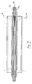
- Fig. 1
- einen Kommissionierautomat in einer schematischen Stirnansicht mit zwei gegenüberliegenden Regalen und einem zwischengeordneten Regalbediengerät,
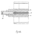
- Fig. 2
- das Regalbediengerät nach Fig. 1,
- Fig. 3
- das Regalbediengerät nach Fig. 2 in einer Seitenansicht mit Darstellung der höhenverstellbaren Bedienungseinheit,
- Fig. 4
- die Bedienungseinheit nach Fig. 3 in größerer Einzelheit,
- Fig. 5
- die Bedienungseinheit nach Fig. 4 in einer Stirnansicht, gesehen in Längsrichtung der Regale, mit Darstellung des querverlaufenden querverstellbaren Tisches,
- Fig. 6
- eine schematische Ansicht des Tisches nach Fig. 5 mit Darstellung des zweiten integrierten Endlos-Antriebes,
- Fig. 7
- den Tisch nach Fig. 6 in einer schematischen Draufsicht mit Darstellung des integrierten rechnergesteuerten ersten und zweiten Endlos-Antriebs,
- Fig. 8
- den Tisch nach Fig. 7 in einem schematischen Vertikalschnitt längs der Linie A-A der Fig. 7, mit Darstellung eines tischoberen Artikelanschlags,
- Fig. 9
- den Tisch nach den Fig. 8 in einem schematischen Vertikalschnitt längs der Linie B-B der Fig. 6,
- Fig. 10
- das linke Tischende der Fig. 7 in Draufsicht in größerer Einzelheit,
- Fig. 11
- den Artikelanschlag mit einem Abschnitt des zweiten Endlos-Antriebs in einer Draufsicht,
- Fig. 12
- den Artikelanschlag nach Fig. 11 in einer schematischen Seitenansicht bei einem linksseitigen Einlagern eines auf dem Tisch zwischengelagerten Artikels,
- Fig. 13
- einen Schacht eines Regals mit linkem Haltezinken in einer schematischen Seitenansicht, Stirnansicht und Draufsicht,
- Fig. 14
- zwei benachbarte untere Schachtenden mit Haltezinken, Positionierblechen und einem zwischengeordneten Haltezinken-Aufsteckblech,
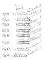
- Fig. 15
bis 17 - Zwischenschritte eines Auslagerns/links eines Artikels (aus einem nicht veranschaulichten linken Regalschacht), gesehen im Tischbereich ähnlich Fig. 6,
- Fig. 18
bis 20 - Zwischenschritte eines Auslagerns/rechts eines Artikels (aus einem nicht veranschaulichten rechten Regalschacht), gesehen im Tischbereich,
- Fig. 21
bis 28 - Zwischenschritte eines Auslagerns/rechts, gesehen im Bedienfinger- und Schachtbereich,
- Fig. 29
bis 31 - Zwischenschritte eines Einlagerns/links von Artikeln (in einen nicht veranschaulichten linken Regalschacht), gesehen im Tischbereich,
- Fig. 32 bis 34
- Zwischenschritte eines Einlagerns/rechts von Artikeln (in einen nicht veranschaulichten rechten Regalschacht), gesehen im Tischbereich,
- Fig. 35 bis 40
- Zwischenschritte eines Einlagerns/rechts, gesehen im Bedienfinger- und Schachtbereich,
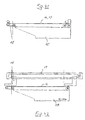
- Fig. 41
- eine andere Ausführungsvariante eines einseitigen Ketten- oder Zahnriementriebs für ein Aus- und Einlagern aus einem bzw. in einen linken nicht veranschaulichten Regalschacht, und
- Fig. 42
- eine dritte Ausführungsvariante eines einseitigen Lineartriebes für ein Aus- und Einlagern aus einem bzw. in einen linken nicht veranschaulichten Regalschacht.
- Fig. 1
- a picking machine in a schematic front view with two opposing shelves and an intermediate shelf operating device,
- Fig. 2
- the stacker crane according to FIG. 1,
- Fig. 3
- 2 in a side view showing the height-adjustable control unit,
- Fig. 4
- 3 in greater detail,
- Fig. 5
- 4 in an end view, seen in the longitudinal direction of the shelves, with the transverse transverse table being shown,
- Fig. 6
- 5 shows a schematic view of the table according to FIG. 5, showing the second integrated endless drive,
- Fig. 7
- 6 in a schematic plan view showing the integrated computer-controlled first and second endless drives,
- Fig. 8
- 7 in a schematic vertical section along the line AA of FIG. 7, showing an article stop above the table,
- Fig. 9
- 8 in a schematic vertical section along the line BB of FIG. 6,
- Fig. 10
- the left table end of Fig. 7 in plan view in greater detail,
- Fig. 11
- the article stop with a portion of the second endless drive in a plan view,
- Fig. 12
- 11 in a schematic side view with a left-sided storage of an article stored on the table,
- Fig. 13
- a shaft of a shelf with left holding tines in a schematic side view, front view and top view,
- Fig. 14
- two adjacent lower shaft ends with holding tines, positioning plates and an intermediate holding tine slip-on plate,
- 15 to 17
- Intermediate steps of outsourcing / left of an article (from a left shelf shaft, not shown), seen in the table area similar to FIG. 6,
- 18 to 20
- Intermediate steps of an outsourcing / right of an article (from a not illustrated right shelf shaft), seen in the table area,
- 21 to 28
- Intermediate steps of outsourcing / right, seen in the operating finger and shaft area,
- 29 to 31
- Intermediate steps of storing / left of articles (in a not illustrated left shelf shaft), seen in the table area,
- 32 to 34
- Intermediate steps of storing / on the right of articles (in a not illustrated right shelf slot), seen in the table area,
- 35 to 40
- Intermediate steps of storage / right, seen in the operating finger and shaft area,
- Fig. 41
- another embodiment variant of a one-sided chain or toothed belt drive for removal and storage from or into a shelf shaft, not shown on the left, and
- Fig. 42
- a third embodiment of a one-sided linear drive for removal and storage from or into a shelf shaft, not shown, on the left.
Gemäß Fig. 1 umfaßt ein Kommissionierautomat 1 zur automatischen
Kommissionierung von Artikeln 2 zwei gegenüberliegende,
zueinander parallele, geradlinige, voneinander beabstandete
Regale 3 mit einer mittleren Regalgasse in Regallängsrichtung.1 comprises an
Jedes Regal 3 besitzt übereinander und nebeneinander angeordnete
Schächte 4, welche sich in Regalquerrichtung Z erstrecken
und in ihrer Längsrichtung gegenüber der Horizontalen
geneigt sind. In den oder in einzelnen Schächten befinden
sich jeweils sortengleiche Artikel, welche hintereinander
gelagert sind. Each
Die Neigung der Schächte 4 ist so gewählt, daß die eingelagerten
Artikel aufgrund ihres Eigengewichts nach unten rutschen
können. Die oben und unten endseitig offenen Schächte
besitzen am schachtunteren Ende, welches einem Regalbediengerät
10 gemäß Fig. 1 bis 12 zugewandt ist, jeweils zumindest
einen vom Schachtboden nach oben weisenden Haltezinken 22
gemäß Fig. 13, 14, welcher den schachtuntersten Artikel und
mithin gegebenenfalls nachgeordnete Artikel des gleichen
Schachts festhält bzw. am Ausrutschen aus dem Schacht 4 hindert.The inclination of the
Die Regale 3 besitzen längsendseitig jeweils eine Auslaßrutsche
5 für kommissionierte Artikel 2, welche entgegengesetzt
zu den Schächten 4 gegenüber der Horizontalen geneigt ist.The
In der Regalgasse befindet sich mittig das Regalbediengerät
10, welches in Regallängsrichtung X durch einen ersten Antrieb
12 auf Schienen 7 zumindest zwischen den beiden Regalen
3 verfahrbar ist. Der Antrieb 12, wie auch die nachfolgend
noch genannten anderen Antriebe 13, 14, 16 und 17, ist
bzw. sind rechnergesteuert. Das diese Antriebe steuernde
elektronische Steuergerät 8 ist am Regalbediengerät 10 befestigt.The storage and retrieval machine is located in the center of the
Das Regalbediengerät 10 umfaßt eine Bedienungseinheit 11,
welche durch einen zweiten Antrieb 13 in Regalhochrichtung Y
höhenverstellbar ist.The storage and
Die höhenverstellbare Bedienungseinheit besitzt ihrerseits
einen querverlaufenden Tisch 15, welcher in Regalquerrichtung
Z durch einen dritten Antrieb 14 querverstellbar ist.The height-adjustable control unit in turn has
a transverse table 15 which is in the transverse direction of the shelf
Z is transverse adjustable by a
Die Anordnung ist so getroffen, daß der querverlaufende
Tisch 15 der Bedienungseinheit 11 bei jedem unteren
Schachtende durch den ersten, den zweiten und den dritten
Antrieb 12, 13 und 14 positionierbar ist. Die Ansteuerung
erfolgt entsprechend der dem Steuergerät 8 eingegebenen
Software.The arrangement is such that the transverse
Table 15 of the operating
Auf dem querverlaufenden Tisch 15 können Artikel 2, insbesondere
gemäß Fig. 4 bis 12, in Regalquerrichtung Z zwischengelagert
werden, um diese Artikel in einen ausgewählten
Schacht 4 durch das untere Schachtende einzulagern bzw.
einzuschieben, wie nachfolgend noch beschrieben wird.On the transverse table 15,
Die Anordnung ist ferner so getroffen, daß auch Artikel aus dem Schacht auf den Tisch über das untere Schachtende ausgelagert und dort zwischengelagert werden können.The arrangement is also such that articles are made outsourced the shaft to the table over the lower end of the shaft and can be stored there temporarily.
Im Tisch 15 sind ein in Regalquerrichtung Z verlaufender,
rollengeführter, rechnergesteuerter, erster Endlos-Antrieb
16 und ein in Regalquerrichtung Z verlaufender, rollengeführter,
rechnergesteuerter, zweiter Endlos-Antrieb 17 zur Horizontalförderung
von Artikeln 2 auf dem Tisch 15 ausgebildet.
Der obere Trum eines jeden Endlos-Antriebs 16 und 17 ist
hierbei in der Tischoberseite gemäß Fig. 7 bis 10 integriert.
Im Tisch 15 befinden sich die Antriebsrollen und
- zahnräder sowie leerlaufende Umlenkrollen der Endlos-Antriebe
16, 17.In the table 15 there is a
roller-guided, computer-controlled, first
Der erste Endlos-Antrieb 16, welcher aus mehreren parallelen
synchron angetriebenen Rund-Riementrieben besteht, ist hierbei
zum Auslagern von Artikeln aus einem ausgewählten
Schacht 4 vorgesehen, während der zweite Endlos-Antrieb 17,
welcher ein Kettenantrieb ist, zum Einlagern von Artikeln in
einem ausgewählten Schacht 4 bestimmt ist.The first
Der zweite Endlos-Antrieb 17 ist mittig gemäß Fig. 7 und 10
im querverlaufenden Tisch 15 angeordnet, während der erste
Endlos-Antrieb 16 beidseits des zweiten Endlos-Antriebes 17
symmetrisch zu diesem Antrieb 17 verläuft.The second
Der zweite Endlos-Antrieb 17 in Form eines Kettentriebs umfaßt
gemäß Fig. 6 drei auf dem Endlos-Umfang gleich verteilte
hervorstehende Artikelanschläge 18, welche, in Fig. 6
schraffiert dargestellt, senkrecht an entsprechenden Kettenlaschen
19 gemäß Fig. 12 des Kettentriebs befestigt sind.
Die Artikelanschläge 18 erfüllen eine Doppelfunktion, wie
nachfolgend noch beschrieben wird.The second
Die Artikelanschläge 18 sind mittig gemäß Fig. 8, 9 und 11 unterteilt, wobei beide Anschlaghälften seitlich vom Kettentrieb liegen, so daß im Tischinneren der Rücklauftrum der Kette über Antriebszahnräder laufen kann.The article stops 18 are in the center according to FIGS. 8, 9 and 11 divided, with both halves of the stop laterally from Chain drive lie so that the return run inside the table the chain can run over drive sprockets.
Gemäß Fig. 6, 7 sind der erste und der zweite Endlos-Antrieb
16, 17 als Umkehrtriebe ausgebildet, welche in beiden Regalquerrichtungen
Z unabhängig voneinander betrieben werden
können.6, 7 are the first and the second
Der querverlaufende Tisch 15 weist gemäß Fig. 6, 7, 10 an
seinen beiden Querenden mittig jeweils einen in Draufsicht
schmalen Bedienfinger 20 auf, in welchem auch der erste und
der zweite Endlos-Antrieb 16, 17 integriert ausgebildet ist.The transverse table 15 shows according to FIGS. 6, 7, 10
its two transverse ends in the middle one in plan view
Der Bedienfinger 20 kann bei einer Auslagerung eines ausgewählten
schachtuntersten Artikels 2 auf den Tisch 15 oder
bei einer Einlagerung eines Artikels vom Tisch 15 in einen
ausgewählten Schacht 4 mit der Bodenseite dieses Artikels in
Eingriff gebracht werden, wie dies insbesondere in Fig. 23
bis 26 und 37 bis 39 gezeigt ist.The operating
Der Boden eines jeden Schachts 4 des Regals 3 umfaßt an der
schachtunteren, dem Regalbediengerät 10 zugewandten Seite
eine zentrale Aussparung 21 gemäß Fig. 13, welche geringfügig
größer als der Bedienfinger 20 in Draufsicht ist, wobei
bei einem bei einem unteren Schachtende positionierten Regalbediengerät
der Bedienfinger 20 berührungsfrei in der Aussparung
aufnehmbar ist, d.h. berührungsfrei nach oben oder nach
unten bei Betätigung des zweiten Antriebs 13 hindurchbewegt
werden kann.The bottom of each
Der hochstehende Haltezinken 22 kann höhen- und/oder seitenverstellbar
ausgebildet sein.The
Auch kann der hochstehende Haltezinken 22 in Form und Größe
auch durch Zusatzformbleche bzw. Haltezinken-Aufsteckbleche
9, beispielsweise gemäß Fig. 14, verändert werden.The
Jede Schachtdeckwand 23 ist bezüglich des Haltezinkens 22
regalseitig gemäß Fig. 14 zurückversetzt ist und weist einen
nach oben abgewinkelten Rand 24 auf, welcher den Durchlauf
eines Artikels am unteren Schachtende bei einem Einlagern
oder einem Auslagern erleichtert.Each shaft
Der querverlaufende Tisch 15 weist tischoberseitig einen höhenverstellbaren
Artikelniederhalter und eine verstellbare
Artikel-Seitenführung auf jeder Seite des zweiten Endlos-Antriebs
17 in Form von zwei abgewinkelten Leitschienen 25
auf, wobei beide Leitschienen 25 bezüglich der Querachse des
Tisches 15 synchron bzw. gleichzeitig seiten- und höhenverstellbar
sind. Die Leitschienen 25 besorgen insbesondere bei
einem Einlagern von Artikeln im Schacht vorab ein Zentrieren
des Artikelanschlags 18 sowie.ein Ausrichten der auf dem
Tisch 15 gelagerten Artikel 2 vor einem Einschieben in das
Regal an ausgewählter Stelle.The transverse table 15 has a height-adjustable top of the table
Article hold-down and an adjustable
Article guiding on each side of the second
Der Artikelanschlag 18 weist, gesehen in Regallängsrichtung
Z, eine abgerundete Form auf, wie dies insbesondere den Fig.
11 und 12 zu entnehmen ist.The
Rollen 26 des ersten und des zweiten Endlos-Antriebes 16, 17
können auf einer gemeinsamen Achse 27 gemäß Fig. 8 gelagert
sein.
Jeder Schacht 4 weist gemäß Fig. 13, 14 am unteren Ende ein
Positionierblech 28 zum Auffinden des Regalortes mit Hilfe
einer systemeigenen Sensorik auf, welche an das Steuergerät
8 angeschlossen ist.13, 14 at the lower
Die vorstehende Gesamtanordnung ist nun so getroffen, daß bei einem automatischen Auslagern von Artikeln gemäß Fig. 15 bis 28 aus den Regalen 3 mit in schrägen Schächten des Regals hintereinander angrenzend gelagerten Artikeln, wobei jeweils der schachtunterste Artikel gegen ein Herausrutschen aus dem Schacht 4 durch den feststehenden Haltezinken 22 am unteren Schachtende gesichert wird, das Regalbediengerät 10 durch den ersten, den zweiten und den dritten rechnergesteuerten Antrieb 12, 13, 14 zum unteren Ende des ausgewählten Schachts 4 bewegt und der Bedienfinger 20 dicht unterhalb des Schachtendes unter der Aussparung 21 positioniert wird, daß bei eingeschaltetem kontinierlich laufenden ersten Endlos-Antrieb 16 die Bedienungseinheit 11 nebst Tisch 15 einschließlich Bedienfinger 20 durch den zweiten Antrieb 13 so weit angehoben wird, daß der Bedienfinger 20 berührungsfrei durch die Aussparung 21 gelangt und dabei den schachtuntersten Artikel bodenseitig untergreift und dergestalt anhebt, daß (nebst eventuell weiterer Artikel im Schacht) der zweitunterste Artikel im Schacht 4 bis zum Haltezinken 22 nachrutscht und der zuvor schachtunterste Artikel durch den ersten Endlos-Antrieb 16 in Querrichtung weg vom Regal 3 auf dem Tisch 15 bis zu einem auf der anderen Tischseite durch Stellbetrieb des zweiten Endlos-Antriebes 17 positionierten Artikelanschlag 18 (z. B. gemäß Fig. 6, tischoberseitig rechts, schraffiert) gefördert wird, worauf die Bedienungseinheit 11 gegebenenfalls durch den dritten Antrieb 14 in eine regalferne Neutralposition bewegt wird.The overall arrangement above is now made such that in the case of automatic outsourcing of articles according to FIG. 15 to 28 from shelves 3 with in sloping shafts of the shelf successively stored articles, whereby the bottom-most article against slipping out from the shaft 4 through the fixed holding tines 22 on the lower shaft end is secured, the storage and retrieval machine 10 by the first, the second and the third computer-controlled Drive 12, 13, 14 to the lower end of the selected one Shaft 4 moves and the operating finger 20 just below the shaft end is positioned under the recess 21, that when the continuously running first endless drive is switched on 16 the operating unit 11 including table 15 inclusive Operating fingers 20 through the second drive 13 so is raised far that the operating finger 20 without contact passes through the recess 21 and the bottom of the shaft Reaches under the bottom of the article and lifts it that (along with any other items in the shaft) is the second lowest Article slips in the shaft 4 until the holding prong 22 and the previously bottom-most article by the first endless drive 16 in the transverse direction away from the shelf 3 through table 15 to one on the other side of the table Positioning operation of the second endless drive 17 positioned Article stop 18 (e.g. according to FIG. 6, on the table top right, hatched) is promoted, whereupon the operating unit 11 if necessary by the third drive 14 in a neutral position away from the shelf is moved.
Bei einer Bedienung eines gegenüberliegenden Regals 3 wird
der erste Endlos-Antrieb 16 in der Drehrichtung umgeschaltet
und der Artikelanschlag 18 des zweite Endlos-Antriebs 17 auf
der anderen Tischquerseite gemäß Fig. 18 bis 20 (vgl. demgegenüber
Fig. 15 bis 17) positioniert. Hierbei braucht der
zweite Endlos-Antrieb in der Drehrichtung nicht umgeschaltet
zu werden. Es genügt ein kurzer Verstellbetrieb, um einen
(anderen) Artikelanschlag auf der anderen Tischoberseite zu
positionieren.When an
Ist der Auslagerungsvorgang abgeschlossen, wird das Regalbediengerät
10 zu der auf der Längsseite des Regals 3 gelegenen
Übergabestelle 3 gemäß Fig. 1 über eine vorgelagerte Auslaßrutsche
5 bewegt, welche bezüglich der Horizontalen in
der Gegenrichtung der Schächte geneigt ist.When the outsourcing process is complete, the storage and retrieval machine becomes
10 to that located on the long side of the
Bei einem automatischen Einlagern von Artikeln gemäß Fig. 29
bis 40 mit Hilfe eines Kommissionierautomaten 1 der vorstehend
beschriebenen Art wird der Artikelanschlag 18 des zweiten
Endlos-Antriebes 17 auf der regalfernen Tischoberseite
positioniert und durch einen geschlossenen Zentrierer zentriert.
Die einzulagernden hintereinander auf der Tischoberseite
angeordneten Artikel 2 werden durch Verstellen der
Artikel-Seitenführung im wesentlichen mittig ausgerichtet
und durch den Artikel-Niederhalter in der Höhe geführt. Anschließend
werden die Artikel durch den Artikelanschlag 18
durch Betrieb des zweiten Endlos-Antriebs 17 in entsprechender
Drehrichtung in eine regalnahe Einlagerungsposition auf
dem Tisch 15 vorgeschoben, wobei der Bedienfinger 20 artikelfrei
gehalten wird. Anschließend wird der Bedienfinger 20
unterhalb der Aussparung 21 des ausgewählten Schachts 4
durch Betätigung des ersten, zweiten und dritten Antriebes
12, 13, 14 positioniert. Durch den zweiten Antrieb 13 wird
dann der Bedienfinger 20 nebst Tisch so weit angehoben wird,
daß der Bedienfinger berührungsfrei durch die Aussparung 21
gelangt und dabei den schachtuntersten Artikel bodenseitig
untergreift und dergestalt anhebt, daß (nebst eventuell weiterer
Artikel im Schacht) der zweitunterste Artikel im
Schacht 4 bis zu den vorpositionierten einzulagernden Artikeln
auf dem Tisch 15 nachrutscht und die Artikel aufgrund
des Eigengewichts der Artikelreihe gegen den Artikelanschlag
18 schiebt. Dann wird der zweite Endlos-Antrieb 17 in einen
Stellbetrieb genommen, wobei der Artikelanschlag 18 in Richtung
Regal 3 bis unmittelbar zum Bedienfingerende gemäß Fig.
31, 34 tischoberseitig bewegt wird. Dabei schiebt der Artikelanschlag
18 die einzulagernden Artikel 2 in den ausgewählten
Schacht. Anschließend wird der Bedienfinger nebst Tisch
durch den zweiten Antrieb 13 berührungsfrei durch die Aussparung
21 nach unten verstellt, wodurch die Artikel 2 in
Schacht 4 gegen den Haltezinken 22 rutschen.In the case of automatic storage of articles according to FIG. 29
to 40 with the help of an
Gegebenenfalls wird der gleiche Schacht nochmals oder ein anderer ausgewählter Schacht entsprechend angefahren und bedient, bis der Einlagerungsauftrag abgeschlossen ist.If necessary, the same shaft is again or one other selected shaft approached accordingly and served until the storage order is completed.
Wie. beim Auslagern, wird auch beim Einlagern von Artikeln
bei einer Bedienung eines gegenüberliegenden Regals 3 der
Tisch 15 seitenverkehrt betrieben. Insbesondere wird ein Artikelanschlag
18 des zweite Endlos-Antriebs 17 vor einem Einschieben
der Artikel in den Schacht auf der anderen Tischquerseite
positioniert, wie dies im Zusammenhang mit dem
Auslagern beschrieben worden ist.How. when outsourcing, also when storing articles
when operating an
Durch das Regalbediengerät 10 können nicht nur ausgewählte
Artikel aus Schächten 4 ausgelagert, sondern auch an anderer
Regalstelle eingelagert, d.h. ausgewählte Artikel im Regal 3
umgelagert werden.The storage and
Mit Bezug auf die Fig. 21 bis 28 geht ein Auslagern von Artikeln
wie folgt vonstatten:
Achsbewegung +Y; Die Y-Achse wird bis zur Sollposition in der Höhe verfahren. Die Sollposition liegt unterhalb des Schachts, aus dem ein Artikel entnommen werden soll (Y-Achse) und genau in der Mitte des Schachtes (X-Achse).
Axis movement + Y; The height of the Y axis is moved to the target position. The target position is below the shaft from which an article is to be taken (Y axis) and exactly in the middle of the shaft (X axis).
Mit Bezug auf die Fig. 35 bis 40 geht ein Einlagern von Artikeln
wie folgt vonstatten:
Achsbewegung +Y; Die Y-Achse wird bis zur Sollposition in der Höhe verfahren. Die Sollposition liegt unterhalb des Schachts, in der ein Artikel eingelagert werden soll (Y-Achse) und genau in der Mitte des Schachts (X-Achse).
Axis movement + Y; The height of the Y axis is moved to the target position. The target position is below the shaft in which an article is to be stored (Y axis) and exactly in the middle of the shaft (X axis).
Die schließlich in den Fig. 41 und 42 veranschaulichten Ausführungsvarianten einer Entnahmeeinheit bzw. eines querverlaufenden Tisches 15 sind für eine einseitige Artikeleinlagerung und -auslagerung bei einem nicht veranschaulichten linken Regal konzipiert und im Vergleich zu der vorgenannten Ausführungsvariante nicht symmetrisch, sondern asymmetrisch ausgebildet. Beide Varianten arbeiten mit einem einzigen Schieber für ein Einlagern der Artikel.The embodiment variants finally illustrated in FIGS. 41 and 42 a removal unit or a transverse one Tables 15 are for one-sided article storage and outsourcing one not illustrated left shelf designed and compared to the aforementioned Version not symmetrical, but asymmetrical educated. Both variants work with one Slider for storing the articles.
Gemäß Fig. 41 sind die beiden Motoren M für den Schieber und den Riemen hintereinander im Bereich der Tischoberseite an einem Querende (rechts) vorgesehen. Im besonderen zeigt Fig. 41 eine Kette oder Zahnriemenlösung.41, the two motors M for the slide and the straps one behind the other in the area of the table top a transverse end (right) provided. In particular, Fig. 41 a chain or toothed belt solution.
Fig. 42 veranschaulicht eine Lineareinheitslösung, bei der der Schieber bezüglich des Tisch-Förderbandes hochgelagert ist, entsprechend hoch gelagert auch der Schiebermotor. Bei letztgenannter Variante kann der Entnahme- bzw. Bedienfinger 20 sehr schmal ausgebildet werden.Fig. 42 illustrates a linear unit solution in which the slider is raised with respect to the table conveyor belt the slide motor is correspondingly high. at the latter or the removal finger can be used 20 are very narrow.
Für jede Regalseite kann eine einseitige vorgenannte Entnahmeeinheit verwendet werden, oder bei einer einzigen Entnahmeeinheit diese Entnahmeeinheit um das Regal gefahren werden, um beide Regalseiten zu bedienen.A unilateral removal unit can be used for each shelf side be used, or with a single extraction unit this removal unit is moved around the shelf, to serve both sides of the shelf.
Claims (14)
- An automatic order-picking machine (1) for automatic order picking of articles (2), having at least one shelf (3) comprising superposed arrays of chutes (4) or trays disposed side by side and extending transversely across the shelf and sloping downwardly in their longitudinal direction, in which chutes articles ofthe same kind can be stored one behind the other such that when the lowermost article is removed or picked out, the other articles in the chute (4) or on the tray can slide down to replace it, and having a shelf-serving device (10) individually assigned to said shelf (3) and exhibiting a computer-controlled control unit (11) which can be positioned at each end of the chute and is responsible for both picking out and putting in articles (2), and said control unit (11) of the shelf-serving device can be moved in the longitudinal direction ofthe shelf (3) by a computer-controlled first drive (12) and can be vertically adjusted by a computer-controlled second drive (13) and comprises a table (15) extending transversely to the longitudinal direction of the shelf and on which articles (2) to be put in or articles (2) which have been picked out can be interim-stored in the transverse direction of the shelf, which table (15) can be moved in the transverse direction of the shelf by a computer-controlled third drive (14), and in the table (15) there are provided a first roller-guided, computer-controlled, continuous drive (16) extending in the transverse direction ofthe shelf and a further computer-controlled drive extending in the transverse direction ofthe shelf for horizontal transportation of articles (2) along the table (15), said first continuous drive (16) being provided for the picking articles out of a selected chute (4) and said other drive being provided for putting articles into a selected chute (4), characterized in that said other drive is in the form of a roller-guided, second continuous drive (17) and is disposed in the center of the transverse table (15), whilst the first continuous drive (16) is disposed on each side ofthe second continuous drive (17) symmetrically to said second continuous drive (17).
- An automatic order-picking machine as claimed in claim 1, characterized in that the second continuous drive (17) has at least one projecting stop member (18), preferably three stop members (18) equally distributed on the continuous loop of the second continuous drive (17) and, in particular, the second continuous drive (17) is a chain drive, and said stop member (18) is attached vertically to a chain shackle (19) ofthe chain drive, said stop member (18) is divided at its center ie the two halves of the stop member are located laterally ofthe chain drive and, in particular, the first continuous drive (16) comprises one or more synchronous flat belt drives or synchronous round belt drives.
- An automatic order-picking machine as defined in claim 1 or claim 2, characterized in that two opposite rows of shelves are provided which are set at a distance from each other in a straight line, the shelf-serving device (10) being in a longitudinally central position in the lane between said rows of shelves where it can be moved or displaced in the longitudinal direction of the shelf (3) and that the first and second continuous drives (16, 17) are reversible drives which can be independently operated in both transverse directions ofthe shelf.
- An automatic order-picking machine as defined in any one of claims 1 to 3, characterized in that the transverse table (5) has at at least one end a centrally disposed finger (20), in which the first and second continuous drives (16, 17) are also integrated, which finger (20) is capable of engaging the bottom surface of an article when the selected lowermost article (2) in a chute is to be picked out or an article is to be taken from the table (15) for insertion into a selected chute (4), and that the bottom of a chute (4) or each tray in the shelf (3) has a central opening (21) at the bottom end of the chute, facing the shelf-serving device, which opening is slightly larger than the finger (20) when viewed from above, and when the shelf-serving device (20) is positioned at the lower end of a chute, the finger (20) can move into the opening without touching it, ie it can be moved up and down in said opening without touching it.
- An automatic order-picking machine as defined in any one of claims 1 to 4, characterized in that the lower end of the chute base has at least one vertical retaining prong (22), which is preferably vertically and/or laterally displaceable, and, in particular, the chute cover (23) is in staggered relationship with the retaining prong (22) on the shelf side and exhibits an upturned edge (24) or in the cover area of a tray there is provided an article depresser which is in staggered relationship with the vertical retaining prong on the shelf side.
- An automatic order-picking machine as defined in any one of claims 1 to 5, wherein the table (15) has a centering device for the stop members and/or a variable lateral guide for the articles and/or a vertically adjustable article depresser, and particularly the vertically adjustable article depresser and the variable lateral guide for the articles on each side ofthe second continuous drive (17) is an angle-section guide rail (25) and both guide rails (25) can be synchronously or simultaneously displaced with respect to the transverse axis of the table (15).
- A method of automatically removing articles with the aid of an automatic order-picking machine as defined in any one of claims 1 to 6, in which articles have been stored in adjacent relationship to each other in inclined chutes of the shelf and in each case the lowermost article in the chute is secured against slipping out ofthe chute by the stationary retaining prong at the lower end of the chute, characterized in that that the shelf-serving device (10) is moved by a first, second and third computer controlled drive (12, 13, 14) to the lower end ofthe selected chute (4) and the finger (20) is positioned below the end ofthe chute underneath the opening (21) and that when the first continuous drive (16) is switched on and running continuously, the control unit (11) with its table (15) including finger (20) is raised and lowered by the second drive (13) to such an extent that the finger (20) enters the opening (21) without touching it and engages the lowermost article in the chute from underneath and raises and lowers it in such a manner that the second lowest articles in the chute (4) and any other articles in the chute slip down as far as the retaining prong (22) and the previously lowermost article in the chute is transported by the first continuous drive (16) in the transverse direction along the table (15) away from the shelf (3) to a stop member (18) on the other side of the table, which stop member has been positioned by operation of the second continuous drive (17) in the direction of transport and is disposed centrally between the two first continuous drive units, after which the control unit (11) is moved by at least the third drive (14) to a neutral position remote from the shelf.
- A method as defined in claim 7, characterized in that the same chute is again served or another selected chute is served in the same way until the pick-out job is completed or the table is completely loaded with picked-out articles.
- A process as defined in claim 7 or claim 8, characterized in that the shelf-serving device (10) is moved to a discharge point (30) located on the long side ofthe shelf (3) or between two shelves (3), at which discharge point the article stored on the table (15) is transferred by operation of the first or second continuous drive (16, 17) to a receptacle and/or a conveyor belt or an exit chute (5).
- A method as defined in any one of claims 7 to 9, carried out with the aid of an automatic order-picking machine between at least two opposing shelves set at a distance from each other, characterized in that when an opposing shelf (3) is served, at least the first continuous drive (16) is reversed and the stop member (18) ofthe second continuous drive (17) is positioned at the other short side of the table.
- A method of automatically storing articles with the aid of an automatic order-picking machine as defined in any one of claims 1 to 6, characterized in that the stop member (18) of the second continuous drive (17) is positioned on the table top that is remote from the shelf centrally in the direction of transport between the drive parts ofthe first continuous drive and is optionally centered by a closed centering unit,
that the articles to be inserted and located in succession on the table top are oriented in a central position by adjustment ofthe position of the lateral guide for the articles and are vertically guided by the article depresser,
that the articles are pushed forward on the table (15) by the stop member (18) to an inserting position near the shelf, the finger (20) being kept free from articles,
that the finger (20) is moved to a position underneath the opening (21) of the selected chute (4) by operation ofthe first, second and third drives 12, 13, 14),
that the second drive (13) raises the finger (20) plus the table such that the finger passes into the opening (21) without touching it and thus engages the lowermost article in the chute from below and raises the same in such a manner that the second lowest article and any other articles in the chute (4) slip down to the prepositioned articles to be inserted and located on the table (15) and pushes these articles against the stop member (18),
that the second continuous drive (17) is switched to put-in operation and moves the stop member (18) in the direction of the shelf (3) to a position directly in front of the end of the finger on the table top to push the articles to be inserted into the selected chute,
that the finger plus table is lowered by the second drive (13), and passes into the opening (21) without touching it, and the articles (2) in the chute (4) slip against the retaining prong (22), after which the control unit (11) is moved by at least the third drive (14) to a neutral position remote from the shelf. - A method as defined in claim 11, characterized in that the same chute is again served or another selected chute is served in a similar manner until the put-in job is completed.
- A method as defined in claim 11 or claim 12, carried out with the aid of an automatic order-picking machine located between at least two opposing shelves set at a distance from each other, characterized in that when an opposing shelf (3) is served, the table (15) is operated in reverse and the stop member (18) of the second continuous drive (17) is positioned on the other short side of the table before the article is inserted into the chute.
- A method as defined in any one of claims 7 to 13, characterized in that selected articles are picked out from chutes (4) by the shelf-serving device (10) and are inserted at some other shelf site, ie selected articles are cross-loaded within the shelf (3).
Applications Claiming Priority (2)
| Application Number | Priority Date | Filing Date | Title |
|---|---|---|---|
| DE19714455 | 1997-02-24 | ||
| DE19714455A DE19714455A1 (en) | 1997-02-24 | 1997-02-24 | Method and device for automatic order picking |
Publications (3)
| Publication Number | Publication Date |
|---|---|
| EP0866002A2 EP0866002A2 (en) | 1998-09-23 |
| EP0866002A3 EP0866002A3 (en) | 1999-12-15 |
| EP0866002B1 true EP0866002B1 (en) | 2003-05-07 |
Family
ID=7825783
Family Applications (1)
| Application Number | Title | Priority Date | Filing Date |
|---|---|---|---|
| EP98103108A Expired - Lifetime EP0866002B1 (en) | 1997-02-24 | 1998-02-23 | Method and device for the automatic order picking of articles |
Country Status (3)
| Country | Link |
|---|---|
| EP (1) | EP0866002B1 (en) |
| AT (1) | ATE239651T1 (en) |
| DE (2) | DE19714455A1 (en) |
Cited By (1)
| Publication number | Priority date | Publication date | Assignee | Title |
|---|---|---|---|---|
| CN101054127B (en) * | 2007-05-18 | 2011-07-20 | 苏州艾隆科技有限公司 | Slope-type medicament storeroom |
Families Citing this family (9)
| Publication number | Priority date | Publication date | Assignee | Title |
|---|---|---|---|---|
| DE10021365C2 (en) * | 2000-05-02 | 2002-06-13 | P & P Materialflussysteme Gmbh | Operating arrangement for operating a product storage rack, in particular a picking device |
| DE10130984B4 (en) * | 2001-06-27 | 2004-03-25 | Knapp Logistik Automation Ges.M.B.H. | Storage and retrieval machine and method for operating a product storage rack, in particular a picking device |
| ITMI20051727A1 (en) * | 2005-09-19 | 2007-03-20 | Bottigelli Service S R L | STORAGE AND WITHDRAWAL OF PRODUCT AND ITS MANAGEMENT PROCEDURE |
| US7686560B2 (en) * | 2005-12-08 | 2010-03-30 | Conestoga Cold Storage | Rack, conveyor and shuttle automated pick system |
| EP1806302A1 (en) * | 2006-01-05 | 2007-07-11 | von Liechtenstein, Alexander | Method and device for commisioning and storing products |
| CN102390652A (en) * | 2011-07-19 | 2012-03-28 | 江苏迅捷装具科技有限公司 | 'h'-shaped storage tank and combined storage rack |
| AT512970A1 (en) * | 2012-04-11 | 2013-12-15 | Knapp Systemintegration Gmbh | Method and device for sorting goods, in particular beverage crates |
| CN107176405B (en) * | 2016-03-10 | 2023-10-10 | 周兆弟 | Building material automatic storage device |
| US20240005270A1 (en) * | 2022-07-02 | 2024-01-04 | Printec Bulgaria Jsc | Increasing the capacity of different types of products and matching stock with forecasted sales volumes per product type in automatic vending machines |
Family Cites Families (6)
| Publication number | Priority date | Publication date | Assignee | Title |
|---|---|---|---|---|
| US3750804A (en) * | 1969-03-07 | 1973-08-07 | Triax Co | Load handling mechanism and automatic storage system |
| GB2205822A (en) * | 1987-06-18 | 1988-12-21 | Supac Systems Inc | Container extraction and transfer mechanism for an automated storage and retrieval system |
| DE9301797U1 (en) * | 1993-02-09 | 1993-07-22 | Frazier Industrial Co., Long Valley, N.J., Us | |
| US5551823A (en) * | 1993-08-20 | 1996-09-03 | Tsubakimoto Chain Co. | Transfer apparatus having traction pin moved with height difference |
| DE9409881U1 (en) * | 1994-06-18 | 1994-09-15 | P & P Materialflussysteme Gmbh | Order picking system |
| DE29703230U1 (en) * | 1997-02-24 | 1997-07-31 | P & P Materialflussysteme Gmbh | Automatic picking machine for automatic picking of articles |
-
1997
- 1997-02-24 DE DE19714455A patent/DE19714455A1/en not_active Withdrawn
-
1998
- 1998-02-23 AT AT98103108T patent/ATE239651T1/en not_active IP Right Cessation
- 1998-02-23 EP EP98103108A patent/EP0866002B1/en not_active Expired - Lifetime
- 1998-02-23 DE DE59808215T patent/DE59808215D1/en not_active Expired - Fee Related
Cited By (1)
| Publication number | Priority date | Publication date | Assignee | Title |
|---|---|---|---|---|
| CN101054127B (en) * | 2007-05-18 | 2011-07-20 | 苏州艾隆科技有限公司 | Slope-type medicament storeroom |
Also Published As
| Publication number | Publication date |
|---|---|
| EP0866002A2 (en) | 1998-09-23 |
| DE19714455A1 (en) | 1998-09-03 |
| ATE239651T1 (en) | 2003-05-15 |
| EP0866002A3 (en) | 1999-12-15 |
| DE59808215D1 (en) | 2003-06-12 |
Similar Documents
| Publication | Publication Date | Title |
|---|---|---|
| DE19509951C2 (en) | Device for unsorted storage of goods or other objects | |
| DE4336885A1 (en) | Commissioning system for pharmacy products | |
| EP1889800A2 (en) | Shelving system and method for automatic storage of smalls | |
| DE19815883A1 (en) | Order picking system | |
| EP1762511B1 (en) | Automatic warehouse comprising an operating device with a buffer shaft and method for operating the warehouse | |
| DE202012012928U1 (en) | Device for storing goods, in particular medicines | |
| EP0866002B1 (en) | Method and device for the automatic order picking of articles | |
| DE3830373A1 (en) | Automatically functioning storage and transport system for supplying items to and removing them from workstations | |
| EP2199229A2 (en) | Load-carrying assembly for a shelf serving device, supply assembly with a shelf serving device and method for operating a supply assembly | |
| DE19812147A1 (en) | Order commissioning completion system with automatic machine | |
| EP2163491B1 (en) | Warehouse robot | |
| EP0062233B1 (en) | Consignment conveying plant with transfer stations successively arranged in the direction of transport | |
| DE102004025070B4 (en) | Method and device for storing goods in an automated storage device | |
| EP0526403A1 (en) | Method and device for making groups of food discs | |
| EP0496992A1 (en) | Tray loading and unloading device | |
| DE10130984B4 (en) | Storage and retrieval machine and method for operating a product storage rack, in particular a picking device | |
| DE102004059809B4 (en) | Method and device for loading and unloading of stored goods from shelves of a storage rack | |
| EP0869084B1 (en) | Shelving system comprising trays for conveying material and a device for handling the trays | |
| EP1652799B1 (en) | Device for separating piece goods | |
| DE10015272C2 (en) | Device for storing and retrieving load carriers in a rack warehouse | |
| EP0560206B1 (en) | Retrieval system for the automatic selection of articles | |
| EP0416627A1 (en) | Method and device for storing goods and automatically selecting them from shelves in large scale stores | |
| EP2163492A2 (en) | Combined warehouse | |
| DE19618918C2 (en) | Automatic picking system for the automatic picking and dispatching of stacked articles | |
| DE10008362A1 (en) | Shelf storage system for piece goods, in particular, for dispatch of medicament packages comprises a supply station which has a single supply opening and receptacles formed by inclined but mutually orthogonal bearing surfaces |
Legal Events
| Date | Code | Title | Description |
|---|---|---|---|
| PUAI | Public reference made under article 153(3) epc to a published international application that has entered the european phase |
Free format text: ORIGINAL CODE: 0009012 |
|
| AK | Designated contracting states |
Kind code of ref document: A2 Designated state(s): AT BE CH DE ES FR GB IT LI NL |
|
| AX | Request for extension of the european patent |
Free format text: AL;LT;LV;MK;RO;SI |
|
| PUAL | Search report despatched |
Free format text: ORIGINAL CODE: 0009013 |
|
| AK | Designated contracting states |
Kind code of ref document: A3 Designated state(s): AT BE CH DE DK ES FI FR GB GR IE IT LI LU MC NL PT SE |
|
| AX | Request for extension of the european patent |
Free format text: AL;LT;LV;MK;RO;SI |
|
| 17P | Request for examination filed |
Effective date: 20000426 |
|
| AKX | Designation fees paid |
Free format text: AT BE CH DE ES FR GB IT LI NL |
|
| 17Q | First examination report despatched |
Effective date: 20010821 |
|
| GRAH | Despatch of communication of intention to grant a patent |
Free format text: ORIGINAL CODE: EPIDOS IGRA |
|
| GRAH | Despatch of communication of intention to grant a patent |
Free format text: ORIGINAL CODE: EPIDOS IGRA |
|
| GRAH | Despatch of communication of intention to grant a patent |
Free format text: ORIGINAL CODE: EPIDOS IGRA |
|
| GRAA | (expected) grant |
Free format text: ORIGINAL CODE: 0009210 |
|
| AK | Designated contracting states |
Designated state(s): AT BE CH DE ES FR GB IT LI NL |
|
| PG25 | Lapsed in a contracting state [announced via postgrant information from national office to epo] |
Ref country code: NL Free format text: LAPSE BECAUSE OF FAILURE TO SUBMIT A TRANSLATION OF THE DESCRIPTION OR TO PAY THE FEE WITHIN THE PRESCRIBED TIME-LIMIT Effective date: 20030507 Ref country code: GB Free format text: LAPSE BECAUSE OF FAILURE TO SUBMIT A TRANSLATION OF THE DESCRIPTION OR TO PAY THE FEE WITHIN THE PRESCRIBED TIME-LIMIT Effective date: 20030507 |
|
| REG | Reference to a national code |
Ref country code: GB Ref legal event code: FG4D Free format text: NOT ENGLISH |
|
| REG | Reference to a national code |
Ref country code: CH Ref legal event code: EP |
|
| REF | Corresponds to: |
Ref document number: 59808215 Country of ref document: DE Date of ref document: 20030612 Kind code of ref document: P |
|
| PG25 | Lapsed in a contracting state [announced via postgrant information from national office to epo] |
Ref country code: ES Free format text: LAPSE BECAUSE OF FAILURE TO SUBMIT A TRANSLATION OF THE DESCRIPTION OR TO PAY THE FEE WITHIN THE PRESCRIBED TIME-LIMIT Effective date: 20030818 |
|
| NLV1 | Nl: lapsed or annulled due to failure to fulfill the requirements of art. 29p and 29m of the patents act | ||
| GBV | Gb: ep patent (uk) treated as always having been void in accordance with gb section 77(7)/1977 [no translation filed] |
Effective date: 20030507 |
|
| PG25 | Lapsed in a contracting state [announced via postgrant information from national office to epo] |
Ref country code: AT Free format text: LAPSE BECAUSE OF NON-PAYMENT OF DUE FEES Effective date: 20040223 |
|
| PG25 | Lapsed in a contracting state [announced via postgrant information from national office to epo] |
Ref country code: BE Free format text: LAPSE BECAUSE OF NON-PAYMENT OF DUE FEES Effective date: 20040228 |
|
| PG25 | Lapsed in a contracting state [announced via postgrant information from national office to epo] |
Ref country code: LI Free format text: LAPSE BECAUSE OF NON-PAYMENT OF DUE FEES Effective date: 20040229 Ref country code: CH Free format text: LAPSE BECAUSE OF NON-PAYMENT OF DUE FEES Effective date: 20040229 |
|
| PLBE | No opposition filed within time limit |
Free format text: ORIGINAL CODE: 0009261 |
|
| STAA | Information on the status of an ep patent application or granted ep patent |
Free format text: STATUS: NO OPPOSITION FILED WITHIN TIME LIMIT |
|
| ET | Fr: translation filed | ||
| 26N | No opposition filed |
Effective date: 20040210 |
|
| BERE | Be: lapsed |
Owner name: *P+P MATERIALFLUSS-SYSTEME G.M.B.H. Effective date: 20040228 |
|
| PG25 | Lapsed in a contracting state [announced via postgrant information from national office to epo] |
Ref country code: DE Free format text: LAPSE BECAUSE OF NON-PAYMENT OF DUE FEES Effective date: 20040901 |
|
| REG | Reference to a national code |
Ref country code: CH Ref legal event code: PL |
|
| PG25 | Lapsed in a contracting state [announced via postgrant information from national office to epo] |
Ref country code: FR Free format text: LAPSE BECAUSE OF NON-PAYMENT OF DUE FEES Effective date: 20041029 |
|
| REG | Reference to a national code |
Ref country code: FR Ref legal event code: ST |
|
| PG25 | Lapsed in a contracting state [announced via postgrant information from national office to epo] |
Ref country code: IT Free format text: LAPSE BECAUSE OF NON-PAYMENT OF DUE FEES Effective date: 20050223 |