EP0865460B1 - Light reflectant surface for photoinduction chambers - Google Patents
Light reflectant surface for photoinduction chambers Download PDFInfo
- Publication number
- EP0865460B1 EP0865460B1 EP96934130A EP96934130A EP0865460B1 EP 0865460 B1 EP0865460 B1 EP 0865460B1 EP 96934130 A EP96934130 A EP 96934130A EP 96934130 A EP96934130 A EP 96934130A EP 0865460 B1 EP0865460 B1 EP 0865460B1
- Authority
- EP
- European Patent Office
- Prior art keywords
- light
- reflectant
- reflectant material
- photoinduction
- chamber
- Prior art date
- Legal status (The legal status is an assumption and is not a legal conclusion. Google has not performed a legal analysis and makes no representation as to the accuracy of the status listed.)
- Expired - Lifetime
Links
Images


Classifications
-
- C—CHEMISTRY; METALLURGY
- C08—ORGANIC MACROMOLECULAR COMPOUNDS; THEIR PREPARATION OR CHEMICAL WORKING-UP; COMPOSITIONS BASED THEREON
- C08J—WORKING-UP; GENERAL PROCESSES OF COMPOUNDING; AFTER-TREATMENT NOT COVERED BY SUBCLASSES C08B, C08C, C08F, C08G or C08H
- C08J5/00—Manufacture of articles or shaped materials containing macromolecular substances
- C08J5/18—Manufacture of films or sheets
-
- F—MECHANICAL ENGINEERING; LIGHTING; HEATING; WEAPONS; BLASTING
- F21—LIGHTING
- F21S—NON-PORTABLE LIGHTING DEVICES; SYSTEMS THEREOF; VEHICLE LIGHTING DEVICES SPECIALLY ADAPTED FOR VEHICLE EXTERIORS
- F21S41/00—Illuminating devices specially adapted for vehicle exteriors, e.g. headlamps
- F21S41/30—Illuminating devices specially adapted for vehicle exteriors, e.g. headlamps characterised by reflectors
- F21S41/37—Illuminating devices specially adapted for vehicle exteriors, e.g. headlamps characterised by reflectors characterised by their material, surface treatment or coatings
-
- F—MECHANICAL ENGINEERING; LIGHTING; HEATING; WEAPONS; BLASTING
- F21—LIGHTING
- F21V—FUNCTIONAL FEATURES OR DETAILS OF LIGHTING DEVICES OR SYSTEMS THEREOF; STRUCTURAL COMBINATIONS OF LIGHTING DEVICES WITH OTHER ARTICLES, NOT OTHERWISE PROVIDED FOR
- F21V7/00—Reflectors for light sources
- F21V7/22—Reflectors for light sources characterised by materials, surface treatments or coatings, e.g. dichroic reflectors
- F21V7/24—Reflectors for light sources characterised by materials, surface treatments or coatings, e.g. dichroic reflectors characterised by the material
-
- F—MECHANICAL ENGINEERING; LIGHTING; HEATING; WEAPONS; BLASTING
- F21—LIGHTING
- F21V—FUNCTIONAL FEATURES OR DETAILS OF LIGHTING DEVICES OR SYSTEMS THEREOF; STRUCTURAL COMBINATIONS OF LIGHTING DEVICES WITH OTHER ARTICLES, NOT OTHERWISE PROVIDED FOR
- F21V7/00—Reflectors for light sources
- F21V7/22—Reflectors for light sources characterised by materials, surface treatments or coatings, e.g. dichroic reflectors
- F21V7/28—Reflectors for light sources characterised by materials, surface treatments or coatings, e.g. dichroic reflectors characterised by coatings
-
- G—PHYSICS
- G02—OPTICS
- G02B—OPTICAL ELEMENTS, SYSTEMS OR APPARATUS
- G02B1/00—Optical elements characterised by the material of which they are made; Optical coatings for optical elements
- G02B1/04—Optical elements characterised by the material of which they are made; Optical coatings for optical elements made of organic materials, e.g. plastics
-
- G—PHYSICS
- G02—OPTICS
- G02B—OPTICAL ELEMENTS, SYSTEMS OR APPARATUS
- G02B5/00—Optical elements other than lenses
- G02B5/02—Diffusing elements; Afocal elements
- G02B5/0205—Diffusing elements; Afocal elements characterised by the diffusing properties
- G02B5/0236—Diffusing elements; Afocal elements characterised by the diffusing properties the diffusion taking place within the volume of the element
- G02B5/0247—Diffusing elements; Afocal elements characterised by the diffusing properties the diffusion taking place within the volume of the element by means of voids or pores
-
- G—PHYSICS
- G02—OPTICS
- G02B—OPTICAL ELEMENTS, SYSTEMS OR APPARATUS
- G02B5/00—Optical elements other than lenses
- G02B5/02—Diffusing elements; Afocal elements
- G02B5/0273—Diffusing elements; Afocal elements characterized by the use
- G02B5/0284—Diffusing elements; Afocal elements characterized by the use used in reflection
-
- G—PHYSICS
- G02—OPTICS
- G02F—OPTICAL DEVICES OR ARRANGEMENTS FOR THE CONTROL OF LIGHT BY MODIFICATION OF THE OPTICAL PROPERTIES OF THE MEDIA OF THE ELEMENTS INVOLVED THEREIN; NON-LINEAR OPTICS; FREQUENCY-CHANGING OF LIGHT; OPTICAL LOGIC ELEMENTS; OPTICAL ANALOGUE/DIGITAL CONVERTERS
- G02F1/00—Devices or arrangements for the control of the intensity, colour, phase, polarisation or direction of light arriving from an independent light source, e.g. switching, gating or modulating; Non-linear optics
- G02F1/01—Devices or arrangements for the control of the intensity, colour, phase, polarisation or direction of light arriving from an independent light source, e.g. switching, gating or modulating; Non-linear optics for the control of the intensity, phase, polarisation or colour
- G02F1/13—Devices or arrangements for the control of the intensity, colour, phase, polarisation or direction of light arriving from an independent light source, e.g. switching, gating or modulating; Non-linear optics for the control of the intensity, phase, polarisation or colour based on liquid crystals, e.g. single liquid crystal display cells
- G02F1/133—Constructional arrangements; Operation of liquid crystal cells; Circuit arrangements
- G02F1/1333—Constructional arrangements; Manufacturing methods
- G02F1/1335—Structural association of cells with optical devices, e.g. polarisers or reflectors
- G02F1/133553—Reflecting elements
-
- B—PERFORMING OPERATIONS; TRANSPORTING
- B29—WORKING OF PLASTICS; WORKING OF SUBSTANCES IN A PLASTIC STATE IN GENERAL
- B29K—INDEXING SCHEME ASSOCIATED WITH SUBCLASSES B29B, B29C OR B29D, RELATING TO MOULDING MATERIALS OR TO MATERIALS FOR MOULDS, REINFORCEMENTS, FILLERS OR PREFORMED PARTS, e.g. INSERTS
- B29K2027/00—Use of polyvinylhalogenides or derivatives thereof as moulding material
- B29K2027/12—Use of polyvinylhalogenides or derivatives thereof as moulding material containing fluorine
- B29K2027/18—PTFE, i.e. polytetrafluorethene, e.g. ePTFE, i.e. expanded polytetrafluorethene
-
- C—CHEMISTRY; METALLURGY
- C08—ORGANIC MACROMOLECULAR COMPOUNDS; THEIR PREPARATION OR CHEMICAL WORKING-UP; COMPOSITIONS BASED THEREON
- C08J—WORKING-UP; GENERAL PROCESSES OF COMPOUNDING; AFTER-TREATMENT NOT COVERED BY SUBCLASSES C08B, C08C, C08F, C08G or C08H
- C08J2327/00—Characterised by the use of homopolymers or copolymers of compounds having one or more unsaturated aliphatic radicals, each having only one carbon-to-carbon double bond, and at least one being terminated by a halogen; Derivatives of such polymers
- C08J2327/02—Characterised by the use of homopolymers or copolymers of compounds having one or more unsaturated aliphatic radicals, each having only one carbon-to-carbon double bond, and at least one being terminated by a halogen; Derivatives of such polymers not modified by chemical after-treatment
- C08J2327/12—Characterised by the use of homopolymers or copolymers of compounds having one or more unsaturated aliphatic radicals, each having only one carbon-to-carbon double bond, and at least one being terminated by a halogen; Derivatives of such polymers not modified by chemical after-treatment containing fluorine atoms
- C08J2327/18—Homopolymers or copolymers of tetrafluoroethylene
-
- G—PHYSICS
- G02—OPTICS
- G02F—OPTICAL DEVICES OR ARRANGEMENTS FOR THE CONTROL OF LIGHT BY MODIFICATION OF THE OPTICAL PROPERTIES OF THE MEDIA OF THE ELEMENTS INVOLVED THEREIN; NON-LINEAR OPTICS; FREQUENCY-CHANGING OF LIGHT; OPTICAL LOGIC ELEMENTS; OPTICAL ANALOGUE/DIGITAL CONVERTERS
- G02F1/00—Devices or arrangements for the control of the intensity, colour, phase, polarisation or direction of light arriving from an independent light source, e.g. switching, gating or modulating; Non-linear optics
- G02F1/01—Devices or arrangements for the control of the intensity, colour, phase, polarisation or direction of light arriving from an independent light source, e.g. switching, gating or modulating; Non-linear optics for the control of the intensity, phase, polarisation or colour
- G02F1/13—Devices or arrangements for the control of the intensity, colour, phase, polarisation or direction of light arriving from an independent light source, e.g. switching, gating or modulating; Non-linear optics for the control of the intensity, phase, polarisation or colour based on liquid crystals, e.g. single liquid crystal display cells
- G02F1/133—Constructional arrangements; Operation of liquid crystal cells; Circuit arrangements
- G02F1/1333—Constructional arrangements; Manufacturing methods
- G02F1/1335—Structural association of cells with optical devices, e.g. polarisers or reflectors
- G02F1/133504—Diffusing, scattering, diffracting elements
Definitions
- the present invention relates to surfaces used to reflect light, and particularly to highly light reflectant surfaces for the purpose of enhancing the efficiency of chambers using visible and/or ultraviolet light to impart changes to materials or bodies placed in them.
- UV ultraviolet
- visible wavelengths of the electromagnetic spectrum can cause both favorable and undesirable changes in a wide variety of materials.
- These light induced changes can include: chemical change (actinic), such as in UV curing of polyurethanes; structure and color change, such as in the degradation of polymers, and biological change, such as in UV induced water sterilization equipment, germicidal lamps and suntanning booths.
- photoinduced material changes can be created and controlled through various types of specialized optical equipment.
- This equipment although it differs from application to application, shares some common components such as: a light source, typically a UV lamp; a reflector to direct and maximize light radiation onto the sample material; and a chamber in which to partially or completely house or contain the photoinduction process. In some cases the reflector is incorporated into the walls of the chamber.
- the nature of the reflectant material may be critical to maximize the efficiency of the system.
- a UV curable resin system achieves the transition from liquid to solid by many means such as chain addition polymerization or an epoxy reaction, triggered by a photochemical interaction.
- Many systems have a photoinitiator which is the active component of the material formulation.
- UV curable inks can include, but are not limited to, UV curable inks; protective coatings for wood, paper, plastics, and metal; electronic applications, such as solder masks and photoresist; and a wide range of UV curable adhesives.
- UV curable inks can include, but are not limited to, UV curable inks; protective coatings for wood, paper, plastics, and metal; electronic applications, such as solder masks and photoresist; and a wide range of UV curable adhesives.
- solvent free which eliminates health, safety, and hazardous waste concerns.
- UV curing can also offer enhanced mechanical properties to the substrate not found with existing systems.
- UV curing equipment utilizes various methods for producing high intensity ultraviolet light.
- the three usual means of generating UV energy are mercury arc lamps, pulsed lamps (e.g., xenon flash), and electrodeless lamps.
- ultraviolet light is emitted from a rare gas, metal vapor, or metal halide plasma contained in a sealed quartz tube.
- a reflector is used to redirect the majority of the light from the source to the substrate to be cured.
- UV lamp reflectors are available in two shapes: elliptical and parabolic.
- Elliptical reflectors are used to achieve basic requirements for curing in "UV-Vis” (i.e., ultraviolet and/or visible light) electromagnetic spectrum, which gives the highest intensity and most efficient cure.
- Parabolic reflectors will yield dispersed radiation or broad beam light useful in large area curing. Aluminum is used most frequently since it is thought to be the most efficient reflector material, having a reflectivity of about 86% to 90% in the UV wavelengths.
- UV purification systems include, but are not limited to, purification of water for food and beverage use, fermentation products, cosmetics, pharmaceuticals, ultra-pure electronics, etc. Processing fluids requiring purification can include photographic processing chemicals, ion exchange resin beds, etc.
- Another photoinduction application referred to in U.S. Patent 5,037,618, utilizes intense ultraviolet radiation in the presence of an oxidant such as hydrogen peroxide for the purpose of breaking down hazardous molecules into simpler and safer compounds.
- This oxidation chamber utilizes a UV reflective surface on the walls parallel to the lamps.
- the composition of these panels or coatings is selected for several properties, which include UV reflectivity, corrosion resistance, abrasion resistance, and ease of application and installation.
- PTFE polytetrafluoroethylene
- photoinduction chambers which utilize reflectors other than those mentioned above.
- One example is what is commonly known as a “suntanning booth,” which directs UV light towards a user's skin to cause pigmentation (color change) of the skin.
- Another example is an indoor actinic test chamber for the accelerated testing of UV stability of polymers such as the color stability of plastics.
- the predominant reflecting material used in most of the above applications is polished aluminum. It is believed that aluminum is the material of choice because of its durability, low cost, and relatively high reflectivity compared to other known alternatives.
- Conventional PTFE e.g., TEFLON® brand PTFE available from E. I. duPont de Nemours & Company, Wilmington, DE
- TEFLON® brand PTFE available from E. I. duPont de Nemours & Company, Wilmington, DE
- PTFE is sold under the trademark SPECTRALON by Labsphere, Inc., North Sutton, NH.
- this material comprises lightly packed granules of polytetrafluoroethylene that has a void volume of about 30 to 50% and is sintered into a relatively hard cohesive block so as to maintain such void volume.
- This material exhibits a relatively high level of visible reflectance, but limited level of UV reflectance. It is not known to be used in any of the above applications. Some objections to using this material may be its lack of durability, flexibility, and cleanability. Furthermore, this material is reported to be relatively expensive and therefore not cost effective.
- the present invention is an improved material and method for providing improved reflectivity of UV-Vis light in a photoinduction chamber which incorporates a UV and/or visible lamp.
- the invention employs a reflectant material comprising an expanded polytetrafluoroethylene (PTFE) having polymeric nodes interconnected by fibrils defining microporous voids therein.
- PTFE polytetrafluoroethylene
- the reflectant material is mounted within the chamber such that light from the lamp strikes and reflects from the reflectant material to provide efficient and effective use of the light within the chamber. It has been determined that this expanded PTFE structure of the reflectant material used in the present invention provides extremely high reflectivity, with significantly better than 95% reflectance of light provided even at relatively thin material cross sections. In fact, the material of the present invention has demonstrated higher diffuse reflectivity than the best diffuse reflective materials presently employed.
- the material employed in the present invention demonstrates many other properties that make it particularly desirable for use as a reflectant material in photoinduction chambers.
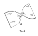
- the material is highly flexible, allowing a multiple sided cavity or parabolic shaped reflectors to be readily formed from a single piece. By reducing the seams which are inherent in a multiple piece product, total reflectance can be further enhanced.
- the material is easily die-cut, allowing each piece to be sized to the appropriate dimensions using clean and efficient methods.
- the material used in the present invention demonstrates excellent reflectant properties even at relatively thin (e.g., ⁇ 1 mm) thicknesses, making the material lighter, reducing material volume, and being less expensive to employ than presently available materials.
- the material of the present invention lends itself to use in many applications not previously available.
- the material of the present invention is very stable over time with respect to a wide range of environmental conditions, making it ideally suitable for applications requiring long life stability in harsh environmental conditions.
- the material of the present invention has extremely low UV-visible light absorption which enables the material to remain virtually unaffected when exposed to these often harmful wavelengths.
- the present invention relates to surfaces used to reflect light, and particularly to highly light reflectant surfaces in the ultraviolet and visible wavelengths for photoinduction chambers.
- Photoinduction chamber is meant to describe any volume of space where light energy is reflected in a controlled manner in order to effectuate a physical, chemical, or biological change due to light energy impinging upon some surface.
- a photoinduction chamber would typically include one or more UV and/or visible light sources and a reflector for redirecting light towards a subject material.
- the chamber can either be partially or totally enclosed to contain or direct the light energy.
- batch type processes employ a totally enclosed chamber whereas continuous processes would normally utilize a partially enclosed chamber.
- UV-visible light 250 to 750 nm wavelength
- IR light radiation 750 to greater than 2500 nm wavelength
- the material of the present invention may be tailored to modify reflectance in particular bands of light energy through the use of coatings, fillers, or similar materials or modification of ePTFE structure.
- PTFE reflectant material commercially available today is that sold under the trademark SPECTRALON by Labsphere, Inc., of North Sutton, NH.
- This material comprises a granular polytetrafluoroethylene material that is lightly packed and then molded into a rigid block.
- Figure 1 is a scanning electron micrograph (SEM) of a surface of a 1/2 inch thick reflectant sheet of SPECTRALON material. While this material provides good reflectivity of visible and near IR light, its reflectance diminishes in the UV wavelengths below 325 nanometers and it has a number of drawbacks that constrain its use.
- the present invention employs a distinctly different material comprising an expanded polytetrafluoroethylene (PTFE), such as that made in accordance with United States Patents 3,953,566, 3,962,153, 4,096,227, 4,187,390, and 4,902,423, all incorporated by reference.
- PTFE polytetrafluoroethylene
- This expanded PTFE matenal comprises a microporous structure of microscopic polymeric fibrils (i.e., threadlike elements) interconnecting polymeric nodes (i.e., particles from which fibrils emerge)
- the structure of a biaxially expanded example of this material is shown in the SEM of Figure 2.
- This material 10 comprises polymeric nodes 12 and numerous fibrils 14 extending from the nodes 12. As can be seen, numerous microporous voids 16 are provided within the material 10.
- expanded PTFE is intended to include any PTFE material having a node and fibril structure, including in the range from a slightly expanded structure having fibrils extending from relatively large nodes of polymeric or other material, to an extremely expanded structure having fibrils merely intersect with one another at nodal points.
- Expanded PTFE has a number of important properties that make it particularly suitable as a reflectant surface of the present invention.
- PTFE is a highiy inert material that is hydrophobic. Accordingly, the material is resistant to ooth water and a wide variety of other materials that could damage some other reflectant surfaces. Additionally. by expanding PTFE in the manner taught by United States Patent 3,953,566 to form the node and fibril structure, the material undergoes a significant increase in tensile strength and becomes highly flexible. Moreover, while packed granular based PTFE material provides good reflectant properties, it has been discovered that the node and fibril structure of expanded PTFE provides a much higher reflectance property.
- a preferred reflectant material of the present invention is made in the following manner.
- a fine powder PTFE resin is blended with a lubricant, such as odorless mineral spirits, until a compound is formed.
- the volume of lubricant used should be sufficient to lubricate primary oarticies of the PTFE resin so as to minimize the potential of the shearing of the particles prior to extruding.
- the compound is then compressed into a billet and extruded. such as through a ram type extruder, to form a coherent sneet of extrudate.
- the lubricant may then be removed, such as through volatilization, and the dry coherent extrudate sheet is expanded rapidly in at least one direction 1.1 to 50 times its original length (with 1.5 to 2.5 times being preferred). Expansion may be accomplished by passing the dry coherent extrudate over a series of rotating heated rollers or heated plates at a temperature of between 100 and 325°C, such as through the method taught in United States Patent 3,953,566. Altematively, the extruded sheet may be expanded in the manner described in United States Patent 4,902,423 to Bacino, prior to removal of the lubricant.
- the material may be further expanded at a ratio of 1:1.1 to 50:1 (with 5:1 to 35:1 being preferred) to form a final microporous sheet.
- the sheet is biaxially or multi-axially expanded so as to increase its strength in both its longitudinal and transverse directions.
- the material may be subjected to an amorphous locking step by exposing it to a temperature in excess of 340°C.
- the material of the present invention is preferably made in the form of sheets, which, due to their inherent flexibility, may be formed into a wide variety of other shapes as desired, such as tubes, strips, convex or concave structures, etc. Additionally, to address particular applications, the material of the present invention may likewise be extruded or otherwise formed into continuous tubes, rods (i.e., cylinders), rectangles, uneven shapes, and other structures that may be of interest.
- Sheets made from the above processing steps can be produced in thicknesses ranging from, but not limited to, 0.01 mm to 12 mm or more. Sheets can be subsequently layered upon themselves and subjected to temperatures ranging from 300°C to 400°C while applying sufficient pressures to bond the layers together.
- the present invention demonstrates extremely high reflectivity.
- the reflectant material of the present invention exhibited substantially higher reflectivity.
- the material exhibits a very predictable, flat-line reflective response across a wide spectrum of light.
- the reflectant material 10 of the present invention is highly malleable, moldable, and flexible, allowing it to be bent, twisted, curved, or otherwise formed into any suitable shape.
- the reflectant material of the present invention is a dramatic improvement over previously available other reflectant materials, such as polished aluminum that must be machined into desired shapes.
- a host of different non-planar shapes can be formed with minimal effort.
- These types of thin, flexible, formable materials having a high reflectivity e.g., 90 to 95% to 99% or more
- the base material of PTFE is not subject to corrosion from moisture and chemical elements. Where these environmental conditions are present it would present yet another advantage over polished aluminum.
- the present invention may comprise single or multiple layers of expanded PTFE, or may comprise a laminate of one or more layers of expanded PTFE and a backing support material. Since the expanded PTFE membrane alone tends to be susceptible to stretching and distortion, for some applications it may be preferred that the membrane be mounted to a support layer, such as through lamination to a flexible woven or non-woven material, that will help maintain the shape of the image layer during use.
- a support layer is applied by applying an adhesive material, such as moisture curable polyurethane or solvated polyurethane, to the expanded PTFE membrane and then applying the adhesive-coated expanded PTFE membrane to a flexible backing material (e.g., polyester, polypropylene, MYLAR®, KEVLAR®, nylon, etc.).
- the two materials can then be bonded to each other under applied pressure, such as by rolling the material between one or more pairs of nip rollers.
- a moisture curable polyurethane adhesive to bond an expanded PTFE membrane to a woven fabric, such as nylon
- the application of a pressure of about 1150 g per linear meter is sufficient to bond the materials together.
- the materials are then allowed to moisture cure for a period of about 48 hours before use.
- an expanded PTFE sheet can be bonded to a rigid support material and then formed as a composite into shapes, such as parabolic or ellipsoidal domes.
- One suitable method for such forming techniques comprises using vacuum forming devices.
- a reflectant material of the present invention was prepared in the following manner:
- a fine powder PTFE resin was combined in a blender with odorless mineral spirits (ISOPAR K available from Exxon Corp.) until a compound was obtained.
- the volume of mineral spirits used per gram of fine powder PTFE resin was 0.275 cc/gm.
- the compound was compressed into a billet and extruded through a 1.14 mm gap die attached to a ram type extruder to form a coherent extrudate. A reduction ratio of 47:1 was used.
- the odorless mineral spirit was volatilized and removed, and the dry coherent extrudate was expanded uniaxially in the longitudinal direction 4.0 times its original length by passing the dry coherent extrudate over a series of rotating heated rollers at a temperature of 300°C.
- the sheet was subsequently subjected to an amorphous locking step by passing the sheet over a series of rotating heated rollers at a temperature of 385°C such that the material was in contact with the rollers for about 12 seconds.
- This material formed a relatively course expanded structure such as that shown in Figure 3.
- the volume of mineral spirits used per gram of fine powder PTFE resin was 0.297 cc/gm.
- the compound was compressed into a billet and extruded through a 1.52 mm gap die attached to a ram type extruder to form a coherent extrudate.
- a reduction ratio of 70:1 was used.
- the odorless mineral spirit was volatilized and removed.
- Three layers of the dry coherent extrudate were then stacked and expanded uniaxially in the longitudinal direction 4.6 times its original length by passing the dry coherent extrudate over a series of rotating heated rollers at a temperature of 310°C.
- the sheet was subsequently subjected to an amorphous locking step by passing the sheet over a series of rotating heated rollers at a temperature of 385°C for about 40 seconds.
- a sheet of the present invention was produced in the following manner:
- a fine powder PTFE resin was combined with an odorless mineral spirit.
- the volume of mineral spirits used per gram of fine powder PTFE resin was 0.275 cc/gm. This mixture is aged below room temperature to allow for the mineral spirits to become uniformly distributed within the PTFE fine powder resin. This mixture was compressed into a billet and extruded at approximately 8300 kPa through a 0.71 mm gap die attached to a ram type extruder to form a coherent extrudate. A reduction ratio of 75:1 was used.
- the extrudate is then rolled down between two metal rolls which were heated to between 30-40°C.
- the final thickness after roll down was 0.20 mm.
- the material was transversely expanded at a ratio of 3:1 and then the mineral spirits were removed from the extrudate by heating the mass to 240°C (i.e., a temperature where the mineral spirits were highly volatile).
- the dried extrudate was transversely expanded at 150°C at a ratio of 3.5:1. After expansion, the sheet was amorphously locked at greater than 340°C and cooled to room temperature. This material forms a relatively fine expanded structure such as that shown in Figure 2.
- Layered expanded PTFE material similar to that described in Example 3 above is commercially available from W. L. Gore & Associates, Inc., Elkton, MD, as a sheet gasket material under the trademark GORE-TEX GR® sheet gasketing. This material is available in different thicknesses (i.e., constituting different number of layers formed into cohesive sheets).
- GORE-TEX GR® sheet gasketing This material is available in different thicknesses (i.e., constituting different number of layers formed into cohesive sheets).
- Sample 1 A composite sheet comprising about 15 layers of expanded PTFE sheets with the following properties: Thickness 0.5 mm Density 0.60 g/cc
- Sample 2 A composite sheet comprising about 25 layers of expanded PTFE sheets with the following properties: Thickness 1.0 mm Density 0.57 g/cc
- Sample 3 A composite sheet comprising about 60 layers of expanded PTFE sheets with the following properties: Thickness 2.2 mm Density 0.61 g/cc
- Sample 4 A composite sheet comprising about 85 layers of expanded PTFE sheets with the following properties: Thickness 3.4 mm Density 0.59 g/cc
- Sample 5 A composite sheet comprising about 150 layers of expanded PTFE sheets with the following properties: Thickness 6.2 mm Density 0.51 g/cc
- Sample 6 A gasket tape comprising a single layer of relatively course expanded PTFE with the following properties: Thickness 1.0 mm Density 0.50 g/cc
- Sample 7 A gasket tape comprising a single layer of relatively course expanded PTFE with the following properties: Thickness 3.3 mm Density 0.66 g/cc
- Example 3 Several single layers as described in Example 3 were then stacked upon itself without pressure and heat to form a composite of two, three, and four layered material. These examples are herein designated as Samples 8, 9, and 10 respectively.
- Sample 8 A composite sheet comprising 2 layers of expanded PTFE sheets with the following properties: Thickness 0.07 mm Density 0.61 g/cc
- Sample 9 A composite sheet comprising 3 layers of expanded PTFE sheets with the following properties: Thickness 0.11 mm Density 0.61 g/cc
- Sample 10 A composite sheet comprising 4 layers of expanded PTFE sheets with the following properties: Thickness 0.15 mm Density 0.61 g/cc
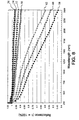
- a 2 inch by 2 inch swatch from each of Samples 1 through 7 was placed in a CARY 5E Spectrophotometer with a Labsphere integrating sphere. The spectral range measured was 175 nm to 2500 nm. Data below 250 nm was not reported due to the unreliability of the standard material below this value. All measurements were made in the double-beam mode with the same working standard in the sphere's reference reflectance port.
- the reflectance standard used was of SPECTRALON material, Labsphere Serial Number SRS-99-010-8111-A. Photomultiplier detection was used below 800 nm and lead sulfide detection was used above 800 nm. All measurements were normalized with respect to the baseline of the system. This data is then corrected by multiplying it by the correction factors supplied with the reflectance standard. This data was then averaged and plotted.
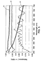
- the graph of Figure 5 records the reflectance verses light wavelength of one sample of the present invention as compared with three commercially available reflectant materials.
- Line 18 is the performance of the material of Sample 4 of the present invention.
- Line 20 is a 3 mm thick commercially available reflectant material called SPECTRALON available from Labsphere, Inc., North Sutton, NH.
- Line 22 is a 3.2 mm thick another PTFE reflectant material called FLUOROGLAS 513892 T100 125 available from Allied-Signal Inc., Hoosick Falls, NY.
- Line 24 is a reflectant material of polished aluminum called BRITELITE available from Aquarium Products, Glen Burnie, MD. As can be seen, at all wavelengths of the UV-visible light tested, the reflectant material of the present invention demonstrated markedly higher reflectivity than the commercially available reflectant materials.
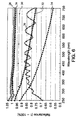
- the graph of Figure 6 records the reflectance verses light wavelength of different thicknesses of inventive material compared to other reflective materials.
- Lines 26, and 28 represent the performance of inventive samples 1 and 2, respectively.
- Line 30 represents the reflectance performance of 1 mm thick SPECTRALON as reported in the Labsphere technical literature.
- Lines 32 and 34 represent the reflectance of 1.6 mm and 0.8 mm thick conventional skived PTFE available from McArnold-Desco of Wilmington, DE.
- Line 36 is a reflectant material of polished aluminum called BRITELITE available from aquarium Products, Glen Burnie, MD. This graph demonstrates that even at thinner cross sections, the inventive material outperforms the reflectant aluminum and even other thicker cross section PTFE reflectant materials in all wavelengths tested in the UV-visible light spectrum.
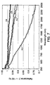
- the graph of Figure 7 records the reflectance verses light wavelength of four samples with similar densities of expanded PTFE material of the present invention. Of the four samples, there are two different thickness levels represented, with a coarse and fine structure material at each level. Lines 40 and 42 represent Samples 6 and 7, respectively, each with a relatively coarse structure characterized by large nodes and thick fibrils. Lines 44 and 46 represent Samples 2 and 4, respectively, each having a relatively fine structure characterized by small nodes and fine fibrils.
- the finer structure material demonstrated much higher reflectivity than the coarser structure material at all wavelengths tested.
- Sample 2 with a thickness of 1.0 mm was substantially more reflective than Sample 6 with the same thickness of 1.0 mm.
- the graph of Figure 8 represents the reflectance of various thicknesses of the inventive material.
- Lines 50, 52, 54, and 56 represent the reflectance of samples 1, 2, 3, and 4 respectively from Example 4.
- Lines 58, 60, and 62 represent the reflectance of samples 8, 9, and 10 respectively from Example 5.
- materials of similar structure increase in reflectance as their thickness increases. With decreasing thickness there is a greater loss of reflectance towards the higher wavelengths (in the infrared region of 750 to 2500 nanometers).
- the substrate that is being cured may not be able to withstand the relatively high infrared heat that can be delivered from the UV curing lamps.
- the material of the present invention may be modified through processing or additional fillers and/or coatings to provide high reflectance in one range of the light spectrum and absorbence in another range of the spectrum.
- coatings and or absorbers in the reflector to minimize the reflected IR energy in the form of heat that radiates from the reflector towards the substrate.
- suitable fillers for modifying the reflective properties of the inventive material include carbon, titanium dioxide, and a wide range of pigments.
- Another method for controlling the heat dissipation of the inventive reflecting material is by the addition of fillers and or coatings that modify the thermal conductance of the material.
- Boron nitride is an example of one such filler which may be used to increase the thermal conductivity while having little effect on reflectance
- Other examples of fillers which increase the thermal conductivity include silicon oxide, alumina, zinc, graphite, zinc oxide, etc.
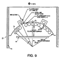
- a typical chamber 70 is described in ASTM test method D4674 and is shown in Figure 9.
- the test chamber 70 is generally constructed of UV reflective aluminum 72 with a clear, chromate conversion coating.
- An arched reflector 74 with a radius of 330 mm serves as the chamber roof.
- a test drawer 76 made also of reflective aluminum is place 140 mm from the lower edge of a center bulb 78. Samples for evaluation are placed on the sample drawer 76 for a specified amount of exposure time.
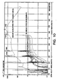
- the typical source light spectral energy distribution of the indoor accelerated test chamber is shown in Figure 10.
- Inventive material produced in the same manner as Example 3 was used to line the top of the sample drawer 76 of the chamber.
- This composite sheet comprising about 20 layers of expanded PTFE sheets was measured to be 0.8 mm thick with a density of about 0.6 g/cc.
- Measurements of ultraviolet and visible light levels were taken both before and after introducing the inventive material lining the sample tray The ultraviolet light level increased approximately 24% over the original aluminum surface. The visible light level increase was measured to be 30%. This procedure was repeated three times. The percentage increase remained constant for all three tests.
- the inventive material is employed in a UV curing lamp system.
- the system used was a model F300 Ultraviolet Lamp System supplied by Fusion Systems Corporation, Rockville, MD.
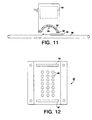
- the system as shown in Figure 11 incorporates a magnetron 80, a polished aluminum waveguide and reflector 82, a electrodeless mercury vapor lamp 84, and a conveyor belt 86.
- the photoinduction chamber in this application can be identified as the partially enclosed area beneath the reflector and including the reflector and the portion of the conveyor belt under the reflector.
- the system operates as follows:
- the magnetron 80 is a diode vacuum tube in which the flow of electrons is controlled by an externally applied magnetic field to generate power at microwave frequencies. The microwave energy is directed towards the electrodeless mercury vapor lamp 84.
- the lamp is a closed quartz tube containing a small amount of mercury and an easily ionized starter gas.
- the microwave energy in the form of a high frequency and high intensity electric field excites the gas inside the bulb to extremely high energy levels, vaporizing the mercury, and causing the molecules in the resulting plasma to emit their characteristic wavelengths of light.
- the peak wavelength of the lamp used was 365 nanometers.
- Light from the lamp emits in all directions, with the portion impinging upon the reflector being redirected back towards the area of the conveyor belt within the photoinduction chamber. Samples are placed upon the conveyor belt which transports them through the photoinduction chamber. Curing speeds of the sample are a function of the light energy impinging upon the sample and the speed of the conveyor belt.
- the waveguide/reflector 82 is further detailed in Figure 12.
- the polished aluminum waveguide/reflector 82 incorporates a series of openings in the form of holes 90 and slots 92. The main purpose for these openings is to transmit and guide the microwave energy from the magnetron to the lamp. These openings can also be utilized to provide additional air circulation for cooling of the lamp.
- a test was conducted by first establishing the light output of the system. This was accomplished by utilizing a light sensor 94, such as an IL 390B LIGHT BUG available from International Light, Inc., Newbury Port, MA.
- the light sensor 94 records the total cumulative light energy exposure in milijoules/cm 2 .
- the light sensor 94 was placed on the conveyor belt at a constant speed and run through the photoinduction chamber five times to establish a base line of the system.
- inventive material 88 such as described in sample 4 of Example 4, was attached to the surface of the polished aluminum waveguide/reflector 82, effectively replacing the reflector surface.
- This inventive material 88 had only a fraction of the openings as compared to the aluminum waveguide/reflector 82 such that a portion of the openings in the aluminum reflector were covered by the inventive reflective material.
- the relatively small fraction of openings in the expanded PTFE reflector were solely for the purpose of cooling air circulation.
- the light sensor 94 was again run through the system another five times at the same conditions as described above.
- the inventive material 88 was then removed and the light sensor 94 was again run through the system another five times at the same conditions.
- the calculated percent increase of total cumulative energy measured using the inventive material as a reflector was 14.3% higher than that of the standard polished aluminum reflector.
- a microwave guiding material such as metal with an expanded PTFE reflector.
- Certain methods include the thin coating of a metal material on an expanded PTFE substrate, i.e., vacuum deposition, sputter coating, lamination, etc., which can provide a flexible composite.
- Other embodiments could combine a rigid metal waveguide with the expanded PTFE reflector through adhesives or mechanical fasteners to create a relatively rigid composite reflector.
Landscapes
- Physics & Mathematics (AREA)
- Engineering & Computer Science (AREA)
- General Physics & Mathematics (AREA)
- Optics & Photonics (AREA)
- Chemical & Material Sciences (AREA)
- General Engineering & Computer Science (AREA)
- Nonlinear Science (AREA)
- Manufacturing & Machinery (AREA)
- Mathematical Physics (AREA)
- Medicinal Chemistry (AREA)
- Polymers & Plastics (AREA)
- Organic Chemistry (AREA)
- Materials Engineering (AREA)
- Health & Medical Sciences (AREA)
- Crystallography & Structural Chemistry (AREA)
- Chemical Kinetics & Catalysis (AREA)
- Laminated Bodies (AREA)
- Vessels And Coating Films For Discharge Lamps (AREA)
- Physical Or Chemical Processes And Apparatus (AREA)
- Road Signs Or Road Markings (AREA)
- Treatments Of Macromolecular Shaped Articles (AREA)
Applications Claiming Priority (3)
| Application Number | Priority Date | Filing Date | Title |
|---|---|---|---|
| US569411 | 1984-01-09 | ||
| US08/569,411 US5689364A (en) | 1995-01-06 | 1995-12-06 | Light reflectant surface for photoinduction chambers |
| PCT/US1996/016142 WO1997020882A1 (en) | 1995-12-06 | 1996-10-09 | Light reflectant surface for photoinduction chambers |
Publications (2)
| Publication Number | Publication Date |
|---|---|
| EP0865460A1 EP0865460A1 (en) | 1998-09-23 |
| EP0865460B1 true EP0865460B1 (en) | 2000-02-02 |
Family
ID=24275338
Family Applications (1)
| Application Number | Title | Priority Date | Filing Date |
|---|---|---|---|
| EP96934130A Expired - Lifetime EP0865460B1 (en) | 1995-12-06 | 1996-10-09 | Light reflectant surface for photoinduction chambers |
Country Status (7)
| Country | Link |
|---|---|
| US (1) | US5689364A (ja) |
| EP (1) | EP0865460B1 (ja) |
| JP (1) | JP4271727B2 (ja) |
| AU (1) | AU712860B2 (ja) |
| CA (1) | CA2236803C (ja) |
| DE (1) | DE69606553T2 (ja) |
| WO (1) | WO1997020882A1 (ja) |
Families Citing this family (26)
| Publication number | Priority date | Publication date | Assignee | Title |
|---|---|---|---|---|
| US5982542A (en) * | 1995-01-06 | 1999-11-09 | W. L. Gore & Associates, Inc. | High light diffusive and low light absorbent material and method for making and using same |
| US6015610A (en) * | 1995-01-06 | 2000-01-18 | W. L. Gore & Associates, Inc. | Very thin highly light reflectant surface and method for making and using same |
| US5936727A (en) * | 1997-04-24 | 1999-08-10 | Foss Nirsystems, Inc. | Wavelength standard |
| US5982548A (en) * | 1997-05-19 | 1999-11-09 | W. L. Gore & Associates, Inc. | Thin light reflectant surface and method for making and using same |
| US5976686A (en) * | 1997-10-24 | 1999-11-02 | 3M Innovative Properties Company | Diffuse reflective articles |
| US6214362B1 (en) * | 1999-11-24 | 2001-04-10 | Darren L. Page | Cosmetic pad for removing low tension substances and applying cosmetics |
| US6437861B1 (en) | 2000-02-16 | 2002-08-20 | Expo Photonic Solutions Inc. | Compact light integration interface |
| WO2004050130A1 (en) * | 2002-11-27 | 2004-06-17 | Novatron, Inc. | Uv flux multiplication system for sterilizing air, medical devices and other materials |
| US7875247B2 (en) * | 2002-11-27 | 2011-01-25 | Novatron, Inc. | UV flux multiplication system for sterilizing air, medical devices and other materials |
| US20050115498A1 (en) * | 2003-09-23 | 2005-06-02 | Ingram Michael W. | Reflector for UV curing systems |
| US20070200337A1 (en) * | 2006-02-27 | 2007-08-30 | Aaron Henry Johnson | Method for creating a decoy exhibiting realistic spectral reflectance |
| TW200740474A (en) * | 2006-04-25 | 2007-11-01 | Bing-Yang Yao | Device capable of sterilizing completely |
| US20080269844A1 (en) * | 2007-04-30 | 2008-10-30 | Logslett Kimberly D | Reflective Crib Liner |
| US8490321B1 (en) | 2009-11-04 | 2013-07-23 | Scott A. Butz | UV reflective fishing lure system |
| US8854734B2 (en) * | 2009-11-12 | 2014-10-07 | Vela Technologies, Inc. | Integrating optical system and methods |
| US8426800B2 (en) | 2010-09-09 | 2013-04-23 | Vela Technologies, Inc. | Integrating optical systems and methods |
| US9093258B2 (en) | 2011-06-08 | 2015-07-28 | Xenex Disinfection Services, Llc | Ultraviolet discharge lamp apparatuses having optical filters which attenuate visible light |
| US9165756B2 (en) * | 2011-06-08 | 2015-10-20 | Xenex Disinfection Services, Llc | Ultraviolet discharge lamp apparatuses with one or more reflectors |
| US11000622B2 (en) | 2012-07-27 | 2021-05-11 | Aeroclean Technologies, Llc | UV sterilization apparatus, system, and method for forced-air patient heating systems |
| US20160038624A1 (en) * | 2012-07-27 | 2016-02-11 | Mark D. Krosney | Uv sterilization apparatus, system, and method for forced-air patient heating systems |
| GB2558367B (en) | 2014-09-18 | 2019-07-31 | Xenex Disinfection Services Llc | Room and area disinfection apparatuses utilizing pulsed light |
| KR102612777B1 (ko) | 2017-08-31 | 2023-12-13 | 에어로클린 테크놀로지스, 엘엘씨 | 공기 처리 시스템 및 방법 |
| KR102595821B1 (ko) * | 2018-05-02 | 2023-10-30 | 서울바이오시스 주식회사 | 발광 소자 패키지 |
| CN111200049A (zh) * | 2018-05-02 | 2020-05-26 | 首尔伟傲世有限公司 | 发光元件封装件 |
| US11850336B2 (en) | 2020-05-22 | 2023-12-26 | Molekule Group, Inc. | UV sterilization apparatus, system, and method for aircraft air systems |
| US11779675B2 (en) | 2020-10-19 | 2023-10-10 | Molekule Group, Inc. | Air sterilization insert for heating, ventilation, and air conditioning (HVAC) systems |
Family Cites Families (22)
| Publication number | Priority date | Publication date | Assignee | Title |
|---|---|---|---|---|
| SE392582B (sv) * | 1970-05-21 | 1977-04-04 | Gore & Ass | Forfarande vid framstellning av ett porost material, genom expandering och streckning av en tetrafluoretenpolymer framstelld i ett pastabildande strengsprutningsforfarande |
| US4035085A (en) * | 1973-06-29 | 1977-07-12 | Ppg Industries, Inc. | Method and apparatus for comparing light reflectance of a sample against a standard |
| US4096227A (en) * | 1973-07-03 | 1978-06-20 | W. L. Gore & Associates, Inc. | Process for producing filled porous PTFE products |
| DE2347015C2 (de) * | 1973-09-14 | 1985-12-12 | Schering AG, 1000 Berlin und 4709 Bergkamen | Neue Pyrazolyloxyessigsäurederivate, Verfahren zu ihrer Herstellung und diese enthaltende Mittel |
| JPS5936837B2 (ja) * | 1977-04-05 | 1984-09-06 | 株式会社東芝 | 光半導体装置 |
| US4571448A (en) * | 1981-11-16 | 1986-02-18 | University Of Delaware | Thin film photovoltaic solar cell and method of making the same |
| FR2530873A1 (fr) * | 1982-03-17 | 1984-01-27 | Ozil Maurice | Dispositif de reperage de positions de cartes de circuits imprimes par rapport a leurs connecteurs |
| US4523319A (en) * | 1983-05-10 | 1985-06-11 | Brown University | Laser tape systems |
| US4764932A (en) * | 1985-12-13 | 1988-08-16 | Continental Laser Corporation | Ion laser having direct liquid cooling of segmented discharge tube |
| US4718974A (en) * | 1987-01-09 | 1988-01-12 | Ultraphase Equipment, Inc. | Photoresist stripping apparatus using microwave pumped ultraviolet lamp |
| US4802186A (en) * | 1987-07-06 | 1989-01-31 | Hughes Aircraft Company | High reflectance laser resonator cavity |
| US4912720A (en) * | 1988-10-27 | 1990-03-27 | Labsphere, Inc. | Laser cavity material |
| DE3840632A1 (de) * | 1988-12-02 | 1990-06-07 | Kempf Georg Ulrich | Streuscheibe |
| US4902423A (en) * | 1989-02-02 | 1990-02-20 | W. L. Gore & Associates, Inc. | Highly air permeable expanded polytetrafluoroethylene membranes and process for making them |
| US4994673A (en) * | 1989-06-06 | 1991-02-19 | Solon Technologies, Inc. | Ruggedized scintillation detector |
| EP0450131B1 (en) * | 1990-04-06 | 1995-08-02 | New Japan Radio Co., Ltd. | Electrodeless microwave-generated radiation apparatus |
| US5037618A (en) * | 1990-04-13 | 1991-08-06 | Peroxidation Systems, Inc. | Oxidation chamber |
| US5116115A (en) * | 1990-05-09 | 1992-05-26 | Wyko Corporation | Method and apparatus for measuring corneal topography |
| KR950006318B1 (ko) * | 1990-07-16 | 1995-06-13 | 미쓰이세끼유 가가꾸고오교오 가부시끼가이샤 | 확산반사체(diffusion reflector) 및 그를 이용한 고체레이저 장치 |
| AU644518B2 (en) * | 1991-04-29 | 1993-12-09 | Labsphere, Inc. | Integrating sphere for diffuse reflectance and transmittance measurements and the like |
| JPH07235714A (ja) * | 1994-02-23 | 1995-09-05 | Mitsubishi Electric Corp | 固体レーザ装置 |
| US5596450A (en) * | 1995-01-06 | 1997-01-21 | W. L. Gore & Associates, Inc. | Light reflectant surface and method for making and using same |
-
1995
- 1995-12-06 US US08/569,411 patent/US5689364A/en not_active Expired - Lifetime
-
1996
- 1996-10-09 AU AU72622/96A patent/AU712860B2/en not_active Expired
- 1996-10-09 JP JP51299597A patent/JP4271727B2/ja not_active Expired - Lifetime
- 1996-10-09 WO PCT/US1996/016142 patent/WO1997020882A1/en active IP Right Grant
- 1996-10-09 EP EP96934130A patent/EP0865460B1/en not_active Expired - Lifetime
- 1996-10-09 CA CA002236803A patent/CA2236803C/en not_active Expired - Lifetime
- 1996-10-09 DE DE69606553T patent/DE69606553T2/de not_active Expired - Lifetime
Also Published As
| Publication number | Publication date |
|---|---|
| AU712860B2 (en) | 1999-11-18 |
| EP0865460A1 (en) | 1998-09-23 |
| JP4271727B2 (ja) | 2009-06-03 |
| DE69606553D1 (de) | 2000-03-09 |
| US5689364A (en) | 1997-11-18 |
| CA2236803C (en) | 2001-04-03 |
| DE69606553T2 (de) | 2000-09-14 |
| JP2000502489A (ja) | 2000-02-29 |
| CA2236803A1 (en) | 1997-06-12 |
| WO1997020882A1 (en) | 1997-06-12 |
| AU7262296A (en) | 1997-06-27 |
Similar Documents
| Publication | Publication Date | Title |
|---|---|---|
| EP0865460B1 (en) | Light reflectant surface for photoinduction chambers | |
| JP3803377B2 (ja) | 光反射面とその製造及び使用方法 | |
| JP4260884B2 (ja) | 光再分配材料 | |
| JP3920339B2 (ja) | 背光形液晶ディスプレイ用の光反射面 | |
| US5892621A (en) | Light reflectant surface for luminaires | |
| US5982542A (en) | High light diffusive and low light absorbent material and method for making and using same | |
| EP1065439B1 (en) | Light reflectant surface in a recessed cavity substantially surrounding a compact fluorescent lamp | |
| EP0673751A2 (en) | Process for modifying surface of fluororesin product | |
| EP1105752B1 (en) | Contaminant resistant, cleanable, light reflective surface |
Legal Events
| Date | Code | Title | Description |
|---|---|---|---|
| PUAI | Public reference made under article 153(3) epc to a published international application that has entered the european phase |
Free format text: ORIGINAL CODE: 0009012 |
|
| 17P | Request for examination filed |
Effective date: 19980605 |
|
| AK | Designated contracting states |
Kind code of ref document: A1 Designated state(s): DE FR GB IT SE |
|
| 17Q | First examination report despatched |
Effective date: 19981009 |
|
| GRAG | Despatch of communication of intention to grant |
Free format text: ORIGINAL CODE: EPIDOS AGRA |
|
| GRAG | Despatch of communication of intention to grant |
Free format text: ORIGINAL CODE: EPIDOS AGRA |
|
| GRAH | Despatch of communication of intention to grant a patent |
Free format text: ORIGINAL CODE: EPIDOS IGRA |
|
| GRAH | Despatch of communication of intention to grant a patent |
Free format text: ORIGINAL CODE: EPIDOS IGRA |
|
| GRAA | (expected) grant |
Free format text: ORIGINAL CODE: 0009210 |
|
| AK | Designated contracting states |
Kind code of ref document: B1 Designated state(s): DE FR GB IT SE |
|
| REF | Corresponds to: |
Ref document number: 69606553 Country of ref document: DE Date of ref document: 20000309 |
|
| ITF | It: translation for a ep patent filed |
Owner name: BOTTI & FERRARI S.R.L. |
|
| ET | Fr: translation filed | ||
| PLBE | No opposition filed within time limit |
Free format text: ORIGINAL CODE: 0009261 |
|
| STAA | Information on the status of an ep patent application or granted ep patent |
Free format text: STATUS: NO OPPOSITION FILED WITHIN TIME LIMIT |
|
| 26N | No opposition filed | ||
| REG | Reference to a national code |
Ref country code: GB Ref legal event code: IF02 |
|
| REG | Reference to a national code |
Ref country code: FR Ref legal event code: PLFP Year of fee payment: 20 |
|
| PGFP | Annual fee paid to national office [announced via postgrant information from national office to epo] |
Ref country code: GB Payment date: 20150924 Year of fee payment: 20 |
|
| PGFP | Annual fee paid to national office [announced via postgrant information from national office to epo] |
Ref country code: FR Payment date: 20150925 Year of fee payment: 20 Ref country code: SE Payment date: 20150925 Year of fee payment: 20 |
|
| PGFP | Annual fee paid to national office [announced via postgrant information from national office to epo] |
Ref country code: DE Payment date: 20150922 Year of fee payment: 20 Ref country code: IT Payment date: 20150925 Year of fee payment: 20 |
|
| REG | Reference to a national code |
Ref country code: DE Ref legal event code: R071 Ref document number: 69606553 Country of ref document: DE |
|
| REG | Reference to a national code |
Ref country code: GB Ref legal event code: PE20 Expiry date: 20161008 |
|
| REG | Reference to a national code |
Ref country code: SE Ref legal event code: EUG |
|
| PG25 | Lapsed in a contracting state [announced via postgrant information from national office to epo] |
Ref country code: GB Free format text: LAPSE BECAUSE OF EXPIRATION OF PROTECTION Effective date: 20161008 |