EP0864529A2 - Bauelemente - Google Patents
Bauelemente Download PDFInfo
- Publication number
- EP0864529A2 EP0864529A2 EP98104017A EP98104017A EP0864529A2 EP 0864529 A2 EP0864529 A2 EP 0864529A2 EP 98104017 A EP98104017 A EP 98104017A EP 98104017 A EP98104017 A EP 98104017A EP 0864529 A2 EP0864529 A2 EP 0864529A2
- Authority
- EP
- European Patent Office
- Prior art keywords
- coupling devices
- parts
- building element
- intermediate part
- longitudinal direction
- Prior art date
- Legal status (The legal status is an assumption and is not a legal conclusion. Google has not performed a legal analysis and makes no representation as to the accuracy of the status listed.)
- Withdrawn
Links
Images

Classifications
-
- E—FIXED CONSTRUCTIONS
- E04—BUILDING
- E04C—STRUCTURAL ELEMENTS; BUILDING MATERIALS
- E04C3/00—Structural elongated elements designed for load-supporting
- E04C3/02—Joists; Girders, trusses, or trusslike structures, e.g. prefabricated; Lintels; Transoms; Braces
- E04C3/04—Joists; Girders, trusses, or trusslike structures, e.g. prefabricated; Lintels; Transoms; Braces of metal
- E04C3/08—Joists; Girders, trusses, or trusslike structures, e.g. prefabricated; Lintels; Transoms; Braces of metal with apertured web, e.g. with a web consisting of bar-like components; Honeycomb girders
- E04C3/09—Joists; Girders, trusses, or trusslike structures, e.g. prefabricated; Lintels; Transoms; Braces of metal with apertured web, e.g. with a web consisting of bar-like components; Honeycomb girders at least partly of bent or otherwise deformed strip- or sheet-like material
-
- B—PERFORMING OPERATIONS; TRANSPORTING
- B66—HOISTING; LIFTING; HAULING
- B66C—CRANES; LOAD-ENGAGING ELEMENTS OR DEVICES FOR CRANES, CAPSTANS, WINCHES, OR TACKLES
- B66C23/00—Cranes comprising essentially a beam, boom, or triangular structure acting as a cantilever and mounted for translatory of swinging movements in vertical or horizontal planes or a combination of such movements, e.g. jib-cranes, derricks, tower cranes
- B66C23/18—Cranes comprising essentially a beam, boom, or triangular structure acting as a cantilever and mounted for translatory of swinging movements in vertical or horizontal planes or a combination of such movements, e.g. jib-cranes, derricks, tower cranes specially adapted for use in particular purposes
- B66C23/26—Cranes comprising essentially a beam, boom, or triangular structure acting as a cantilever and mounted for translatory of swinging movements in vertical or horizontal planes or a combination of such movements, e.g. jib-cranes, derricks, tower cranes specially adapted for use in particular purposes for use on building sites; constructed, e.g. with separable parts, to facilitate rapid assembly or dismantling, for operation at successively higher levels, for transport by road or rail
- B66C23/28—Cranes comprising essentially a beam, boom, or triangular structure acting as a cantilever and mounted for translatory of swinging movements in vertical or horizontal planes or a combination of such movements, e.g. jib-cranes, derricks, tower cranes specially adapted for use in particular purposes for use on building sites; constructed, e.g. with separable parts, to facilitate rapid assembly or dismantling, for operation at successively higher levels, for transport by road or rail constructed to operate at successively higher levels
- B66C23/283—Cranes comprising essentially a beam, boom, or triangular structure acting as a cantilever and mounted for translatory of swinging movements in vertical or horizontal planes or a combination of such movements, e.g. jib-cranes, derricks, tower cranes specially adapted for use in particular purposes for use on building sites; constructed, e.g. with separable parts, to facilitate rapid assembly or dismantling, for operation at successively higher levels, for transport by road or rail constructed to operate at successively higher levels with frameworks composed of assembled elements
-
- B—PERFORMING OPERATIONS; TRANSPORTING
- B66—HOISTING; LIFTING; HAULING
- B66C—CRANES; LOAD-ENGAGING ELEMENTS OR DEVICES FOR CRANES, CAPSTANS, WINCHES, OR TACKLES
- B66C23/00—Cranes comprising essentially a beam, boom, or triangular structure acting as a cantilever and mounted for translatory of swinging movements in vertical or horizontal planes or a combination of such movements, e.g. jib-cranes, derricks, tower cranes
- B66C23/62—Constructional features or details
- B66C23/64—Jibs
- B66C23/70—Jibs constructed of sections adapted to be assembled to form jibs or various lengths
-
- E—FIXED CONSTRUCTIONS
- E04—BUILDING
- E04C—STRUCTURAL ELEMENTS; BUILDING MATERIALS
- E04C3/00—Structural elongated elements designed for load-supporting
- E04C3/02—Joists; Girders, trusses, or trusslike structures, e.g. prefabricated; Lintels; Transoms; Braces
- E04C3/04—Joists; Girders, trusses, or trusslike structures, e.g. prefabricated; Lintels; Transoms; Braces of metal
- E04C2003/0486—Truss like structures composed of separate truss elements
-
- E—FIXED CONSTRUCTIONS
- E04—BUILDING
- E04C—STRUCTURAL ELEMENTS; BUILDING MATERIALS
- E04C3/00—Structural elongated elements designed for load-supporting
- E04C3/02—Joists; Girders, trusses, or trusslike structures, e.g. prefabricated; Lintels; Transoms; Braces
- E04C3/04—Joists; Girders, trusses, or trusslike structures, e.g. prefabricated; Lintels; Transoms; Braces of metal
- E04C2003/0486—Truss like structures composed of separate truss elements
- E04C2003/0491—Truss like structures composed of separate truss elements the truss elements being located in one single surface or in several parallel surfaces
Definitions
- This invention relates to a method for producing building elements, and a building element produced with this method.
- the metal profile may comprise different coupling mechanisms in the edges for coupling to other building elements or constructions.
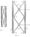
- the building elements are made from the profile by first removing most of the metal in the intermediate areas so that the pipes are periodically connected each other by a piece of metal. This recess is made so that the pipes at the edges are connected to the respective intermediate pipes at the same longitudinal, periodic positioned, while the intermediate pipes are connected to each other at longitudinal positions being hallway between the corresponding connection points between the outer pipes and the respective intermediate pipes. This way the intermediate pipes are alternately connected to each other and to the respective outer pipes. After this the profile is fastened in a bench and the outer pipes are drawn away from each other. This method provides a building element as shown in the accompanying figure 1.
- a disadvantage related to the abovementioned solution is that there are limits for have much the material may be stretched before it loses its strength, especially because the angle at which the intermediate pipes are bent exceeds a certain limit.
- the angle will normally have a limit at approximately 24 , which in its turn, in combination with other parameters, sets a limit to the width of the building elements.
- the stability and strength of the building element is given by its width.
- figure 1 shows a building element made according the known art.
- Figure 2 shows a corresponding building element made according to the present invention. As is evident from the drawing this solution provides a possibility for a larger angle between the intermediate parts 2 and the outer parts 1.
- the solution illustrated in figure 2 is made by first fastening a number of coupling devices 3,4 to two parallel, straight intermediate parts 2.
- the coupling devices are of two types in which the second coupling devices 4 make a coupling between the intermediate parts, and the first coupling devices 3 make a coupling between a intermediate part 2 and an outer part 1.
- the first coupling devices 3 are in this example positioned in pairs, so that they can connect the respective intermediate parts 2 with the corresponding outer parts 1 at the same positioned in the longitudinal direction.
- the building element is shown comprising outer parts 1 mounted thereon.
- the coupling devices are positioned alternately and with equal distances along the intermediate parts, so that one second coupling device 4 is positioned halfway between two pairs of the first coupling devices, each being positioned in a similar way between two second coupling devices 4.
- the coupling devices are fastened in their positions in any per se known way, which is not to be described here.
- the coupling devices When the coupling devices have been positioned along the required length of the intermediate parts they are placed in an adapted bench, preferably fastened to the first coupling devices 3, being adapted to pull the pairs of the first coupling devices 3 away from each other.
- Each of the intermediate parts 2 thus being bent to obtain a zigzag-shape between the first and the second coupling devices 3,4. Normally this operation will also make the building element slightly shorten than the original intermediate parts, which may be foreseen in the production.
- outer parts 1 may be mounted and fastened in a suitable way.
- the outer parts are shown in the drawings as elongated profiles, which normally will be the case when producing beams, girders or other building elements.
- Other solutions may, however, also be contemplated in which the outer elements have other forms, such as other, similar building elements or walls to be provided with a strong and lightweight building elements mounted thereon.
- Figures 3A to 3D show cross sections of each of the profiles in a preferred embodiment of the invention.
- Figure 3A shows an example of an outer part 1 comprising traces 9 for connection to the first coupling devices 3 and/or other types of constructions.
- the profile also comprises a longitudinal opening with protruding edges 5. These may constitute fastening organs for screw or the like, so that the profiles for example may be fastened on a fixed structure.
- the longitudinal opening also makes the construction lighter.
- Figure 3B shows the cross section of an intermediate part 2.
- the intermediate part is drawn with an octagonal outer profile which, when cooperating with a coupling device, may hinder twisting of the intermediate part during the stretching process.
- the intermediate part is also provided with a through-going opening with fastening organs 5 for screws.
- Figure 3C shows the first coupling device 3 with a part 6 being formed to be able to cooperate with a corresponding recess in the outer part 1.
- the shown first coupling device also has an opening 7 for receiving an intermediate part, with a shape corresponding to the outer shape of the intermediate part 2.
- the second coupling device shown in figure 3D has two openings 8 for receiving the intermediate parts 2. These openings are also adapted to the outer shape of the intermediate parts.
- One especially interesting one comprises only one intermediate part with one type of coupling devices positioned with equal distances along the intermediate part, possible alternatively oriented different ways.
- the intermediate part will make a zigzag-shape between the connection point to the outer parts.
- Other variants with three or more intermediate parts are also possible.
- the different parts of the building elements may be shaped in different types of materials, for example aluminum. Hardening and other characteristics may be chosen according to the element which is to be produced, but because a relatively large degree of deformation in the intermediate parts is required they will preferably be made slightly softer than the coupling devices. For the strength of the finished element it may, however, be advantageous if the coupling devices are somewhat deformed, so that the intermediate parts are sufficiently fastened to the coupling devices.
Landscapes
- Engineering & Computer Science (AREA)
- Architecture (AREA)
- Structural Engineering (AREA)
- Mechanical Engineering (AREA)
- Transportation (AREA)
- Civil Engineering (AREA)
- Joining Of Building Structures In Genera (AREA)
- Mutual Connection Of Rods And Tubes (AREA)
- Buildings Adapted To Withstand Abnormal External Influences (AREA)
- Vending Machines For Individual Products (AREA)
Applications Claiming Priority (2)
| Application Number | Priority Date | Filing Date | Title |
|---|---|---|---|
| NO971150A NO971150L (no) | 1997-03-12 | 1997-03-12 | Bygningselementer |
| NO971150 | 1997-03-12 |
Publications (2)
| Publication Number | Publication Date |
|---|---|
| EP0864529A2 true EP0864529A2 (de) | 1998-09-16 |
| EP0864529A3 EP0864529A3 (de) | 1999-11-03 |
Family
ID=19900488
Family Applications (1)
| Application Number | Title | Priority Date | Filing Date |
|---|---|---|---|
| EP98104017A Withdrawn EP0864529A3 (de) | 1997-03-12 | 1998-03-06 | Bauelemente |
Country Status (2)
| Country | Link |
|---|---|
| EP (1) | EP0864529A3 (de) |
| NO (1) | NO971150L (de) |
Cited By (5)
| Publication number | Priority date | Publication date | Assignee | Title |
|---|---|---|---|---|
| EP1662066A1 (de) * | 2004-11-27 | 2006-05-31 | Franz Miederhoff oHG | Fachwerkträger für den mobilen Einsatz |
| NL1029406C2 (nl) * | 2005-07-01 | 2007-01-04 | Itrec Bv | Hijskraanmodule voor demontabele hijskraan. |
| WO2009035332A1 (en) * | 2007-09-10 | 2009-03-19 | Juralco As | Truss girder and method for constructing the same |
| WO2010104396A1 (en) * | 2009-03-09 | 2010-09-16 | Juralco As | Truss girder and method for constructing the same |
| CN105544862A (zh) * | 2016-01-21 | 2016-05-04 | 正太集团有限公司 | 拼接式大跨度钢桁架 |
Family Cites Families (5)
| Publication number | Priority date | Publication date | Assignee | Title |
|---|---|---|---|---|
| US2031765A (en) * | 1932-04-19 | 1936-02-25 | Thomas B Sturges | Metallic structural framework |
| US1927443A (en) * | 1933-02-09 | 1933-09-19 | Charles W Laufle | Apparatus for expanding trussed beams |
| US2464432A (en) * | 1944-11-13 | 1949-03-15 | American Steel & Wire Co | Method for securing fittings to wire structures |
| US4892438A (en) * | 1988-12-30 | 1990-01-09 | Morrison Donald R | Screed construction and method |
| DE4315779A1 (de) * | 1993-05-12 | 1994-11-17 | Bernd Klein | Tragsystem, insbesondere für Verkehrs- und Wegweiseinrichtungen |
-
1997
- 1997-03-12 NO NO971150A patent/NO971150L/no unknown
-
1998
- 1998-03-06 EP EP98104017A patent/EP0864529A3/de not_active Withdrawn
Cited By (7)
| Publication number | Priority date | Publication date | Assignee | Title |
|---|---|---|---|---|
| EP1662066A1 (de) * | 2004-11-27 | 2006-05-31 | Franz Miederhoff oHG | Fachwerkträger für den mobilen Einsatz |
| NL1029406C2 (nl) * | 2005-07-01 | 2007-01-04 | Itrec Bv | Hijskraanmodule voor demontabele hijskraan. |
| WO2009035332A1 (en) * | 2007-09-10 | 2009-03-19 | Juralco As | Truss girder and method for constructing the same |
| GB2470976A (en) * | 2007-09-10 | 2010-12-15 | Juralco As | Truss girder and method for constructing the same |
| GB2470976B (en) * | 2007-09-10 | 2013-03-06 | Juralco As | Truss girder and method for constructing the same |
| WO2010104396A1 (en) * | 2009-03-09 | 2010-09-16 | Juralco As | Truss girder and method for constructing the same |
| CN105544862A (zh) * | 2016-01-21 | 2016-05-04 | 正太集团有限公司 | 拼接式大跨度钢桁架 |
Also Published As
| Publication number | Publication date |
|---|---|
| EP0864529A3 (de) | 1999-11-03 |
| NO971150L (no) | 1998-09-14 |
| NO971150D0 (no) | 1997-03-12 |
Similar Documents
| Publication | Publication Date | Title |
|---|---|---|
| US6698155B2 (en) | Building elements and building element assemblies formed therewith | |
| US6207256B1 (en) | Space truss composite panel | |
| CA2459936A1 (en) | Building wall element | |
| US6434908B1 (en) | Method of caps fabricating rigid section bars to be articulated manually | |
| US20040139684A1 (en) | Building elements and building element assemblies formed therewith | |
| US6560938B1 (en) | Box lintel | |
| US6665992B2 (en) | Concrete construction block and method for forming the same | |
| EP2106487B1 (de) | Profilelement als trägerstruktur zum bauen von wänden | |
| JP5184589B2 (ja) | トラス材料 | |
| HU227953B1 (en) | Joist, joist assembly, and building comprising such a joist assembly | |
| US4655021A (en) | Reticular structure | |
| KR20150002715A (ko) | 철근 콘크리트 구조체에 사용되는 철근 조립체 및 전단 보강근 | |
| EP0864529A2 (de) | Bauelemente | |
| AU2005295769B2 (en) | Building panel and building structure | |
| JP2008517187A5 (de) | ||
| KR20210042550A (ko) | 가설건축물용 보강구조물 | |
| US3303627A (en) | Reinforced structural members | |
| US6237298B1 (en) | Aluminum connector hub for a steel tube | |
| EP2406434A1 (de) | Bewehrter träger und konstruktionsverfahren dafür | |
| EP0371983B1 (de) | Gitterträger | |
| JP4977901B2 (ja) | トラス材料 | |
| US761287A (en) | Concrete-and-metal structure. | |
| SU1692693A1 (ru) | Двутавровый профиль | |
| KR20000025054A (ko) | 와이어 메쉬를 이용한 합성데크플레이트 및 그제조 방법) | |
| WO1998022674A1 (en) | Method for manufacturing a lattice structure |
Legal Events
| Date | Code | Title | Description |
|---|---|---|---|
| PUAI | Public reference made under article 153(3) epc to a published international application that has entered the european phase |
Free format text: ORIGINAL CODE: 0009012 |
|
| AK | Designated contracting states |
Kind code of ref document: A2 Designated state(s): AT BE CH DE DK ES FI FR GB GR IE IT LI LU MC NL PT SE |
|
| AX | Request for extension of the european patent |
Free format text: AL;LT;LV;MK;RO;SI |
|
| PUAL | Search report despatched |
Free format text: ORIGINAL CODE: 0009013 |
|
| AK | Designated contracting states |
Kind code of ref document: A3 Designated state(s): AT BE CH DE DK ES FI FR GB GR IE IT LI LU MC NL PT SE |
|
| AX | Request for extension of the european patent |
Free format text: AL;LT;LV;MK;RO;SI |
|
| RIC1 | Information provided on ipc code assigned before grant |
Free format text: 6B 21D 47/02 A, 6E 04C 3/08 B |
|
| AKX | Designation fees paid | ||
| REG | Reference to a national code |
Ref country code: DE Ref legal event code: 8566 |
|
| STAA | Information on the status of an ep patent application or granted ep patent |
Free format text: STATUS: THE APPLICATION IS DEEMED TO BE WITHDRAWN |
|
| 18D | Application deemed to be withdrawn |
Effective date: 20000504 |