EP0864501A2 - Method and apparatus for opening a package - Google Patents
Method and apparatus for opening a package Download PDFInfo
- Publication number
- EP0864501A2 EP0864501A2 EP98301567A EP98301567A EP0864501A2 EP 0864501 A2 EP0864501 A2 EP 0864501A2 EP 98301567 A EP98301567 A EP 98301567A EP 98301567 A EP98301567 A EP 98301567A EP 0864501 A2 EP0864501 A2 EP 0864501A2
- Authority
- EP
- European Patent Office
- Prior art keywords
- package
- laser beam
- wrapper
- covering layer
- content
- Prior art date
- Legal status (The legal status is an assumption and is not a legal conclusion. Google has not performed a legal analysis and makes no representation as to the accuracy of the status listed.)
- Withdrawn
Links
Images


Classifications
-
- B—PERFORMING OPERATIONS; TRANSPORTING
- B65—CONVEYING; PACKING; STORING; HANDLING THIN OR FILAMENTARY MATERIAL
- B65B—MACHINES, APPARATUS OR DEVICES FOR, OR METHODS OF, PACKAGING ARTICLES OR MATERIALS; UNPACKING
- B65B69/00—Unpacking of articles or materials, not otherwise provided for
- B65B69/0033—Unpacking of articles or materials, not otherwise provided for by cutting
-
- B—PERFORMING OPERATIONS; TRANSPORTING
- B32—LAYERED PRODUCTS
- B32B—LAYERED PRODUCTS, i.e. PRODUCTS BUILT-UP OF STRATA OF FLAT OR NON-FLAT, e.g. CELLULAR OR HONEYCOMB, FORM
- B32B7/00—Layered products characterised by the relation between layers; Layered products characterised by the relative orientation of features between layers, or by the relative values of a measurable parameter between layers, i.e. products comprising layers having different physical, chemical or physicochemical properties; Layered products characterised by the interconnection of layers
- B32B7/04—Interconnection of layers
- B32B7/12—Interconnection of layers using interposed adhesives or interposed materials with bonding properties
-
- B—PERFORMING OPERATIONS; TRANSPORTING
- B65—CONVEYING; PACKING; STORING; HANDLING THIN OR FILAMENTARY MATERIAL
- B65D—CONTAINERS FOR STORAGE OR TRANSPORT OF ARTICLES OR MATERIALS, e.g. BAGS, BARRELS, BOTTLES, BOXES, CANS, CARTONS, CRATES, DRUMS, JARS, TANKS, HOPPERS, FORWARDING CONTAINERS; ACCESSORIES, CLOSURES, OR FITTINGS THEREFOR; PACKAGING ELEMENTS; PACKAGES
- B65D65/00—Wrappers or flexible covers; Packaging materials of special type or form
- B65D65/38—Packaging materials of special type or form
- B65D65/40—Applications of laminates for particular packaging purposes
-
- B—PERFORMING OPERATIONS; TRANSPORTING
- B32—LAYERED PRODUCTS
- B32B—LAYERED PRODUCTS, i.e. PRODUCTS BUILT-UP OF STRATA OF FLAT OR NON-FLAT, e.g. CELLULAR OR HONEYCOMB, FORM
- B32B15/00—Layered products comprising a layer of metal
- B32B15/20—Layered products comprising a layer of metal comprising aluminium or copper
-
- B—PERFORMING OPERATIONS; TRANSPORTING
- B32—LAYERED PRODUCTS
- B32B—LAYERED PRODUCTS, i.e. PRODUCTS BUILT-UP OF STRATA OF FLAT OR NON-FLAT, e.g. CELLULAR OR HONEYCOMB, FORM
- B32B7/00—Layered products characterised by the relation between layers; Layered products characterised by the relative orientation of features between layers, or by the relative values of a measurable parameter between layers, i.e. products comprising layers having different physical, chemical or physicochemical properties; Layered products characterised by the interconnection of layers
- B32B7/04—Interconnection of layers
- B32B7/06—Interconnection of layers permitting easy separation
-
- B—PERFORMING OPERATIONS; TRANSPORTING
- B65—CONVEYING; PACKING; STORING; HANDLING THIN OR FILAMENTARY MATERIAL
- B65B—MACHINES, APPARATUS OR DEVICES FOR, OR METHODS OF, PACKAGING ARTICLES OR MATERIALS; UNPACKING
- B65B25/00—Packaging other articles presenting special problems
- B65B25/14—Packaging paper or like sheets, envelopes, or newspapers, in flat, folded, or rolled form
-
- Y—GENERAL TAGGING OF NEW TECHNOLOGICAL DEVELOPMENTS; GENERAL TAGGING OF CROSS-SECTIONAL TECHNOLOGIES SPANNING OVER SEVERAL SECTIONS OF THE IPC; TECHNICAL SUBJECTS COVERED BY FORMER USPC CROSS-REFERENCE ART COLLECTIONS [XRACs] AND DIGESTS
- Y10—TECHNICAL SUBJECTS COVERED BY FORMER USPC
- Y10S—TECHNICAL SUBJECTS COVERED BY FORMER USPC CROSS-REFERENCE ART COLLECTIONS [XRACs] AND DIGESTS
- Y10S206/00—Special receptacle or package
- Y10S206/80—Chewing gum
-
- Y—GENERAL TAGGING OF NEW TECHNOLOGICAL DEVELOPMENTS; GENERAL TAGGING OF CROSS-SECTIONAL TECHNOLOGIES SPANNING OVER SEVERAL SECTIONS OF THE IPC; TECHNICAL SUBJECTS COVERED BY FORMER USPC CROSS-REFERENCE ART COLLECTIONS [XRACs] AND DIGESTS
- Y10—TECHNICAL SUBJECTS COVERED BY FORMER USPC
- Y10S—TECHNICAL SUBJECTS COVERED BY FORMER USPC CROSS-REFERENCE ART COLLECTIONS [XRACs] AND DIGESTS
- Y10S428/00—Stock material or miscellaneous articles
- Y10S428/906—Roll or coil
-
- Y—GENERAL TAGGING OF NEW TECHNOLOGICAL DEVELOPMENTS; GENERAL TAGGING OF CROSS-SECTIONAL TECHNOLOGIES SPANNING OVER SEVERAL SECTIONS OF THE IPC; TECHNICAL SUBJECTS COVERED BY FORMER USPC CROSS-REFERENCE ART COLLECTIONS [XRACs] AND DIGESTS
- Y10—TECHNICAL SUBJECTS COVERED BY FORMER USPC
- Y10T—TECHNICAL SUBJECTS COVERED BY FORMER US CLASSIFICATION
- Y10T428/00—Stock material or miscellaneous articles
- Y10T428/14—Layer or component removable to expose adhesive
- Y10T428/1438—Metal containing
- Y10T428/1443—Aluminum
-
- Y—GENERAL TAGGING OF NEW TECHNOLOGICAL DEVELOPMENTS; GENERAL TAGGING OF CROSS-SECTIONAL TECHNOLOGIES SPANNING OVER SEVERAL SECTIONS OF THE IPC; TECHNICAL SUBJECTS COVERED BY FORMER USPC CROSS-REFERENCE ART COLLECTIONS [XRACs] AND DIGESTS
- Y10—TECHNICAL SUBJECTS COVERED BY FORMER USPC
- Y10T—TECHNICAL SUBJECTS COVERED BY FORMER US CLASSIFICATION
- Y10T428/00—Stock material or miscellaneous articles
- Y10T428/14—Layer or component removable to expose adhesive
- Y10T428/1471—Protective layer
-
- Y—GENERAL TAGGING OF NEW TECHNOLOGICAL DEVELOPMENTS; GENERAL TAGGING OF CROSS-SECTIONAL TECHNOLOGIES SPANNING OVER SEVERAL SECTIONS OF THE IPC; TECHNICAL SUBJECTS COVERED BY FORMER USPC CROSS-REFERENCE ART COLLECTIONS [XRACs] AND DIGESTS
- Y10—TECHNICAL SUBJECTS COVERED BY FORMER USPC
- Y10T—TECHNICAL SUBJECTS COVERED BY FORMER US CLASSIFICATION
- Y10T428/00—Stock material or miscellaneous articles
- Y10T428/14—Layer or component removable to expose adhesive
- Y10T428/1476—Release layer
-
- Y—GENERAL TAGGING OF NEW TECHNOLOGICAL DEVELOPMENTS; GENERAL TAGGING OF CROSS-SECTIONAL TECHNOLOGIES SPANNING OVER SEVERAL SECTIONS OF THE IPC; TECHNICAL SUBJECTS COVERED BY FORMER USPC CROSS-REFERENCE ART COLLECTIONS [XRACs] AND DIGESTS
- Y10—TECHNICAL SUBJECTS COVERED BY FORMER USPC
- Y10T—TECHNICAL SUBJECTS COVERED BY FORMER US CLASSIFICATION
- Y10T428/00—Stock material or miscellaneous articles
- Y10T428/15—Sheet, web, or layer weakened to permit separation through thickness
-
- Y—GENERAL TAGGING OF NEW TECHNOLOGICAL DEVELOPMENTS; GENERAL TAGGING OF CROSS-SECTIONAL TECHNOLOGIES SPANNING OVER SEVERAL SECTIONS OF THE IPC; TECHNICAL SUBJECTS COVERED BY FORMER USPC CROSS-REFERENCE ART COLLECTIONS [XRACs] AND DIGESTS
- Y10—TECHNICAL SUBJECTS COVERED BY FORMER USPC
- Y10T—TECHNICAL SUBJECTS COVERED BY FORMER US CLASSIFICATION
- Y10T428/00—Stock material or miscellaneous articles
- Y10T428/24—Structurally defined web or sheet [e.g., overall dimension, etc.]
- Y10T428/24777—Edge feature
Definitions
- the invention relates to a method of opening a package including a content wrapped with a wrapper.
- the content may comprise a roll including a web of paper wound thereon to form multi-layers, or sheets of paper stacked into multi-layers.
- the web or sheets may be adapted to be printed or converted.
- the invention relates to the structure of the package.
- the invention further relates to an apparatus for opening the package.
- a roll R including a web of paper wound thereon to form multi-layers for example in a web-fed press for newspaper or magazine, as shown in Fig. 35 and Fig. 36.
- the roll R is wrapped with a wrapper W for transportation and storage to form a package P including the roll R therein.
- the wrapper W keeps the roll R from being damaged. Accordingly, first of all, it is required to cut the wrapper W circumferentially of the package P at the opposite end portions thereof and then cut the wrapper W axially of the package P, to open the package P.
- the roll R is taken out of the package P and mounted on the web-fed press.
- the web of paper is fed from the roll R and printed by the web-fed press.
- the operation to open the package P it is conventional to manually out the wrapper W with a knife and a bamboo spatula.
- An operator manipulates the knife at the opposite end portions of the package P to cut the wrapper W circumferentially of the package P.
- the operator then inserts the bamboo spatula between the wrapper W and the roll R at one of the opposite end portions of the package P and move the bamboo spatula axially of the package P, to out the wrapper W axially of the package P.
- the roll R is very heavy.
- the wrapper W generally comprises a wrapping paper which is durable and strong. The wrapping paper is closely fitted on the outer surface of the roll R. It is therefore troublesome to manually and conveniently cut the wrapper W with the knife and the bamboo spatula. labour and time are required. It has also been a problem that the roll R may be damaged by the bamboo spatula inserted between the wrapper W and the roll R and moved axially of the package P. It is a task of extreme difficulty to manually and conveniently cut the wrapper W to open the package P, without damage to the roll R.
- the apparatus includes a knife having a portion of T-shaped cross section and equipments for inserting the knife between the wrapper and the roll and moving the knife axially of the package, to out the wrapper axially of the package.
- the equipments are complicated and expensive. It takes much time to open the package. It has also been a problem that the knife is liable to be worn and damaged by the durable and strong wrapping paper. It is therefore required to frequently exchange the knife for new one.
- Another object of the invention is to conveniently cut the wrapper and open the package, without damage of the content.
- Another object of the invention is to conveniently cut the wrapper and open the package, without complicated and expensive equipments.
- Another object of the invention is to conveniently cut the wrapper and open the package, without taking much time.
- Another object of the invention is to conveniently cut the wrapper and open the package, without the problem relating to the wear and damage of knife.
- a method of opening a package including a content wrapped with a wrapper comprises the step of directing a laser beam to the wrapper for cutting the wrapper with the laser beam to open the package.
- the method further comprises the step of protecting the content from being damaged by the laser beam.
- a package to be opened comprises a covering layer of material having a laser beam absorptivity which is lower than that of the wrapper.
- the covering layer may be interposed between the wrapper and the content for covering the content from the laser beam to protect the content from being damaged by the laser beam.
- the material may be coated on or impregnated into the inner surface of the wrapper to form the covering layer.
- the material may be coated on or impregnated into the outer surface of the content to form the covering layer.
- the content is of multi-layers.
- the covering layer is interposed between the layers of the content adjacent to the outer surface of the content for covering the content from the laser beam to protect the content from being damaged by the laser beam.
- the material may be coated on or impregnated into at least one layer of the content adjacent to the outer surface to form the covering layer.
- the content may comprise a roll including a web of paper wound thereon to form multi-layers, or sheets of paper stacked into multi-layers.
- the web or sheets may be adapted to be printed or converted.
- the wrapper may be made of paper, plastic film or fabric.
- the covering layer may be formed of a foil of metal.
- the covering layer may extend substantially all over the circumference of the content.
- the covering layer may comprise an elongate strip.
- the package may be intended for the wrapper to be cut with the laser beam along the strip.
- the step of protecting the content comprises the step of utilizing a type of laser beam not capable of cutting the web or sheets.
- the wrapper comprises a wrapping paper having a laser beam absorptivity which is higher than that of the web or sheets with respect to the type of laser beam to cut the wrapping paper and open the package with the laser beam.
- the wrapping paper may include a material admixed thereinto and having a high absorptivity with respect to the type of laser beam.
- the method may further comprise the step of moving the package relative to the laser beam.
- the package is cylindrical.
- the step of moving the package comprises the step of rotatingly moving the package about the central axis thereof for cutting the wrapper circumferentially of the package at the opposite end portions of the package.
- the step of moving the package further comprises the step of linearly moving the package axially thereof for cutting the wrapper in the axial direction of the package.
- the step of moving the package may comprise the step of linearly moving the package axially thereof while rotatingly moving the package about the central axis thereof for cutting the wrapper spirally.
- the method further comprises the step of sweeping the laser beam over the package which is held in position.
- the step of sweeping the laser beam may comprise the step of linearly sweeping the laser beam axially of the package for cutting the wrapper in the axial direction of the package.
- an apparatus for opening a package comprising support means for supporting the package thereon at a fixed position.
- the apparatus further comprises a laser beam source for directing a laser beam to the wrapper and linearly sweeping the laser beam over the wrapper to cut the wrapper with the laser beam in the axial direction of the package.
- the apparatus further comprises guide means adapted to guide the support means for linear movement axially of the package to cut the wrapper with the laser beam in the axial direction of the package.
- the support means may include guide means for guiding the package for rotational movement about the central axis thereof on the support means while directing the laser beam to the wrapper, to cut the wrapper circumferentially of the package at the opposite end portions of the package.
- the support means may include first drive means for rotatingly moving the package about the central axis thereof on the support means while directing the laser beam to the wrapper, to cut the wrapper circumferentially of the package at the opposite end portions of the package.
- the apparatus may further comprise second drive means for linearly moving the support means axially of the package to cut the wrapper with the laser beam in the axial direction of the package.
- the apparatus may further comprise detector means for detecting the covering layer, and control means for controlling the first and second drive means in response to a signal from the detector means to direct the laser beam to the package at the position of the covering layer.
- the roll in another embodiment, includes a web of paper wound thereon and an adhesive double coated tape which includes two adhesive layers formed on the opposite sides thereof and a release agent double coated paper adhered to one of the adhesive layers, the other adhesive layer being adhered to the end of the web.
- the adhesive double coated tape further includes a covering layer of material having a laser beam absorptivity which is lower than that of the wrapper for covering the roll from the laser beam to protect the roll from being damaged by the laser beam.
- the adhesive double coated tape may be adhered to the end of the web all over the width thereof.
- an adhesive double coated tape comprising an elongate substrate. Two adhesive layers are formed on the opposite sides of the substrate. A release agent double coated paper is adhered to one of the adhesive layers. A covering layer is formed on one of the opposite sides of the release agent double coated paper, the covering layer being of material having a low absorptivity with respect to a type of laser beam.
- the covering layer may be formed on one of the opposite sides of the substrate.
- the type of laser beam may comprise CO 2 laser beam.
- the covering layer may comprise 2 foil of metal such as aluminum.
- the covering layer may be adhered to one of the opposite sides of the release agent double coated paper or the substrate.
- the covering layer may be coated on one of the opposite sides of the release agent double coated paper or the substrate.
- the covering layer may be vapour deposited on one of the opposite sides of the release agent double coated paper or the substrate.
- the adhesive double coated tape may comprise an elongate substrate of material having a low absorptivity with respect to a type of laser beam.
- the substrate may be made of metal such as aluminum.
- the elongate substrate includes a portion weakened to be torn along a straight tearing line extending longitudinally of the substrate adjacent to one edge thereof.
- the substrate is free from one of the adhesive layers at least between the tearing line and the one edge of the substrate.
- An elongate void is formed in and clear of the other adhesive layer along the tearing line.
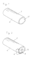
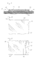
- Fig. 1 is a perspective view of a package including a content wrapped with a wrapper according to the invention, the content comprising a roll including a core about which a web of paper is wound to form multi-layers.
- Fig. 2 is a perspective view of the package of Fig. 1 in which an end paper is removed and the wrapper is partially broken to show the web and the core.
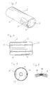
- Fig. 3 is a perspective view of a package in which the wrapper is partially broken to show a covering layer interposed between the wrapper and the roll in a preferred embodiment of the invention.
- Fig. 4 is a side view of the package of Fig. 3.
- Fig. 5 is a cross sectional view of the package of Fig. 3.
- Fig. 6 is a cross sectional view of a package including a covering layer interposed between the layers of web adjacent to the outer surface of the roll in another embodiment.
- Fig. 7 is an elevational view of an apparatus for opening the package in a preferred embodiment of the invention.
- Fig. 8 is a side view of the apparatus of Fig. 7.
- Fig. 9 to Fig. 12 are explanatory views showing the steps of opening the package in the apparatus of Fig. 7, respectively.
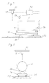
- Fig. 13 is a perspective view of a package including a content wrapped with a wrapper according to the invention, the content comprising sheets of paper stacked into multi-layers.
- Fig. 14 is a plan and sectional view of the package of Fig. 13.
- Fig. 15 is a side and sectional view of the package of Fig. 13.
- Fig. 16 is an explanatory view showing the step of opening the package in a preferred embodiment of the invention.
- Fig. 17 is an explanatory view showing the step of opening the package in another embodiment.
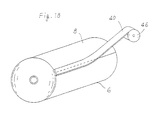
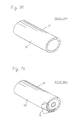
- Fig. 18 is a perspective view showing a roll including a web of paper wound thereon and an adhesive double coated tape adhered to the end of the web in a preferred embodiment of the invention.
- Fig. 19 is a cross sectional view of the roll and the adhesive double coated tape of Fig. 18.
- Fig. 20 is a plan view of the adhesive double coated tape of Fig. 19, a release agent double coated paper being removed.
- Fig. 21 is a bottom view of the adhesive double coated tape of Fig. 19.
- Fig. 22 is a bottom view of a adhesive double coated tape in another embodiment.
- Fig. 23 is a cross sectional view of an adhesive double coated tape in other embodiment.
- Fig. 24 is a cross sectional view of an adhesive double coated tape in other embodiment.
- Fig. 25 is 2 cross sectional view of an adhesive double coated tape in other embodiment.
- Fig. 26 is a cross sectional view of an adhesive double coated tape in other embodiment.
- Fig. 27 is an explanatory view showing the step of opening a package including the roll and the adhesive double coated tape.
- Fig. 28 is an explanatory view showing the release agent double coated paper removed from the adhesive layer of the adhesive double coated tape of Fig. 27.
- Fig. 29 is an explanatory view showing another web of paper adhered to the adhesive layer of the adhesive double coated tape of Fig. 28.
- Fig. 30 to Fig. 34 are explanatory views showing the steps of joining two webs of paper together, respectively.
- Fig. 35 is a perspective view of a package in prior art.
- Fig. 36 is a perspective view of the package of Fig. 35 in which an end paper is removed and a wrapper is partially broken to show a roll wrapped with a wrapper.
- Fig. 1 illustrates a package 2 including a content wrapped with a wrapper 4, according to the invention.
- the package 2 is cylindrical.
- the content comprises a roll 6 including a web of paper 8 wound thereon to form multi-layers, as shown in Fig. 2.
- the roll 6 includes a core 10 about which the web of paper 8 is wound.
- the web of paper 8 is adapted to be printed or converted.
- the wrapper 4 comprises a wrapping paper which is durable and strong.
- the wrapping paper is closely fitted on the outer surface of the roll 6 and folded along the opposite end surfaces of the roll 6.
- Two end papers 12 are adhered to the folded portions of the wrapping paper to cover the opposite end surfaces of the roll 6.
- the wrapper 4 may be made of plastic film or fabric.
- the package is intended such that a laser beam can be directed to the wrapper 4 for cutting the wrapper 4 with the laser beam.
- the package 2 is arranged to protect the roll 6 from being damaged by the laser beam.
- the package 2 includes a intercepting or covering layer 14 of material having a laser beam absorptivity which is lower than that of the wrapper 4.
- the covering layer 14 is interposed between the wrapper 4 and the roll 6 for intercepting the laser beam between the wrapper 4 and the roll 6.
- the covering layer 14 therefore covers the roll 6 from the laser beam to protect the roll 6 from being damaged by the laser beam.
- the laser beam may comprise CO 2 laser beam which can cut the wrapper 4 made of paper, plastic film or fabric.
- the covering layer 14 may be formed of a foil of metal such as aluminum. The foil may be adhered or bonded to the inner surface of the wrapper 4 to form the covering layer 14. The foil may be adhered or bonded to the outer surface of the roll 6 to form the covering layer 14.
- Metal has a laser beam absorptivity which is lower than that of the wrapper 4 with respect to CO 2 laser beam. Accordingly, the covering layer 14 can cover the roll 6 from the laser beam to protect the roll 6 from being damaged by the laser beam.
- the covering layer 14 may be formed of a material including a powdered metal admixed thereinto.
- the material may be coated on or impregnated into the inner surface of the wrapper 4 to form the covering layer 14.
- the material may be coated on or impregnated into the outer surface of the roll 6 to form the covering layer 14.
- the material may be impregnated into a fabric adhered or bonded to the inner surface of the wrapper 4 or the outer surface of the roll 6 to form the covering layer 14.
- the covering layer 14 may be interposed between the layers of the web adjacent to the outer surface of the roll 6, as shown in Fig. 6, for covering the roll 6 from the laser beam to protect the roll 6 from being damaged by the laser beam.
- the material may be coated on or impregnated into at least one layer of the roll 6 adjacent to the outer surface of the roll 6 to form the covering layer 14.
- the covering layer 14 may comprise an elongate strip which includes a straight portion extending axially of the package 2, as shown in Fig. 3 and 4.
- the strip further includes two annular portions extending circumferentially of the package 2 at the opposite end portions of the package 2.
- the package 2 is intended so that the wrapper 4 can be cut with the laser beam along the strip.
- Fig. 7 and Fig. 8 illustrate an apparatus for opening the package 2, acccording to the invention.
- the apparatus includes support means comprising a carriage 16 for supporting the package 2 thereon.
- the apparatus further includes a laser beam source 18 mounted on a frame 20 for directing a laser beam to the wrapper 4.
- the apparatus includes guide means comprising a guide bed 22 for guiding the carriage 16 for linear movement axially of the package 2.
- the carriage 16 includes wheels 24 which are fitted in and rolled along grooves formed in the guide bed 22 to guide the carriage 16 for linear movement axially of the package 2.
- the carriage 16 further includes guide means comprising rollers 26 between which the package 2 is supported for guiding the package 2 for rotational movement about the central axis thereof on the carriage 16.
- an operator can linearly move the carriage 16 along with the package 2 axially of the package 2 to position one of the opposite end portions of the package 2 below the laser beam source 18, as shown in Fig. 9 and Fig. 10.
- the operator then rotatingly moves the package 2 about the central axis thereof and operates the laser beam source 18 for directing the laser beam to the wrapper 4, to cut the wrapper 4 circumferentially of the package 2 at one of the end portions of the package 2.
- the covering layer 14 includes two annular portions extending circumferentially of the package 2 at the opposite end portions of the package 2, as described previously, so that the operator can cut the wrapper 4 with the laser beam along the annular portion of the covering layer 14. The covering layer 14 therefore covers the roll 6 from the laser beam to protect the roll 6 from being damaged by the laser beam.
- the covering layer 14 includes a straight portion extending axially of the package 2, as described previously, so that the operator can position the straight portion of the covering layer 14 below the laser beam source 18 to cut the wrapper 4 with the laser beam along the straight portion of the covering layer 14.
- the covering layer 14 therefore covers the roll 6 from the laser beam to protect the roll 6 from being damaged by the laser beam.
- annular cut lines are formed at the opposite end portions of the package 2 by the laser beam.
- a straight cut line is formed between the annular cut lines by the laser beam.
- the wrapper 4 can therefore be partially removed from the opposite end portions of the package 2 along the annular cut lines. The operator then engages a tool with the edge of the wrapper 4 formed by the straight cut line and rotatingly moves the package 2 about the central axis thereof, to peel the wrapper 4 off the roll 6.
- the apparatus therefore can conveniently cut the wrapper 4 and open the package 2, without damage of the roll 6. It does not involve complicated and expensive equipments. In addition, it does not take much time to open the package 2. It has also not a problem relating to the wear of knife.
- the roll 6 is then taken out of the package 2 and mounted on a web-fed press for newspaper or magazine.
- the web of paper 8 is fed from the roll 6 and printed by the web-fed press.
- the web of paper 8 may be converted by a paper converting machine.
- the apparatus can be arranged to automatically cut the wrapper 4 and open the package 2.
- the carriage 16 further includes first drive means not shown, but mounted on the carriage 16 and connected to the rollers 26.
- the apparatus further includes second drive means not shown, but mounted on the carriage 16 and connected to the wheels 24.
- the apparatus includes detector means 28 comprising a metal sensor for detecting the covering layer 14, and control means 30 connected to the laser beam source 18, the first and second drive means and the detector means 28.
- the control means 30 controls the first and second drive means in response to a signal from the detector means 28 in such a way that the wheels 24 are firstly rotatingly driven by the second drive means to linearly move the carriage 16 axially of the package 2 to position one of the opposite end portions of the package 2 below the laser beam source 18.
- the rollers 26 are then rotatingly driven by the first drive means to rotatingly move the package 2 about the central axis thereof.
- the laser beam source 18 directs the laser beam to the wrapper 4 to cut the wrapper 4 circumferentially of the package 2 at one of the end portions of the package 2.
- the rollers 26 cooperate with the first drive means, the detector means 28 and the control means 30 to position the straight portion of the covering layer 14 below the laser beam source 18.
- the wheels 24 are then rotatingly driven by the second drive means to linearly move the carriage 16 axially of the package 2 while directing the laser beam to the wrapper 4, to cut the wrapper 4 with the laser beam in the axial direction of the package 2.
- the rollers 26 are rotatingly driven again by the second drive means to cut the wrapper 4 circumferentially of the package 2 at the other end portion of the package 2. This can automatically cut the wrapper 4 and open the package 2.
- the wheels 24 and the rollers 26 may be rotatingly moved, to linearly move the package 2 axially thereof while rotatingly moving the package 2 about the central axis thereof for cutting the wrapper 4 spirally.
- the covering layer 14 may include a spiral portion extending axially of and about the package 2 to cut the wrapper 4 with the laser beam along the spiral portion of the covering layer 14.
- the covering layer 14 may extend substantially all over the circumference of the roll 6.
- the apparatus may be arranged to sweep the laser beam over the package 2 which is held in position, to thereby open the package 2.
- the apparatus may be arranged to rotatingly move the package 2 about the central axis thereof relative to the laser beam for cutting the wrapper 4 circumferentially of the package 2 at the opposite and portions of the package 2, and then linearly sweep the laser beam axially of the package for cutting the wrapper 4 in the axial direction of the package 2.
- a package 32 includes a content wrapped with a wrapper 34, the content comprising sheets of paper 36 stacked into multi-layers.
- the sheets of paper 36 are adapted to be printed or converted.
- the package 32 further includes a covering layer 38 of material having a laser beam absorptivity which is lower than that of the wrapper 34, like the covering layer 14 and the wrapper 4 in Fig. 3.
- the covering layer 38 is interposed between the wrapper 34 and the sheets of paper 36 to extend substantially all over the circumference of the sheets of paper 36.
- the covering layer 38 may be adhered or bonded to the inner surface of the wrapper 34 or outer surface of the sheets of paper 36.
- the material may be coated or impregnated into the inner surface of the wrapper 34 or the outer surface of the sheets of paper 36, to form the covering layer 38.
- the package 32 is intended to linearly move the package 32 longitudinally thereof and direct the laser beam to the wrapper 34 from the laser beam source 18, as shown in Fig. 16, to cut the wrapper 34 and open the package 32.
- the covering layer 38 covers the sheets of paper 36 from the laser beam to protect the sheets of paper 36 from being damaged by the laser beam.
- the laser beam source 18 may include a reflector for reflecting the laser beam toward the wrapper 34.
- the laser beam source 18 may further include means for rotatingly moving the reflector to sweep the laser beam over the package 32 which is held in position, as shown in Fig. 17. This embodiment can cut the wrapper 34 and open the package 32, without moving the package 32.
- the wrapper 4 comprises a wrapping paper which includes carbon admixed thereinto. Carbon may be admixed into the wrapping paper in a paper making step. Carbon has a high absorptivity with respect to the type of the laser beam such as YGA laser beam. Accordingly, the wrapping paper has a laser beam absorptivity which is higher than that of the web of paper 4 with respect to the type of the laser beam. It therefore can cut the wrapper 4 and open the package 2 with the type of laser beam. It also can protect the web of paper 8 from being cut or damaged by the laser beam.
- the wrapping paper may include a material other than carbon, admixed thereinto and having a high absorptivity with respect to the type of laser beam.
- the wrapper 34 may also comprise a wrapping paper which includes a material such as carbon admixed thereinto and having a high absorptivity with respect to the type of laser beam such as YGA laser beam, so that the wrapping paper has a laser beam absorptivity which is higher than that of the sheets of paper 36 with respect to the type of the laser beam.
- This can cut the wrapper 34 and open the package 32 with the type of laser beam, and protect the sheets of paper 36 being damaged by the laser beam, even if no covering layer 38 is interposed between the wrapper 34 and the sheets of paper 36.
- the package 2 includes a content wrapped with a wrapper 4, the content comprising the roll 6 including the web of paper 8 wound thereon and an adhesive double coated tape 40 which includes two adhesive layers 42 formed on the opposite sides thereof, as shown in Fig. 19.
- a release agent double coated paper 44 is adhered to one of the adhesive layers 42.
- the adhesive double coated tape 40 is drawn and supplied from a roll 46 of tape to extend axially of the roll 6, the other adhesive layer 42 being adhered to the end of the web 8.
- the adhesive double coated tape 40 is adhered to the end of web 8 all over the width thereof between the opposite end surfaces of the roll 6, and cut into a length at the position of the end surface of the roll 6.
- the roll 6 and the adhesive double coated tape 40 thereon are then wrapped with the wrapper 4.
- the adhesive double coated tape 40 further includes a covering layer 48 of material having a laser beam absorptivity which is lower than that of the wrapper 4 for covering the roll 6 from the laser beam to protect the roll 6 from being damaged by the laser beam.
- the covering layer 48 is formed on one of the opposite sides of the release agent double coated paper 44.
- the covering layer 48 is of material having a low absorptivity with respect to a type of laser beam.
- the adhesive double coated tape 40 has a width of about 10 cm, and extends between the end of the web 8 and the outer surface of the roll 6.
- the adhesive double coated tape 40 is adhered to the end of the web 8 and the outer surface of the roll 6 to join the end of the web 8 and the outer surface of the roll 6.
- the adhesive double coated tape 40 includes an elongate substrate 50 made of paper, fabric or plastic film, the adhesive layers 42 being formed on the opposite sides of the substrate 50.
- the substrate 50 includes a portion weakened by perforations 52 to be torn along a straight tearing line extending longitudinally of the substrate 50 adjacent to one edge 54 thereof, as shown in Fig. 21.
- the substrate 50 is free from one of the adhesive layers 42 on the outer side of the substrate 50 at least between the tearing line having the perforations 52 and the one edge 54 of the substrate 50, as shown in Fig. 20.
- the covering layer 48 is formed on the inner side of the release agent double coated paper 44 to have a width of about 3 cm, in stead of the adhesive layer 42.
- an elongate void 56 is formed in and clear of the other or inner adhesive layer 42 along the tearing line, at a distance of about 1.5 cm from the one edge 54 of the substrate 50.
- the void 56 has a width of about 1.5 cm.
- the other adhesive layer 42 is adhered to the end of the web 8 and the outer surface of the roll 6 to position the void 56 between the end of the web 8 and the outer surface of the roll 6.
- the adhesive layers 42 may include portions formed between the one edge 54 of the substrate 50 and the void 56 and spaced from each other at a distance in the longitudinal direction of the adhesive double coated tape 40, as shown in Fig 22.
- the covering layer 48 may be formed all through the inner side of the release agent double coated paper 44, as shown in Fig. 23.
- the covering layer 48 includes a release agent coated on the inner side thereof which is adhered to the outer adhesive layer 42 of the substrate 50.
- the covering layer 48 may be formed on the outer side of the release agent double coated paper 44, as shown in Fig. 24, to have a width of about 3 cm, in the portion free from one one of the adhesive layers 42 on the outer side of the substrate 50.
- the covering layer 48 includes a release agent coated on the outer surface thereof.
- the covering layer 48 may be formed on the outer side of the substrate 50, as shown in Fig. 25.
- the outer adhesive layer 42 is formed on the covering layer 48, the release agent double coated paper 44 being adhered to the outer adhesive layer 42.
- the package 2 may be intended for the direction of a type of laser beam comprising CO 2 laser beam, to the wrapper 4.
- the covering layer 48 may comprise a foil or metal such as aluminium.
- the covering layer 48 may be adhered to one of the opposite sides of the release agent double coated paper 44 or the substrate 50.
- the covering layer 48 may be coated on one of the opposite sides of the release agent double coated paper 44 or the substrate 50.
- the covering layer 48 may be vapour deposited on one of the opposite sides of the release agent double coated paper 44 or the substrate 50.
- the adhesive double coated tape 40 may include an elongate substrate 50 of material having a low absorptivity with respect to a type of laser beam, as shown in Fig. 26, for covering the roll 6 from the laser beam to protect the roll 6 from being damaged by the laser beam, without the covering layer 48.
- the package 2 may be intended for the direction of a type of laser beam comprising CO 2 laser beam, to the wrapper 4.
- the substrate 50 may be made of metal such as aluminium.
- the laser beam source 18 is arranged to direct the laser beam to the wrapper 4 along the adhesive double coated tape 40, as shown in Fig. 27, to cut the wrapper 4 and open the package 2.
- the covering layer 48 covers the roll 6 from the laser beam.
- the substrate 50 covers the roll 6 from the laser beam.
- the roll 6 can therefore be taken from the package 2. An operator then peels the release agent double coated paper 44 off the adhesive layer 42 of the substrate 50, as shown in Fig. 28.
- the web of paper 8 is intended to be printed in a web-fed press.
- the web of paper 8 may be intended to be converted in a converting machine.
- the web-fed press or converting machine includes an apparatus for feeding the web of paper 8, the roll 6 being mounted on the apparatus.
- another web of paper 8' is adhered to the adhesive layer 42 of the adhesive double coated tape 40 to join the two webs of paper 8, 8' together, as shown in Fig. 29.
- the substrate 50 is then torn along the tearing line having the perforations 52 by a tension in the webs of paper 8, 8' when the webs of paper 8, 8' are fed.
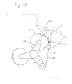
- Fig. 30 illustrates the apparatus for feeding the web of paper 8, 8'.
- the apparatus comprises a shaft 58 including three reel arms 60 and supported on side frames 62 for rotation.
- the reel arms 60 each includes roll 6, 6' mounted at the end thereof for rotation, the web of paper 8' being fed from the roll 6'.
- the apparatus further includes drive means connected to the shaft 58 for swingingly moving the reel arms 60 clockwise about the shaft 58 when the roll 6' decreases in diameter, as shown in Fig. 31, so that the roll 6 approaches the web of paper 8' from the roll 6'.
- the apparatus further includes drive means for rotatingly moving the roll 6 counterclockwise about the central axis thereof.
- a sensor detects if the residual of the web of paper 8' decreases to a small amount on the roll 6', to generate a signal.
- the drive means swingingly moves the reel arms 60 again in response to the signal from the sensor, so that the roll 6 engages with the web of paper 8', as shown in Fig. 32.
- the apparatus further includes drive means for swingingly moving a paster arm 64 clockwise about a pin 66 toward the roll 6, the paster arm 64 including a brush 68 mounted thereon, so that the web of paper 8' is pressed against the outer surface of the roll 6 by the brush 68. The web of paper 8' is therefore adhered to the adhesive double coated tape 40 on the roll 6 to join the two webs of paper 8, 8' together.
- the paster arm 64 further includes a knife 70 which is connected to drive means mounted on the paster arm 64. The knife 70 is pressed against the web of paper 8' by the drive means to cut the web of paper 8', immediately after joining the two webs of paper 8, 8' together, as shown in Fig. 33.
- the drive means then swingingly moves the paster arm 64 back to the position in Fig 30 and swingingly moves the reel arms 60 again to the position in which the web of paper 8 is fed from the roll 6, as shown in Fig. 34.
Abstract
There is disclosed a method of opening a package
including a content wrapped with a wrapper. The method
comprises the step of directing a laser beam to the wrapper for
cutting the wrapper with the laser beam to open the package.
The method further comprises the step of protecting the content
from being damaged by the laser beam. Also disclosed is
apparatus for opening a said package including a laser beam
source, and a package to be opened using said apparatus.
Description
The invention relates to a method of opening a package including
a content wrapped with a wrapper. The content may comprise a roll
including a web of paper wound thereon to form multi-layers, or sheets
of paper stacked into multi-layers. The web or sheets may be adapted to
be printed or converted. In addition, the invention relates to the
structure of the package. The invention further relates to an apparatus
for opening the package.
There has been generally used a roll R including a web of paper
wound thereon to form multi-layers, for example in a web-fed press for
newspaper or magazine, as shown in Fig. 35 and Fig. 36. The roll R is
wrapped with a wrapper W for transportation and storage to form a
package P including the roll R therein. The wrapper W keeps the roll R
from being damaged. Accordingly, first of all, it is required to cut the
wrapper W circumferentially of the package P at the opposite end
portions thereof and then cut the wrapper W axially of the package P, to
open the package P. The roll R is taken out of the package P and
mounted on the web-fed press. The web of paper is fed from the roll R
and printed by the web-fed press.
As to the operation to open the package P, it is conventional to
manually out the wrapper W with a knife and a bamboo spatula. An
operator manipulates the knife at the opposite end portions of the
package P to cut the wrapper W circumferentially of the package P. The
operator then inserts the bamboo spatula between the wrapper W and the
roll R at one of the opposite end portions of the package P and move
the bamboo spatula axially of the package P, to out the wrapper W
axially of the package P.
However, the roll R is very heavy. In addition, the wrapper W
generally comprises a wrapping paper which is durable and strong. The
wrapping paper is closely fitted on the outer surface of the roll R. It
is therefore troublesome to manually and conveniently cut the wrapper W
with the knife and the bamboo spatula. Labour and time are required. It
has also been a problem that the roll R may be damaged by the
bamboo spatula inserted between the wrapper W and the roll R and
moved axially of the package P. It is a task of extreme
difficulty to manually and conveniently cut the wrapper W to
open the package P, without damage to the roll R.
There has been heretofore proposed an apparatus for
automatically cutting the wrapper to open the package, as disclosed in
Japanese Laid-Open Patent Publication No. 311, 438 of 1992. The
apparatus includes a knife having a portion of T-shaped cross section
and equipments for inserting the knife between the wrapper and the roll
and moving the knife axially of the package, to out the wrapper axially
of the package. However, the equipments are complicated and expensive.
It takes much time to open the package. It has also been a
problem that the knife is liable to be worn and damaged by the
durable and strong wrapping paper. It is therefore required to
frequently exchange the knife for new one.
There has been also used sheets of paper stacked into multi-layers,
in the sheet-fed press. The sheets are wrapped with a wrapper
for transportation and storage to form a package including the sheets
therein, like the roll of web. Accordingly, it is required to cut the
wrapper to open the package.
As to the web and sheets to be converted by a paper converting
machine, it is also required to cut the wrapper to open the package.
It is therefore an object of the invention to provide a new and
improved method of opening a package including a content wrapped with a
wrapper, and an apparatus therefore, to thereby overcome the above
problems.
Another object of the invention is to conveniently cut the
wrapper and open the package, without damage of the content.
Other object of the invention is to conveniently cut the wrapper
and open the package, without complicated and expensive equipments.
Other object of the invention is to conveniently cut the wrapper
and open the package, without taking much time.
Other object of the invention is to conveniently cut the wrapper
and open the package, without the problem relating to the wear and
damage of knife.
According to the invention, there is provided a method of
opening a package including a content wrapped with a wrapper. The method
comprises the step of directing a laser beam to the wrapper for cutting
the wrapper with the laser beam to open the package. The method further
comprises the step of protecting the content from being damaged by the
laser beam.
According to a further aspect of the invention, there is
also provided a package to be opened. The package comprises a
covering layer of material having a laser beam absorptivity
which is lower than that of the wrapper. The covering layer may
be interposed between the wrapper and the content for covering
the content from the laser beam to protect the content from
being damaged by the laser beam.
The material may be coated on or impregnated into the inner
surface of the wrapper to form the covering layer.
The material may be coated on or impregnated into the outer
surface of the content to form the covering layer.
In another embodiment, the content is of multi-layers. The
covering layer is interposed between the layers of the content adjacent
to the outer surface of the content for covering the content from the
laser beam to protect the content from being damaged by the laser beam.
In another embodiment, the material may be coated on or
impregnated into at least one layer of the content adjacent to
the outer surface to form the covering layer.
The content may comprise a roll including a web of paper wound
thereon to form multi-layers, or sheets of paper stacked into multi-layers.
The web or sheets may be adapted to be printed or converted.
The wrapper may be made of paper, plastic film or fabric.
The covering layer may be formed of a foil of metal.
The covering layer may extend substantially all over the
circumference of the content.
The covering layer may comprise an elongate strip. The package
may be intended for the wrapper to be cut with the laser beam
along the strip.
In another embodiment, the step of protecting the content
comprises the step of utilizing a type of laser beam not capable of
cutting the web or sheets. The wrapper comprises a wrapping paper having
a laser beam absorptivity which is higher than that of the web or
sheets with respect to the type of laser beam to cut the wrapping paper
and open the package with the laser beam.
In a further embodiment, the wrapping paper may include a
material admixed thereinto and having a high absorptivity with
respect to the type of laser beam.
The method may further comprise the step of moving the package
relative to the laser beam.
In a preferred embodiment, the package is cylindrical. The step
of moving the package comprises the step of rotatingly moving the
package about the central axis thereof for cutting the wrapper
circumferentially of the package at the opposite end portions of the
package. The step of moving the package further comprises the step of
linearly moving the package axially thereof for cutting the wrapper in
the axial direction of the package.
The step of moving the package may comprise the step of linearly
moving the package axially thereof while rotatingly moving the package
about the central axis thereof for cutting the wrapper spirally.
In another embodiment, the method further comprises the step of
sweeping the laser beam over the package which is held in position.
The step of sweeping the laser beam may comprise the step of
linearly sweeping the laser beam axially of the package for cutting the
wrapper in the axial direction of the package.
According to a further aspect of the invention there is
also provided an apparatus for opening a package. The
apparatus comprises support means for supporting the package thereon at
a fixed position. The apparatus further comprises a laser beam source
for directing a laser beam to the wrapper and linearly sweeping the
laser beam over the wrapper to cut the wrapper with the laser beam in
the axial direction of the package.
In another embodiment, the apparatus further comprises
guide means adapted to guide the support means for linear
movement axially of the package to cut the wrapper with the
laser beam in the axial direction of the package.
In case of the package which is cylindrical, the support means
may include guide means for guiding the package for rotational movement
about the central axis thereof on the support means while directing the
laser beam to the wrapper, to cut the wrapper circumferentially of the
package at the opposite end portions of the package.
The support means may include first drive means for rotatingly
moving the package about the central axis thereof on the support means
while directing the laser beam to the wrapper, to cut the wrapper
circumferentially of the package at the opposite end portions of the
package. The apparatus may further comprise second drive means for
linearly moving the support means axially of the package to cut the
wrapper with the laser beam in the axial direction of the package.
In connection to the covering layer interposed between the
content and the wrapper or between the layers of the content adjacent
to the outer surface of the content, the apparatus may further comprise
detector means for detecting the covering layer, and control means for
controlling the first and second drive means in response to a signal
from the detector means to direct the laser beam to the package at the
position of the covering layer.
In another embodiment, the roll includes a web of paper wound
thereon and an adhesive double coated tape which includes two adhesive
layers formed on the opposite sides thereof and a release agent double
coated paper adhered to one of the adhesive layers, the other adhesive
layer being adhered to the end of the web. The adhesive double coated
tape further includes a covering layer of material having a laser beam
absorptivity which is lower than that of the wrapper for covering the
roll from the laser beam to protect the roll from being damaged by the
laser beam.
The adhesive double coated tape may be adhered to the end of the
web all over the width thereof.
There is also provided an adhesive double coated tape comprising
an elongate substrate. Two adhesive layers are formed on the opposite
sides of the substrate. A release agent double coated paper is adhered
to one of the adhesive layers. A covering layer is formed on one of the
opposite sides of the release agent double coated paper, the covering
layer being of material having a low absorptivity with respect to a
type of laser beam.
The covering layer may be formed on one of the opposite sides of
the substrate.
The type of laser beam may comprise CO2 laser beam. The covering
layer may comprise 2 foil of metal such as aluminum.
The covering layer may be adhered to one of the opposite sides
of the release agent double coated paper or the substrate.
The covering layer may be coated on one of the opposite sides of
the release agent double coated paper or the substrate.
The covering layer may be vapour deposited on one of the
opposite sides of the release agent double coated paper or the
substrate.
The adhesive double coated tape may comprise an elongate
substrate of material having a low absorptivity with respect to a type
of laser beam.
The substrate may be made of metal such as aluminum.
In a preferred embodiment, the elongate substrate includes a
portion weakened to be torn along a straight tearing line extending
longitudinally of the substrate adjacent to one edge thereof. The
substrate is free from one of the adhesive layers at least between the
tearing line and the one edge of the substrate. An elongate void is
formed in and clear of the other adhesive layer along the tearing line.
Fig. 1 is a perspective view of a package including a content
wrapped with a wrapper according to the invention, the content
comprising a roll including a core about which a web of paper is wound
to form multi-layers.
Fig. 2 is a perspective view of the package of Fig. 1 in which
an end paper is removed and the wrapper is partially broken to show the
web and the core.
Fig. 3 is a perspective view of a package in which the wrapper
is partially broken to show a covering layer interposed between the
wrapper and the roll in a preferred embodiment of the invention.
Fig. 4 is a side view of the package of Fig. 3.
Fig. 5 is a cross sectional view of the package of Fig. 3.
Fig. 6 is a cross sectional view of a package including a
covering layer interposed between the layers of web adjacent to the
outer surface of the roll in another embodiment.
Fig. 7 is an elevational view of an apparatus for opening the
package in a preferred embodiment of the invention.
Fig. 8 is a side view of the apparatus of Fig. 7.
Fig. 9 to Fig. 12 are explanatory views showing the steps of
opening the package in the apparatus of Fig. 7, respectively.
Fig. 13 is a perspective view of a package including a content
wrapped with a wrapper according to the invention, the content
comprising sheets of paper stacked into multi-layers.
Fig. 14 is a plan and sectional view of the package of Fig. 13.
Fig. 15 is a side and sectional view of the package of Fig. 13.
Fig. 16 is an explanatory view showing the step of opening the
package in a preferred embodiment of the invention.
Fig. 17 is an explanatory view showing the step of opening the
package in another embodiment.
Fig. 18 is a perspective view showing a roll including a web of
paper wound thereon and an adhesive double coated tape adhered to the
end of the web in a preferred embodiment of the invention.
Fig. 19 is a cross sectional view of the roll and the adhesive
double coated tape of Fig. 18.
Fig. 20 is a plan view of the adhesive double coated tape of
Fig. 19, a release agent double coated paper being removed.
Fig. 21 is a bottom view of the adhesive double coated tape of
Fig. 19.
Fig. 22 is a bottom view of a adhesive double coated tape in
another embodiment.
Fig. 23 is a cross sectional view of an adhesive double coated
tape in other embodiment.
Fig. 24 is a cross sectional view of an adhesive double coated
tape in other embodiment.
Fig. 25 is 2 cross sectional view of an adhesive double coated
tape in other embodiment.
Fig. 26 is a cross sectional view of an adhesive double coated
tape in other embodiment.
Fig. 27 is an explanatory view showing the step of opening a
package including the roll and the adhesive double coated tape.
Fig. 28 is an explanatory view showing the release agent double
coated paper removed from the adhesive layer of the adhesive double
coated tape of Fig. 27.
Fig. 29 is an explanatory view showing another web of paper
adhered to the adhesive layer of the adhesive double coated tape of Fig.
28.
Fig. 30 to Fig. 34 are explanatory views showing the steps of
joining two webs of paper together, respectively.
Fig. 35 is a perspective view of a package in prior art.
Fig. 36 is a perspective view of the package of Fig. 35 in which
an end paper is removed and a wrapper is partially broken to show a
roll wrapped with a wrapper.
Turning now to the drawings, Fig. 1 illustrates a package 2
including a content wrapped with a wrapper 4, according to the
invention. The package 2 is cylindrical. The content comprises a roll 6
including a web of paper 8 wound thereon to form multi-layers, as shown
in Fig. 2. In the embodiment, the roll 6 includes a core 10 about which
the web of paper 8 is wound. The web of paper 8 is adapted to be
printed or converted. The wrapper 4 comprises a wrapping paper which is
durable and strong. The wrapping paper is closely fitted on the outer
surface of the roll 6 and folded along the opposite end surfaces of the
roll 6. Two end papers 12 are adhered to the folded portions of the
wrapping paper to cover the opposite end surfaces of the roll 6. The
wrapper 4 may be made of plastic film or fabric.
The package is intended such that a laser beam can be
directed to the wrapper 4 for cutting the wrapper 4 with the
laser beam. In addition, the package 2 is arranged to protect
the roll 6 from being damaged by the laser beam.
In this connection, in a preferred embodiment of the invention
shown in Fig. 3 to Fig. 5, the package 2 includes a intercepting or
covering layer 14 of material having a laser beam absorptivity which is
lower than that of the wrapper 4. The covering layer 14 is interposed
between the wrapper 4 and the roll 6 for intercepting the laser beam
between the wrapper 4 and the roll 6. The covering layer 14 therefore
covers the roll 6 from the laser beam to protect the roll 6 from being
damaged by the laser beam.
The laser beam may comprise CO2 laser beam which can cut the
wrapper 4 made of paper, plastic film or fabric. The covering layer 14
may be formed of a foil of metal such as aluminum. The foil may be
adhered or bonded to the inner surface of the wrapper 4 to form the
covering layer 14. The foil may be adhered or bonded to the outer
surface of the roll 6 to form the covering layer 14. Metal has a laser
beam absorptivity which is lower than that of the wrapper 4 with respect
to CO2 laser beam. Accordingly, the covering layer 14 can cover the
roll 6 from the laser beam to protect the roll 6 from being damaged by
the laser beam.
An experiment has been made on the roll 6 wrapped with
duplicated wrapping papers each having a thickness of 0.1 mm, and the
foil of aluminum having a thickness of 0.05 mm and interposed between
the duplicated wrapping papers and the roll 6. The experiment has swept
a laser beam over the duplicated wrapping papers at a speed of 3 m/sec.
It has merely cut the duplicated wrapping papers. The roll 6 has been
not damaged at all.
The covering layer 14 may be formed of a material including a
powdered metal admixed thereinto. The material may be coated on or
impregnated into the inner surface of the wrapper 4 to form the
covering layer 14. The material may be coated on or impregnated into
the outer surface of the roll 6 to form the covering layer 14. The
material may be impregnated into a fabric adhered or bonded to the
inner surface of the wrapper 4 or the outer surface of the roll 6 to
form the covering layer 14.
The covering layer 14 may be interposed between the layers of
the web adjacent to the outer surface of the roll 6, as shown in Fig. 6,
for covering the roll 6 from the laser beam to protect the roll 6 from
being damaged by the laser beam. In the embodiment, the material may be
coated on or impregnated into at least one layer of the roll 6 adjacent
to the outer surface of the roll 6 to form the covering layer 14.
In addition, the covering layer 14 may comprise an elongate
strip which includes a straight portion extending axially of the
package 2, as shown in Fig. 3 and 4. The strip further includes two
annular portions extending circumferentially of the package 2 at the
opposite end portions of the package 2. The package 2 is intended so that
the wrapper 4 can be cut with the laser beam along the strip.
Fig. 7 and Fig. 8 illustrate an apparatus for opening the
package 2, acccording to the invention. The apparatus includes support
means comprising a carriage 16 for supporting the package 2 thereon. The
apparatus further includes a laser beam source 18 mounted on a frame 20
for directing a laser beam to the wrapper 4. In addition, the apparatus
includes guide means comprising a guide bed 22 for guiding the carriage
16 for linear movement axially of the package 2. In the embodiment,
the carriage 16 includes wheels 24 which are fitted in and rolled along
grooves formed in the guide bed 22 to guide the carriage 16 for
linear movement axially of the package 2. The carriage 16 further
includes guide means comprising rollers 26 between which the package 2
is supported for guiding the package 2 for rotational movement about
the central axis thereof on the carriage 16.
In the apparatus, an operator can linearly move the carriage 16
along with the package 2 axially of the package 2 to position one of the
opposite end portions of the package 2 below the laser beam source 18,
as shown in Fig. 9 and Fig. 10. The operator then rotatingly moves the
package 2 about the central axis thereof and operates the laser beam
source 18 for directing the laser beam to the wrapper 4, to cut the
wrapper 4 circumferentially of the package 2 at one of the end portions
of the package 2. The covering layer 14 includes two annular portions
extending circumferentially of the package 2 at the opposite end
portions of the package 2, as described previously, so that the
operator can cut the wrapper 4 with the laser beam along the annular
portion of the covering layer 14. The covering layer 14 therefore covers
the roll 6 from the laser beam to protect the roll 6 from being damaged
by the laser beam.
The operator then linearly moves the carriage 16 along with the
package 2 axially of the package 2 while directing the laser beam to the
wrapper 4, as shown in Fig. 11, to cut the wrapper 4 with the laser
beam in the axial direction of the package 2. The covering layer 14
includes a straight portion extending axially of the package 2, as
described previously, so that the operator can position the straight
portion of the covering layer 14 below the laser beam source 18 to cut
the wrapper 4 with the laser beam along the straight portion of the
covering layer 14. The covering layer 14 therefore covers the roll 6
from the laser beam to protect the roll 6 from being damaged by the
laser beam. The operator then positions the other end portion of the
package 2 below the laser beam source 18, as shown in Fig. 12, and
rotatingly moves the package 2 about the central axis thereof while
directing the laser beam to the wrapper 4, to cut the wrapper 4
circumferentially of the package 2 at the other end portion of the
package 2. The operator cuts the wrapper with the laser beam along the
annular portion of the covering layer 14 so that the covering layer 14
covers the roll 6 from the laser beam to protect the roll 6 from being
damaged by the laser beam.
Accordingly, two annular cut lines are formed at the opposite
end portions of the package 2 by the laser beam. In addition, a straight
cut line is formed between the annular cut lines by the laser beam. The
wrapper 4 can therefore be partially removed from the opposite end
portions of the package 2 along the annular cut lines. The operator then
engages a tool with the edge of the wrapper 4 formed by the straight
cut line and rotatingly moves the package 2 about the central axis
thereof, to peel the wrapper 4 off the roll 6.
The apparatus therefore can conveniently cut the wrapper 4 and
open the package 2, without damage of the roll 6. It does not involve
complicated and expensive equipments. In addition, it does not
take much time to open the package 2. It has also not a problem
relating to the wear of knife.
The roll 6 is then taken out of the package 2 and mounted on a
web-fed press for newspaper or magazine. The web of paper 8 is fed from
the roll 6 and printed by the web-fed press. The web of paper 8 may be
converted by a paper converting machine.
The apparatus can be arranged to automatically cut the wrapper 4
and open the package 2. In the embodiment, the carriage 16 further
includes first drive means not shown, but mounted on the carriage 16 and
connected to the rollers 26. The apparatus further includes second
drive means not shown, but mounted on the carriage 16 and connected to
the wheels 24. In addition, the apparatus includes detector means 28
comprising a metal sensor for detecting the covering layer 14, and
control means 30 connected to the laser beam source 18, the first and
second drive means and the detector means 28.
The control means 30 controls the first and second drive means
in response to a signal from the detector means 28 in such a way that
the wheels 24 are firstly rotatingly driven by the second drive means
to linearly move the carriage 16 axially of the package 2 to position
one of the opposite end portions of the package 2 below the laser beam
source 18. The rollers 26 are then rotatingly driven by the first drive
means to rotatingly move the package 2 about the central axis thereof.
The laser beam source 18 directs the laser beam to the wrapper 4 to cut
the wrapper 4 circumferentially of the package 2 at one of the end
portions of the package 2. The rollers 26 cooperate with the first drive
means, the detector means 28 and the control means 30 to position the
straight portion of the covering layer 14 below the laser beam source
18. The wheels 24 are then rotatingly driven by the second drive means
to linearly move the carriage 16 axially of the package 2 while
directing the laser beam to the wrapper 4, to cut the wrapper 4 with the
laser beam in the axial direction of the package 2. Finally, the
rollers 26 are rotatingly driven again by the second drive means to cut
the wrapper 4 circumferentially of the package 2 at the other end
portion of the package 2. This can automatically cut the wrapper 4 and
open the package 2.
In the apparatus in Fig. 7 and Fig. 8, the wheels 24 and the
rollers 26 may be rotatingly moved, to linearly move the package 2
axially thereof while rotatingly moving the package 2 about the central
axis thereof for cutting the wrapper 4 spirally. In this connection, the
covering layer 14 may include a spiral portion extending axially of and
about the package 2 to cut the wrapper 4 with the laser beam along the
spiral portion of the covering layer 14. The covering layer 14 may
extend substantially all over the circumference of the roll 6.
The apparatus may be arranged to sweep the laser beam over the
package 2 which is held in position, to thereby open the package 2. For
example, the apparatus may be arranged to rotatingly move the package 2
about the central axis thereof relative to the laser beam for cutting
the wrapper 4 circumferentially of the package 2 at the opposite and
portions of the package 2, and then linearly sweep the laser beam
axially of the package for cutting the wrapper 4 in the axial direction
of the package 2.
In the embodiment shown in Fig. 13 to Fig. 15, a package 32
includes a content wrapped with a wrapper 34, the content comprising
sheets of paper 36 stacked into multi-layers. The sheets of paper 36
are adapted to be printed or converted. The package 32 further includes
a covering layer 38 of material having a laser beam absorptivity which
is lower than that of the wrapper 34, like the covering layer 14 and
the wrapper 4 in Fig. 3. The covering layer 38 is interposed between the
wrapper 34 and the sheets of paper 36 to extend substantially all over
the circumference of the sheets of paper 36. The covering layer 38 may
be adhered or bonded to the inner surface of the wrapper 34 or outer
surface of the sheets of paper 36. The material may be coated or
impregnated into the inner surface of the wrapper 34 or the outer
surface of the sheets of paper 36, to form the covering layer 38.
The package 32 is intended to linearly move the package 32
longitudinally thereof and direct the laser beam to the wrapper 34 from
the laser beam source 18, as shown in Fig. 16, to cut the wrapper 34
and open the package 32. The covering layer 38 covers the sheets of
paper 36 from the laser beam to protect the sheets of paper 36 from
being damaged by the laser beam.
The laser beam source 18 may include a reflector for reflecting
the laser beam toward the wrapper 34. The laser beam source 18 may
further include means for rotatingly moving the reflector to sweep the
laser beam over the package 32 which is held in position, as shown in
Fig. 17. This embodiment can cut the wrapper 34 and open the package 32,
without moving the package 32.
As to the package 2 in Fig. 1, it may be arranged to cut the
wrapper 4 and open the package 2 with a type of laser beam such as YGA
laser beam which is not capable of cutting the web of paper 8. In a
preferred embodiment, the wrapper 4 comprises a wrapping paper which
includes carbon admixed thereinto. Carbon may be admixed into the
wrapping paper in a paper making step. Carbon has a high absorptivity
with respect to the type of the laser beam such as YGA laser beam.
Accordingly, the wrapping paper has a laser beam absorptivity which is
higher than that of the web of paper 4 with respect to the type of the
laser beam. It therefore can cut the wrapper 4 and open the package 2
with the type of laser beam. It also can protect the web of paper 8 from
being cut or damaged by the laser beam. The wrapping paper may include
a material other than carbon, admixed thereinto and having a high
absorptivity with respect to the type of laser beam.
As to the package 32 in Fig. 13, the wrapper 34 may also
comprise a wrapping paper which includes a material such as carbon
admixed thereinto and having a high absorptivity with respect to the
type of laser beam such as YGA laser beam, so that the wrapping paper
has a laser beam absorptivity which is higher than that of the sheets
of paper 36 with respect to the type of the laser beam. This can cut
the wrapper 34 and open the package 32 with the type of laser beam, and
protect the sheets of paper 36 being damaged by the laser beam, even if
no covering layer 38 is interposed between the wrapper 34 and the sheets
of paper 36.
In the embodiment shown in Fig. 18, the package 2 includes a
content wrapped with a wrapper 4, the content comprising the roll 6
including the web of paper 8 wound thereon and an adhesive double
coated tape 40 which includes two adhesive layers 42 formed on the
opposite sides thereof, as shown in Fig. 19. A release agent double
coated paper 44 is adhered to one of the adhesive layers 42. The
adhesive double coated tape 40 is drawn and supplied from a roll 46 of
tape to extend axially of the roll 6, the other adhesive layer 42 being
adhered to the end of the web 8. In the embodiment, the adhesive double
coated tape 40 is adhered to the end of web 8 all over the width thereof
between the opposite end surfaces of the roll 6, and cut into a length
at the position of the end surface of the roll 6. The roll 6 and the
adhesive double coated tape 40 thereon are then wrapped with the
wrapper 4.
The adhesive double coated tape 40 further includes a covering
layer 48 of material having a laser beam absorptivity which is lower
than that of the wrapper 4 for covering the roll 6 from the laser beam
to protect the roll 6 from being damaged by the laser beam. The
covering layer 48 is formed on one of the opposite sides of the release
agent double coated paper 44. The covering layer 48 is of material
having a low absorptivity with respect to a type of laser beam.
In the embodiment, the adhesive double coated tape 40 has a
width of about 10 cm, and extends between the end of the web 8 and the
outer surface of the roll 6. The adhesive double coated tape 40 is
adhered to the end of the web 8 and the outer surface of the roll 6 to
join the end of the web 8 and the outer surface of the roll 6. In
addition, the adhesive double coated tape 40 includes an elongate
substrate 50 made of paper, fabric or plastic film, the adhesive layers
42 being formed on the opposite sides of the substrate 50. The substrate
50 includes a portion weakened by perforations 52 to be torn along a
straight tearing line extending longitudinally of the substrate 50
adjacent to one edge 54 thereof, as shown in Fig. 21. The substrate 50
is free from one of the adhesive layers 42 on the outer side of the
substrate 50 at least between the tearing line having the perforations
52 and the one edge 54 of the substrate 50, as shown in Fig. 20. The
covering layer 48 is formed on the inner side of the release agent
double coated paper 44 to have a width of about 3 cm, in stead of the
adhesive layer 42. In addition, an elongate void 56 is formed in and
clear of the other or inner adhesive layer 42 along the tearing line,
at a distance of about 1.5 cm from the one edge 54 of the substrate 50.
The void 56 has a width of about 1.5 cm. The other adhesive layer 42 is
adhered to the end of the web 8 and the outer surface of the roll 6 to
position the void 56 between the end of the web 8 and the outer surface
of the roll 6.
The adhesive layers 42 may include portions formed between the
one edge 54 of the substrate 50 and the void 56 and spaced from each
other at a distance in the longitudinal direction of the adhesive double
coated tape 40, as shown in Fig 22.
The covering layer 48 may be formed all through the inner side
of the release agent double coated paper 44, as shown in Fig. 23. In
the embodiment, the covering layer 48 includes a release agent coated on
the inner side thereof which is adhered to the outer adhesive layer 42
of the substrate 50.
The covering layer 48 may be formed on the outer side of the
release agent double coated paper 44, as shown in Fig. 24, to have a
width of about 3 cm, in the portion free from one one of the adhesive layers
42 on the outer side of the substrate 50. The covering layer 48
includes a release agent coated on the outer surface thereof.
The covering layer 48 may be formed on the outer side of the
substrate 50, as shown in Fig. 25. The outer adhesive layer 42 is
formed on the covering layer 48, the release agent double coated paper
44 being adhered to the outer adhesive layer 42.
The package 2 may be intended for the direction of a type
of laser beam comprising CO2 laser beam, to the wrapper 4. In
this case, the covering layer 48 may comprise a foil or metal
such as aluminium.
The covering layer 48 may be adhered to one of the opposite
sides of the release agent double coated paper 44 or the substrate 50.
The covering layer 48 may be coated on one of the opposite sides of the
release agent double coated paper 44 or the substrate 50. The covering
layer 48 may be vapour deposited on one of the opposite sides of the
release agent double coated paper 44 or the substrate 50.
The adhesive double coated tape 40 may include an elongate
substrate 50 of material having a low absorptivity with respect to a
type of laser beam, as shown in Fig. 26, for covering the roll 6 from
the laser beam to protect the roll 6 from being damaged by the laser
beam, without the covering layer 48. The package 2 may be intended for
the direction of a type of laser beam comprising CO2 laser beam,
to the wrapper 4. The substrate 50 may be made of metal such as
aluminium.
The laser beam source 18 is arranged to direct the laser beam to
the wrapper 4 along the adhesive double coated tape 40, as shown in
Fig. 27, to cut the wrapper 4 and open the package 2. The covering
layer 48 covers the roll 6 from the laser beam. In the embodiment shown
in Fig. 26, the substrate 50 covers the roll 6 from the laser beam.
The roll 6 can therefore be taken from the package 2. An
operator then peels the release agent double coated paper 44 off the
adhesive layer 42 of the substrate 50, as shown in Fig. 28.
The web of paper 8 is intended to be printed in a web-fed press.
The web of paper 8 may be intended to be converted in a converting
machine. The web-fed press or converting machine includes an apparatus
for feeding the web of paper 8, the roll 6 being mounted on the
apparatus. In the apparatus, another web of paper 8' is adhered to the
adhesive layer 42 of the adhesive double coated tape 40 to join the two
webs of paper 8, 8' together, as shown in Fig. 29. The substrate 50 is
then torn along the tearing line having the perforations 52 by a
tension in the webs of paper 8, 8' when the webs of paper 8, 8' are fed.
Fig. 30 illustrates the apparatus for feeding the web of paper
8, 8'. The apparatus comprises a shaft 58 including three reel arms 60
and supported on side frames 62 for rotation. The reel arms 60 each
includes roll 6, 6' mounted at the end thereof for rotation, the web of
paper 8' being fed from the roll 6'.
The apparatus further includes drive means connected to the
shaft 58 for swingingly moving the reel arms 60 clockwise about the
shaft 58 when the roll 6' decreases in diameter, as shown in Fig. 31, so
that the roll 6 approaches the web of paper 8' from the roll 6'. The
apparatus further includes drive means for rotatingly moving the roll 6
counterclockwise about the central axis thereof. A sensor detects if the
residual of the web of paper 8' decreases to a small amount on the roll
6', to generate a signal. The drive means swingingly moves the reel
arms 60 again in response to the signal from the sensor, so that the
roll 6 engages with the web of paper 8', as shown in Fig. 32.
The apparatus further includes drive means for swingingly moving
a paster arm 64 clockwise about a pin 66 toward the roll 6, the paster
arm 64 including a brush 68 mounted thereon, so that the web of paper 8'
is pressed against the outer surface of the roll 6 by the brush 68. The
web of paper 8' is therefore adhered to the adhesive double coated tape
40 on the roll 6 to join the two webs of paper 8, 8' together. The
paster arm 64 further includes a knife 70 which is connected to drive
means mounted on the paster arm 64. The knife 70 is pressed against the
web of paper 8' by the drive means to cut the web of paper 8',
immediately after joining the two webs of paper 8, 8' together, as
shown in Fig. 33.
The drive means then swingingly moves the paster arm 64 back to
the position in Fig 30 and swingingly moves the reel arms 60 again to
the position in which the web of paper 8 is fed from the roll 6, as
shown in Fig. 34.
Claims (33)
- A method of opening a package including a content wrapped with a wrapper, said method comprising the steps of:directing a laser beam to said wrapper for cutting said wrapper with said laser beam to open said package; andprotecting said content from being damaged by said laser beam.
- The method of claim 1 wherein said content comprises a roll including a web of paper wound thereon to form multi-layers or sheets of paper stacked into multi-layers, said web or sheets being adapted to be printed or converted, and wherein said step of protecting the content comprises the step of utilizing a type of laser beam not capable of cutting said web or sheets, said wrapper comprising a wrapping paper having a laser beam absorptivity which is higher than that of said web or sheets with respect to said type of laser beam to cut said wrapping paper and open said package with said laser beam.
- The method of claim 2, wherein said wrapping paper includes a material admixed thereinto and having a high absorptivity with respect to said type of laser beam.
- The method of any preceding claim, further comprising the step of moving said package relative to said laser beam.
- The method of claim 4, wherein said package is cylindrical, and wherein said step of moving said package comprises the step of rotatingly moving said package about the central axis thereof for cutting said wrapper circumferentially of said package at the opposite end portions of said package, and the step of linearly moving said package axially thereof for cutting said wrapper in the axial direction of said package.
- The method of claim 4, wherein said package is cylindrical, and wherein said step of moving said package comprises the step of rotatingly moving said package about the central axis thereof for cutting said wrapper circumferentially of said package at the opposite end portions of said package, and the step of linearly moving said package axially thereof while rotatingly moving said package about the central axis thereof for cutting said wrapper spirally.
- The method of any of claims 1 to 3, further comprising the step of sweeping said laser beam over said package which is held in position.
- The method of claim 7, wherein said package is cylindrical, and further comprising rotatingly moving said package about the central axis thereof relative to said laser beam for cutting said wrapper circumferentially of said package at the opposite end portions of said package, said step of sweeping said laser beam comprising the step of linearly sweeping said laser beam axially of said package for cutting said wrapper in the axial direction of said package.
- An apparatus for opening a package by utilizing the method of any of claims 1 to 8, said apparatus comprising:support means for supporting said package thereon at a fixed position; anda laser beam source for directing a laser beam to said wrapper and linearly sweeping the laser beam over said wrapper to cut said wrapper with said laser beam in the axial direction of said package.
- An apparatus for opening a package by utilizing the method of any of claims 1 to 8, said apparatus comprising:support means for supporting said package thereon;a laser beam source for directing a laser beam to said wrapper; andguide means adapted to guide said support means for linear movement axially of said package to cut said wrapper with said laser beam in the axial direction of said package.
- The apparatus of claim 9 or 10 wherein said package is cylindrical, and wherein said support means includes guide means for guiding said package for rotational movement about the central axis thereof on said support means while directing said laser beam to said wrapper, to cut said wrapper circumferentially of said package at the opposite end portions of said package.
- An apparatus for opening a cylindrical package by utilizing the method of any one of claims 1 to 8, said apparatus comprising:support means for supporting said package thereon;a laser beam source for directing a laser beam to said wrapper, said support means including first drive means for rotatingly moving said package about the central axis thereof on said support means while directing said laser beam to said wrapper, to cut said wrapper circumferentially of said package at the opposite end portions of said package; andsecond drive means for linearly moving said support means axially of said package to cut said wrapper with said laser beam in the axial direction of said package.
- The apparatus of claim 12, wherein said content is of multi-layers, and wherein said package comprises a covering layer of material having a laser beam absorptivity which is lower than that of said wrapper, said covering layer being interposed between said content and said wrapper or between the layers of said content adjacent to the outer surface of said content to cover said content from said laser beam so that said content may not be damaged by said laser beam said apparatus further comprising detector means for detecting said covering layer, and control means for controlling said first and second drive means in response to a signal from said detector means to direct said laser beam to said package at the position of said covering layer.
- A package to be opened by utilizing the method of claim 1, said package comprising a covering layer of material having a laser beam absorptivity which is lower than that of said wrapper, said covering layer being interposed between said wrapper and said content for covering said content from said laser beam to protect said content from being damaged by said laser beam.
- The package of claim 14, wherein said material is coated on or impregnated into the inner surface of said wrapper to form said covering layer.
- The package of claim 14, wherein said material is coated on or impregnated into the outer surface of said content to form said covering layer.
- A package to be opened by utilizing the method of claim 1, said package comprising a covering layer of material having a laser beam absorptivity which is lower than that of said wrapper, said content being of multi-layers, said covering layer being interposed between the layers of said content adjacent to the outer surface of said content for covering said content from said laser beam to protect said content from being damaged by said laser beam.
- The package of claim 17, wherein said material is coated on or impregnated into at least one layer of said content adjacent to said outer surface to form said covering layer.
- The package of any one of claims 14 to 18, wherein said content comprises a roll including a web of paper wound thereon to form multi-layers, or sheets of paper stacked into multi-layers, said web or sheets being adapted to be printed or converted, and wherein said wrapper is made of paper, plastic film or fabric.
- The package of any one of claims 14 to 18, wherein said covering layer is formed of a foil of metal.
- The package of any one of claims 14 to 18, wherein said covering layer extends substantially all over the circumference of said content.
- The package of any one of claims 14 to 18, wherein said covering layer comprises an elongate strip, said package being intended to cut said wrapper with said laser beam along said strip.
- A package to be opened by utilizing the method of claim 1, said content comprising a roll including a web of paper wound thereon and an adhesive double coated tape which includes two adhesive layers formed on the opposite sides thereof and a release agent double coated paper adhered to one of the adhesive layers, the other adhesive layer being adhered to the end of said web, said adhesive double coated tape further including a covering layer of material having a laser beam absorptivity which is lower than that of said wrapper for covering said roll from said laser beam to protect said roll from being damaged by said laser beam.
- The package of claim 23 wherein said adhesive double coated tape is adhered to said end of the web all over the width thereof.
- An adhesive double coated tape comprising:an elongate substrate;two adhesive layers formed on the opposite sides of said substrates;a release agent double coated paper adhered to one of said adhesive layers; anda covering layer formed on one of the opposite sides of said release agent double coated paper, said covering layer being of material having a low absorptivity with respect to a type of laser beam.
- An adhesive double coated tape comprising:an elongate substrate;two adhesive layers formed on the opposite sides of said substrate;a release agent double coated paper adhered to one of said adhesive layers; anda covering layer formed on one of the opposite sides of said substrate, said covering layer being of material having a low absorptivity with respect to a type of laser beam.
- The adhesive double coated tape of claim 25 or 26 wherein said type of laser beam comprises CO2 laser beam, and wherein said covering layer comprises a foil of metal such as aluminum.
- The adhesive double coated tape of claim 25 or 26 wherein said covering layer is adhered to one of the opposite sides of said release agent double coated paper or said substrate.
- The adhesive double coated tape of claim 25 or 26 wherein said covering layer is coated on one of the opposite sides of said release agent double coated paper or said substrate.
- The adhesive double coated tape of claim 25 or 26 wherein said covering layer is vapour deposited on one of the opposite sides of said release agent double coated paper or said substrate.
- An adhesive double coated tape comprising:an elongated substrate of material having a low absorptivity with respect to a type of laser beam;two adhesive layers formed on the opposite sides of said substrate; anda release agent double coated paper adhered to one of said adhesive layers.
- The adhesive double coated tape of claim 31 wherein said type of laser beam comprises CO2 laser beam, and wherein said substrate is made of metal such as aluminum.
- An adhesive double coated tape comprising:an elongate substrate including a portion weakened to be torn along a straight tearing line extending longitudinally of the substrate adjacent to one edge thereof;two adhesive layers formed on the Opposite sides of the substrate, said substrate being free from one of the adhesive layers at least between said tearing line and said one edge of the substrate;an elongated void formed in and clear of the other adhesive layer along said tearing line; anda release agent double coated paper adhered to said one of the adhesive layers.
Applications Claiming Priority (6)
| Application Number | Priority Date | Filing Date | Title |
|---|---|---|---|
| JP70368/97 | 1997-03-07 | ||
| JP7036897 | 1997-03-07 | ||
| JP9208507A JPH1135017A (en) | 1997-07-16 | 1997-07-16 | Method and device for unsealing packaged article |
| JP208507/97 | 1997-07-16 | ||
| JP30919597A JPH11124110A (en) | 1997-10-22 | 1997-10-22 | Continuous paper splice tape and continuous paper |
| JP309195/97 | 1997-10-22 |
Publications (1)
| Publication Number | Publication Date |
|---|---|
| EP0864501A2 true EP0864501A2 (en) | 1998-09-16 |
Family
ID=27300309
Family Applications (1)
| Application Number | Title | Priority Date | Filing Date |
|---|---|---|---|
| EP98301567A Withdrawn EP0864501A2 (en) | 1997-03-07 | 1998-03-03 | Method and apparatus for opening a package |
Country Status (4)
| Country | Link |
|---|---|
| US (1) | US6395361B1 (en) |
| EP (1) | EP0864501A2 (en) |
| KR (1) | KR19980079967A (en) |
| CN (1) | CN1195632A (en) |
Cited By (7)
| Publication number | Priority date | Publication date | Assignee | Title |
|---|---|---|---|---|
| EP1175829A2 (en) * | 2000-07-27 | 2002-01-30 | Lely Welger Maschinenfabrik GmbH | Unwrapping device for the covering of agricultural produce bales |
| EP1329388A1 (en) * | 2002-01-22 | 2003-07-23 | British American Tobacco (Germany) GmbH | Method and apparatus for removing an overwrapping from cigarette packages |
| DE102004043089A1 (en) * | 2004-09-07 | 2006-03-09 | Man Roland Druckmaschinen Ag | Printing paper roll`s outline package separating method , involves moving paper roll to stationary separating device, and separating outline package by separating device using relative movement between roll and separating device |
| DE102004043102A1 (en) * | 2004-09-07 | 2006-03-09 | Man Roland Druckmaschinen Ag | System and method for unpacking a printing paper roll |
| DE102006019745A1 (en) * | 2006-04-28 | 2007-10-31 | Elektro-Maschinen Und Apparatebau Rink Gmbh | Device for removal of foil shrunk on container, has transport device for container and trimming device slashed off shrunk on foil on container and lifting device removes shrunk on foil from container |
| WO2018001553A1 (en) * | 2016-06-27 | 2018-01-04 | Giesecke+Devrient Currency Technology Gmbh | Device and method for separating a banderole |
| US11904490B2 (en) | 2018-08-10 | 2024-02-20 | Walmart Apollo, Llc | Systems and methods for high throughput cutting of sealing elements on packages |
Families Citing this family (5)
| Publication number | Priority date | Publication date | Assignee | Title |
|---|---|---|---|---|
| CN102079407B (en) * | 2009-11-27 | 2014-02-19 | 深圳市大族激光科技股份有限公司 | Method for opening box by cutting packing tape with laser |
| EP3049243B1 (en) * | 2013-08-26 | 2018-07-25 | Federal-Mogul Powertrain LLC | Protective textile sleeve with hot melt fixation, end fray prevention layer and methods of construction and application thereof |
| DE102014220279B4 (en) * | 2014-10-07 | 2017-10-05 | Louis Seriot | Method, device and their use for deflating packaged objects |
| KR102157893B1 (en) * | 2016-07-25 | 2020-09-18 | 주식회사 엘지화학 | Apparatus for removing battery tube |
| CN110053839A (en) * | 2019-04-24 | 2019-07-26 | 广州广林科技有限公司 | A kind of intelligence unpacking equipment |
Family Cites Families (9)
| Publication number | Priority date | Publication date | Assignee | Title |
|---|---|---|---|---|
| US4125739A (en) * | 1976-12-02 | 1978-11-14 | The Dow Chemical Company | Cable shielding tape and cable |
| US4695493A (en) * | 1986-12-15 | 1987-09-22 | Century Adhesives Corp. | Peel-and-stick carpet assemblies, components thereof and methods of construction |
| JPS63307030A (en) | 1987-06-09 | 1988-12-14 | Tsubakimoto Chain Co | Apparatus for opening sheathing paper of roll paper |
| JPH04311438A (en) | 1991-04-03 | 1992-11-04 | Nikka Kk | Unsealing cutter and unsealing device for paper roll |
| SE469593B (en) | 1991-12-20 | 1993-08-02 | Johansson Arne | PROCEDURE AND DEVICE FOR DE-PACKING OF A MATERIAL ROLL |
| NL9201286A (en) | 1992-07-16 | 1994-02-16 | Csw Maschf | Device for unpacking a longitudinal row of disc-like objects which is held in a package |
| JPH06255638A (en) | 1993-02-24 | 1994-09-13 | Nikka Eng Kk | Method and device for removing film for repacking commodity with film |
| DE4319790A1 (en) | 1993-05-10 | 1994-11-17 | Adam Udo Maschinenfabrik | Device for opening rubbish bags |
| JPH08244737A (en) | 1995-03-10 | 1996-09-24 | Kao Corp | Method and device for cutting corrugated cardboard box |
-
1998
- 1998-03-03 EP EP98301567A patent/EP0864501A2/en not_active Withdrawn
- 1998-03-06 KR KR1019980007434A patent/KR19980079967A/en not_active Application Discontinuation
- 1998-03-07 CN CN98107754A patent/CN1195632A/en active Pending
-
1999
- 1999-12-17 US US09/464,910 patent/US6395361B1/en not_active Expired - Fee Related
Cited By (8)
| Publication number | Priority date | Publication date | Assignee | Title |
|---|---|---|---|---|
| EP1175829A2 (en) * | 2000-07-27 | 2002-01-30 | Lely Welger Maschinenfabrik GmbH | Unwrapping device for the covering of agricultural produce bales |
| EP1175829A3 (en) * | 2000-07-27 | 2002-04-17 | Lely Maschinenfabrik GmbH | Unwrapping device for the covering of agricultural produce bales |
| EP1329388A1 (en) * | 2002-01-22 | 2003-07-23 | British American Tobacco (Germany) GmbH | Method and apparatus for removing an overwrapping from cigarette packages |
| DE102004043089A1 (en) * | 2004-09-07 | 2006-03-09 | Man Roland Druckmaschinen Ag | Printing paper roll`s outline package separating method , involves moving paper roll to stationary separating device, and separating outline package by separating device using relative movement between roll and separating device |
| DE102004043102A1 (en) * | 2004-09-07 | 2006-03-09 | Man Roland Druckmaschinen Ag | System and method for unpacking a printing paper roll |
| DE102006019745A1 (en) * | 2006-04-28 | 2007-10-31 | Elektro-Maschinen Und Apparatebau Rink Gmbh | Device for removal of foil shrunk on container, has transport device for container and trimming device slashed off shrunk on foil on container and lifting device removes shrunk on foil from container |
| WO2018001553A1 (en) * | 2016-06-27 | 2018-01-04 | Giesecke+Devrient Currency Technology Gmbh | Device and method for separating a banderole |
| US11904490B2 (en) | 2018-08-10 | 2024-02-20 | Walmart Apollo, Llc | Systems and methods for high throughput cutting of sealing elements on packages |
Also Published As
| Publication number | Publication date |
|---|---|
| CN1195632A (en) | 1998-10-14 |
| KR19980079967A (en) | 1998-11-25 |
| US6395361B1 (en) | 2002-05-28 |
Similar Documents
| Publication | Publication Date | Title |
|---|---|---|
| US7766273B2 (en) | Method for cutting and spooling a paper web | |
| JP2853674B2 (en) | Method and apparatus for packaging material web rolls | |
| US6395361B1 (en) | Package opening method and apparatus | |
| US4668328A (en) | Apparatus for joining the ends of webs | |
| JP3300076B2 (en) | Method and apparatus for preparing the leading edge of a refill web | |
| US6814123B2 (en) | Method and apparatus for applying a splicing tape to a roll of sheet material | |
| US20100104792A1 (en) | Transfer tape for cutting and spooling a paper web | |
| US5692698A (en) | Web feeding and transition assembly | |
| EP0740637A1 (en) | Method for preparing the start of a material web of a stock roll in a roll exchanger, roll exchanger and web-takeup device | |
| CA2111817A1 (en) | Strip unwinding machine | |
| US6086010A (en) | Process for transferring a material web from a winding roll to a winding sleeve and winding device | |
| CA2083183A1 (en) | Method and apparatus for formation and holding of a loose starting flap of a replacement paper roll, typically a paper roll in a printing machine roll changer | |
| US6701992B1 (en) | Automatic butt splicer for converting machine | |
| US5637170A (en) | Transfer tape assembly for cutting and spooling a web of paper | |
| FI100324B (en) | Method and apparatus for cutting a web | |
| US5676792A (en) | Tape splicing device | |
| JP2782663B2 (en) | Method and apparatus for tailoring unwrapping of paper | |
| WO2018217575A2 (en) | Method of use for laminating and dispensing transfer tape in a paper web turn-up system | |
| US10815092B2 (en) | Dispenser cartridge and wiper | |
| WO1996026112A1 (en) | Device and method in wrapping machine | |
| JP2933590B2 (en) | Package and method and apparatus for opening the package | |
| JP2670433B2 (en) | Storage paper web roll bond preparation mechanism for connection to the paper web roll being fed. | |
| JP3939043B2 (en) | Web connection device | |
| JP3564429B2 (en) | Winding roll end processing method and apparatus, and winding roll manufacturing method and apparatus | |
| JP2823937B2 (en) | Web feeder for rotary printing press |
Legal Events
| Date | Code | Title | Description |
|---|---|---|---|
| PUAI | Public reference made under article 153(3) epc to a published international application that has entered the european phase |
Free format text: ORIGINAL CODE: 0009012 |
|
| AK | Designated contracting states |
Kind code of ref document: A2 Designated state(s): AT BE CH DE DK ES FI FR GB GR IE IT LI LU MC NL PT SE |
|
| AX | Request for extension of the european patent |
Free format text: AL;LT;LV;MK;RO;SI |
|
| STAA | Information on the status of an ep patent application or granted ep patent |
Free format text: STATUS: THE APPLICATION IS DEEMED TO BE WITHDRAWN |
|
| 18D | Application deemed to be withdrawn |
Effective date: 20031001 |