JP3564429B2 - Winding roll end processing method and apparatus, and winding roll manufacturing method and apparatus - Google Patents
Winding roll end processing method and apparatus, and winding roll manufacturing method and apparatus Download PDFInfo
- Publication number
- JP3564429B2 JP3564429B2 JP2001174728A JP2001174728A JP3564429B2 JP 3564429 B2 JP3564429 B2 JP 3564429B2 JP 2001174728 A JP2001174728 A JP 2001174728A JP 2001174728 A JP2001174728 A JP 2001174728A JP 3564429 B2 JP3564429 B2 JP 3564429B2
- Authority
- JP
- Japan
- Prior art keywords
- winding
- roll
- web
- take
- adhesive member
- Prior art date
- Legal status (The legal status is an assumption and is not a legal conclusion. Google has not performed a legal analysis and makes no representation as to the accuracy of the status listed.)
- Expired - Fee Related
Links
Images


Description
【0001】
【発明の属する技術分野】
本発明は、ウェブを巻取って巻取りロールを製造する際に、巻弛みがないようにウェブの巻端部を処理する方法及びその装置並びにかかる方法を用いる巻取りロール製造方法及びかかる装置を有する巻取りロール製造装置に関する。
【0002】
【従来の技術】
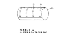
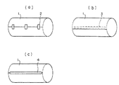
従来より、抄紙機ワインダにおいて巻取りロールにウェブ状の紙(以下、巻取り紙という)を巻取る際には、巻取り完了時に、巻端部が剥がれないように例えば接着テープで巻端を留めて固定している。図7,図8は従来の抄紙機のワインダで巻きかけられた巻取りロールの端部の固定方法を示す図であり、図7は接着テープによる固定方法を示す図、図8は帯鉄やプラスチックのバンドによる固定方法を示す図である。
【0003】
接着テープによる一般的な固定方法には、図7に示すように、短い片面接着テープ2を適宜の間隔で外側から貼り付けて留めるもの(図7(a)参照)、巻端の内側に貼った幅方向に長い両面接着テープ3で留めるもの(図7(b)参照)、巻端を外側からロールの幅方向に長い片面接着テープ4で留めるもの(図7(c)参照)がある。
【0004】
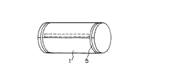
さらに、特に厚紙では外層が緩みやすいため、図8のように巻取りロール1の端部に帯鉄やプラスチックのバンド5を掛けて、巻きが緩まないように締め付けている。しかし、このようなバンド掛けは、ワインダとは別の場所にバンド掛け装置を設ける必要があり、設備費が嵩むとともに、その作業に余分の工程及び時間をかける必要がある。
【0005】
ところで、巻取りロールの巻端部をテープで留める装置は、ワインダ内で処理するものやワインダから離れた機外で処理するものなど種々あるが、作業の効率性や設備費などの面からワインダ内で処理することが望ましく、この方法として、特許第2559660号公報で巻取り紙ロールのテールシール方法(巻端処理方法)が提案されている。
【0006】
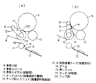
図9は、特許第2559660号公報で提案されているテールシール装置(巻端処理装置)の概略を示す模式図であり、(a)は巻取りドラムを用いて巻取り紙を巻取りロールに巻取る様子を示す図であり、(b)は巻端部で巻取り紙を切断する様子を示す図である。
このテールシール装置は、図9に示すように、一対の巻取りドラム10,10,タッチロール11,テープ貼りユニット12,アーム15,押しロール16及びカッタ17をその要部としてそなえている。
【0007】
巻取り紙8は、図9(a)に示すように、一方の巻取りドラム10を介して巻取りロール(ロール)9に巻取られる。この一方の巻取りドラム10にはアーム15の一端が巻取りドラム10の回転軸心回りに回転可能に支持されており、アーム15の他端には押しロール16が支持されている。巻取りドラム10の下方にはタッチロール11が設けられ、タッチロール11に対向してテープ貼りユニット12が設けられている。なお、カッタ17は巻取りドラム10の回転軸心回りに回転可能なアーム(図示略)により駆動され巻取り紙8に対して離接するようになっている。
【0008】
巻端部に両面接着テープ13を貼付けるテールシールにあたっては、巻取り紙8を巻取りロール9に巻取っている際に、テープ貼りユニット12の両面接着テープ13をタッチロール11に貼り付けておく。巻端部が通過するとき、タッチロール11を巻取りドラム10に押し付けると、タッチロール11上の両面接着テープ14が巻取りロール9に貼られる直前に、図9(b)に示すように、アーム15を回転し、押しロール16で巻取りロール9を押して、一方の巻取りドラム10から巻取りロール9を離す。この離れた隙間にカッタ17を作動させ巻取り紙8を切断する。巻取りロール9が更に回転すると、両面接着テープ14は押しロール16と巻取りロール9との間を通過し、巻取りロール9と押しロール14との間のニップ圧で巻端部が接着する。したがって、このテールシール装置においては、図7(b)で示すような巻端部の処理が可能である。
【0009】
【発明が解決しようとする課題】
しかしながら、巻端部を両面接着テープで留める前に巻取り紙8を切断するため、巻取り紙8の張力が保持されない状態で巻端を留めることになり、巻端部に巻弛みが生じるという課題がある。
巻弛みが生じると、紙層間をロールの径方向に締め付ける力が弱くなるため、表層部の巻きが緩み、後工程でロールを転がすなどして搬送する際に、図10に示すように表層部の紙が幅方向にずれて不揃いになり易い。このように紙が幅方向にずれたロールを縦に積んで保管する場合、このずれた部分が潰れて損紙となるため、帯鉄やプラスチックなどのバンドによりバンド掛けをして弛みが生じないようにする必要がある。しかし、このバンドは印刷工場などの最終段階では取り外す必要があり、取り外しの手間がかかると同時に、取り外し後のバンドを廃棄物として処理する必要があるため、作業効率や費用の面で負担になるという課題があった。
【0010】
本発明は、上述の課題に鑑み創案されたもので、巻取りロールの巻端部での弛みの発生を防止することができるようにした巻取りロールの巻端処理方法及び装置並びに巻取りロール製造方法及び装置を提供することを目的とする。
【0011】
【課題を解決するための手段】
上記目的を達成するために、本発明の巻取りロールの巻端処理方法は、ウェブをロールに巻取って巻取りロールを製造する際に、巻弛みが生じないように該ウェブの巻端部を該巻取りロールに接着させて固定する巻取りロールの巻端処理方法であって、該ウェブの巻取り中に該ウェブに接着部材を付着させ、次に該ウェブを巻取るための張力がかかった状態で、該接着部材の少なくとも一部で該ウェブと該巻取りロールとを接着させ、次に接着部よりも上流側の該ウェブを切断することを特徴としている(請求項1)。
【0012】
なお、該接着部材が、該ウェブの幅方向に向けて延在するように貼付された両面テープであってもよい(請求項2)。
また、該接着部材が、該ウェブの長手方向に向けて延在するように貼付された両面テープであってもよい(請求項3)。
また、本発明の巻取りロール製造方法は、上記の巻取りロールの巻端処理方法を適用して巻取りロールを製造することを特徴としている(請求項4)。
【0013】
また、本発明の巻取りロールの巻端処理装置は、ウェブをロールに巻取って巻取りロールを製造する際に、巻弛みが生じないように該ウェブの巻端部を該巻取りロールに接着させて固定する巻取りロールの巻端処理装置であって、該ウェブの巻取り中に接着部材を該ウェブに付着させる接着部材付着部と、該ウェブを巻取るための張力がかかった状態で、該接着部材の少なくとも一部で該ウェブと該巻取りロールとが接着した後に、接着部の上流側の該ウェブを切断する切断部とをそなえて構成されたことを特徴としている(請求項5)。
【0014】
さらに、本発明の巻取りロール製造装置は、上記の巻取りロールの巻端処理装置をそなえて構成されたことを特徴としている(請求項6)。
【0015】
【発明の実施の形態】
以下、図面により、本発明の実施の形態について説明する。
まず、第1実施形態について説明すると、図1〜図3は本発明の第1実施形態としての巻取りロールの巻端処理装置に関するもので、図1はその要部の構成を示す模式図であり、図2は巻端部の処理動作を示す図であり、図3はその装置及び方法によって巻取られた巻取りロールを示す模式図である。
【0016】
なお、図1,図2において、図9を用いて説明した従来の技術と同様の部位については同じ符号を付し、その説明を一部省略する。
本実施形態に係る巻取りロールの巻端処理装置は、巻取りロール製造装置にそなえられており、図1に示すように、2ドラム形式のワインダ構造を有しており、一対の巻取りドラム(給紙部)10,10,アーム15,押しロール16,カッタ(切断部)17及びテープ貼りユニット(接着部材供給部)30を構成要部としてそなえている。巻取りドラム10,アーム15,押しロール16及びカッタ17は、従来のテールシール装置と同様の構造を有している。
【0017】
テープ貼りユニット30は、一方の巻取りドラム10の下方に設けられており、供給リール32,巻取りリール33,押えロール(接着部材付着部)34,シリンダ35,テープカッタ36,ガイドロール37を要部として構成され、両面接着テープ(両面接着テープ本体と裏打ち材を貼り合せたテープ:接着部材)31をウェブ(ウェブ状の紙、以下巻取り紙という)8の流れ方向に繰り出して貼るように作用する。
【0018】
すなわち、テープ貼りユニット30では、まず、ロール状に巻いた両面接着テープ31を供給リール32に掛ける。そして、両面接着テープ31の先端部を巻戻してガイドロール37,押えロール34を経て巻取りリール33に留めておく。この後、押えロール34は、シリンダ35により駆動されて巻取りドラム10に向かって移動し、両面接着テープ本体を巻取り紙8に転移する。この際、裏打ち材は巻取りリール33に巻取られる。両面接着テープ本体が必要な長さだけ転移したら、シリンダ35を駆動して押えロール34を巻取り紙8から離し、両面接着テープ本体をテープカッタ36で切断する。このようにして、テープカッタ36で巻取り紙8に所定の長さに切断され貼付けられた両面接着テープ本体を両面接着テープ片(接着部材)21と表記する。
【0019】
図2(a)に示すように、巻端部手前でテープ貼りユニット30により、両面接着テープ片21が、その先端部分が巻取りドラム10と巻取りロール20とのニップ部100を通過するまで、即ち、巻取り紙8に張力又はニップが働いている状態で巻取り紙8が巻取りロール20本体に接着しうる程度まで、巻取り紙8の流れ方向に十分長く貼り付けられる。巻取り紙8が巻取りロール20に巻取られる際に、巻取り紙8の巻端部は両面接着テープ片21によりニップ部100で巻取りロール20にしっかりと留められる。この間、巻取り紙8には紙を巻取るための張力がかかっているため、巻端部は張力を保持したまま留められ固定されることになる。
【0020】
図2(b)に示すように、巻端の切断部が所定の位置までくると、アーム15が作動し、押しロール16が巻取りロール20を押し、カッタ17で巻取り紙8を切断する。巻取り紙8を切断すると切断部付近の巻取り紙8の張力はなくなるが、両面接着テープ片21の先端が既に巻端部に留められ固定されているので、巻端部の巻きが弛むことはない。また、両面接着テープ片21が巻取り紙8の長手方向に十分長く貼付されるため巻端部を強固に固定できるとともに、カッタ17で巻取り紙8を切断するタイミングが多少ずれても巻端処理が確実に行われる。
【0021】
このように巻端処理が行われカッタ17で切り出された後、残りの部分が巻取りロール20に巻取られ、図3に示されるようなロールとして取り出される。
本発明の第1実施形態としての巻取りロール製造装置及び方法は、上述のように構成されているので、巻取り紙8の巻端部を張力のかかった状態で留めて固定した後、上流側の巻取り紙8を切断するため、巻弛みのない巻取りロール20を得ることができる。したがって、図10に示すように、表層部の巻取り紙8が幅方向にずれて不揃いになるような不具合の発生も回避することができる。
【0022】
また、上述の作業が巻取り紙8を巻取る工程と並行して行なわれるため、新たに別の装置を用いて巻端部にテープを貼り付けて固定したり帯鉄やプラスチックなどのバンドで締め付けて補強したりする必要がないため、設備費用の削減や作業効率の向上に寄与する。
また、両面接着テープ片21が巻取り紙8の長手方向に十分長く貼付されるため巻端部を強固に固定できるとともに、カッタ17で巻取り紙8を切断するタイミングが多少ずれても巻端処理が確実に行われ、巻弛みのない巻取りロール20を得ることができる。
【0023】
そして、かかる巻取りロールの巻端処理装置及び方法を用いて巻取りロール製造装置及び方法を構成することにより、簡素な構成で巻弛みのない巻取りロールを製造することができる。
次に、本発明の第2実施形態について説明すると、図4〜図6は本発明の第2実施形態としての巻取りロール製造装置の要部を示す模式図であり、図4はその構成を示す模式図、図5はその要部の動作を示す模式図、図6はその変形例における模式図である。なお、本実施形態に係る巻取りロール製造装置においても、図9を用いて説明した従来の技術と同様の部位については同じ符号を付し、その説明を一部省略する。
【0024】
図4に示すように、本発明の第2実施形態としての巻取りロールの巻端処理装置は、1ドラム形式のワインダ構造を有しており、一つの巻取りドラム(給紙部)40及びテープ貼りユニット(接着部材供給部)30に対して、左右対称にいずれも一対の巻取りロール20,20,スタンド41,41,アーム42,42,カッタ(切断部)43,43,押えロール44,44が配設され構成されている。本装置はこのように略左右対称の構造であり、左右で対応する構成部材は同じ働きをするため、このような略左右対称に配されている部材については、一方(ここでは、左側部分)の構造及び動作について説明する。
【0025】
巻取りドラム40の両側に各スタンド41が設けられ、アーム42の一端は、スタンド41により回転可能に支持され駆動される。アーム42の他端には巻取りロール20がセンタ(回転軸)42aにより支持されており、センタ42aは図示しないモータで回転駆動されるようになっていて、巻取りロール20は、このセンタ42aを通じて回転駆動される。そして、スタンド41には、アーム42の傾き角度を調整しうる機構(図示略)がそなえられ、巻取りロール20の傾き角度を調整することにより、巻取りロール20と巻取りドラム40とが圧接するニップ部100のニップ圧がコントロールされる。また、アーム42の巻取りロール20を支えるセンタ42aは巻取りドラム40の回転を調整することでニップ部100に円周方向の力を与えて巻取り張力をコントロールするようになっている。
【0026】
巻取りドラム40の下方には、テープ貼りユニット30が設けられている。このテープ貼りユニット30は、第1実施形態と同じ構造及び機能を有する。つまり、巻端が近づくと、テープ貼りユニット30により、両面接着テープ片(接着部材)21の先端部分が巻取りドラム40と巻取りロール20とのニップ部100を通過する程度まで、即ち、巻取り紙8に張力が働いている又はニップのある状態で巻取り紙8が巻取りロール20本体に接着しうる程度まで十分長く貼り付けられ、このニップ部100で巻端部は巻取り紙8に張力が与えられた状態で巻取りロール20に留められ固定される。また、カッタ43は巻取りドラム40の回転軸と同じ回転軸を有するアーム(図示略)により進退駆動される。
【0027】
図5に示すように、巻端の切断部が所定の位置にくると、スタンド41により巻取りロール20が巻取りドラム40から離接するようにアーム42が駆動され、押えロール44が適宜のタイミングで上昇し巻端部を押える。そして、カッタ43が巻取り紙8の近くまで前進されて、巻端が切断される。切断後は、巻取り紙8に張力はかからないが、既に両面接着テープ片21の先端部が張力のある状態で貼り付けられ固定されているため、巻端部全体としての張力は十分保持されている。そして、前記第1実施形態と同様に、両面接着テープ片21が巻取り紙8の長手方向に十分長く貼付されるため巻端部を強固に固定できるとともに、カッタ43で巻取り紙8を切断するタイミングが多少ずれても巻端処理が確実に行われる。
【0028】
巻取りロール20は巻端の切断後、センタ42aで駆動されて回転し、押えロール44で残りの部分を押えて完全に巻取られる。
なお、両面接着テープ片21は、巻取りドラム40と巻取りロール20とのニップ圧で留められるかわりに、押えロール44により巻取りロール20に押えられて留められてよい。
【0029】
本発明の第2実施形態としての巻取りロール製造装置及び方法は、上述のように構成されているため、第1実施形態と同様に、巻取り紙8の巻端部を張力のかかった状態で留めて固定した後、上流側の巻取り紙8を切断するため、巻弛みのない巻取りロール20を得ることができる。
また、上述の作業が巻取り紙8を巻取る工程と並行して行なわれるため、新たに別の装置を用いて巻端部にテープを貼り付けて固定したり帯鉄やプラスチックなどのバンドで締め付けて補強したりする必要がないため、設備費用の削減や作業効率の向上に寄与する。
【0030】
また、両面接着テープ片21が巻取り紙8の長手方向に十分長く貼付されるため巻端部を強固に固定できるとともに、カッタ17で巻取り紙8を切断するタイミングが多少ずれても巻端処理が確実に行われ、巻弛みのない巻取りロール20を得ることができる。
次に、本発明の第2実施形態の変形例について図6を用いて説明すると、この変形例では、図6に示すように、押えロールがなく、巻取りロール20と巻取りドラム(給紙部)40はニップ部を設けずに互いに離れて配置されている。そして、これ以外は上記の第2実施形態と同様に構成されている。
【0031】
両面接着テープ片(接着部材)21は、センタ42aにより与えられる巻取り紙8の張力により巻取りロール20の円周部分で生じるロール中心方向の力によって貼り付けられ固定される。両面接着テープ片21の先端部分が固定された後、カッタ(切断部)43により巻端が切断されるのは、第2実施形態と同様である。
【0032】
したがって、本変形例においては、第2実施形態と同様に、巻取り紙8の巻端部を張力のかかった状態で留めて固定した後、上流側の巻取り紙8を切断するため、巻弛みのない巻取りロール20を得ることができる。
また、上述の作業が巻取り紙8を巻取る工程と並行して行なわれるため、新たに別の装置を用いて巻端部にテープを貼り付けて固定したり帯鉄やプラスチックなどのバンドで締め付けて補強したりする必要がないため、設備費用の削減や作業効率の向上に寄与する。
【0033】
次に、本発明の第3実施形態としての巻取りロール製造装置について説明する。本装置の構成は図9に示す従来のものと全く同様であるため、説明を省略する。
本実施形態では、かかる装置を用いながらカッタ17による巻取り紙8の切断時の状態が従来技術の場合と異なっている。つまり、従来技術で巻取り紙8を切断してから両面接着テープ(接着部材)14により巻取りロール9の巻端を巻取りロール9に貼付けるようにしていたが、本実施形態のものでは、両面接着テープ(接着部材)14が巻取り紙8に転移され、押しロール16により巻取りロール9に押し付けられて貼り付けられた後、巻端がカッタ(切断部)17により切断されるようになっている。したがって、本実施形態にかかる巻取りロール製造装置においては、例えば図7(b)に示すような巻端部の処理が可能であり、巻取りロール9の巻端部をはがして使用する場合に使用できない巻端部の面積を最小限に抑えることができるようになっている。
【0034】
本発明の第3実施形態としての巻取りロール製造装置は、上述のように構成されているので、第1実施形態及び第2実施形態と同様に、巻取り紙8の巻端部を張力のかかった状態で留めて固定した後、上流側の巻取り紙8を切断するため、巻弛みのない巻取りロール20を得ることができる。
また、上述の作業が巻取り紙8を巻取る工程と並行して行なわれるため、新たに別の装置を用いて巻端部にテープを貼り付けて固定したり帯鉄やプラスチックなどのバンドで締め付けて補強したりする必要がないため、設備費用の削減や作業効率の向上に寄与する。
【0035】
さらに、両面接着テープ14が巻取り紙8の幅方向に貼付されているため、巻端部をはがして使う場合に使用できない巻端部の面積を最小限に抑えることができる。
なお、本発明は上述の実施形態に限定されるものではなく、本発明の趣旨を逸脱しない範囲で種々変形して実施することができる。
【0036】
例えば、接着部材を付着させる方法として、両面接着テープを貼り付ける代わりに、例えば印刷技術により接着部材を塗布する方法でもよい。
また、接着部材(両面接着テープ)は巻取りロールの幅方向に延在する方向に貼付してもよいし、巻取りロールの長手方向に延在する方向に貼付してもよい。幅方向に延在する方向に貼付した場合は、巻取りロールをはがして使用する際に、損紙となる巻端部の面積を最小限に抑えることができ、また、長手方向に延在する方向に貼付した場合には、巻端部をより強固に接着できるとともにカッタで巻取り紙を切断するタイミングがずれても巻端処理を確実に行なうことができる。
【0037】
また、ウェブ状のものをロールに巻取る場合に広く適用でき、紙の巻取りに限定されるものではない。
【0038】
【発明の効果】
以上、詳述したように本発明によれば、接着部材の少なくとも一部でウェブが巻取りロールと接着した状態で接着部よりも上流側のウェブを切断するため、ウェブの巻端部が張力のかかった状態で留められ、巻弛みの発生を確実に防ぐことができる(請求項1,4,5,6)。
【0039】
また、巻端部に接着部材がウェブの幅方向に向けて延在するように貼付されることにより、はがして使用する場合に使用できない巻端部の面積を最小限に抑えることができる(請求項2)。
接着部材がウェブの長手方向に向けて延在するように貼付された場合、巻端部をより強固に接着できるとともに、ウェブを切断するタイミングが多少ずれても巻端部の処理を確実に行なうことができる(請求項3)。
【図面の簡単な説明】
【図1】本発明の第1実施形態における巻取りロール製造装置の要部の構成を示す模式図である。
【図2】本発明の第1実施形態における巻取りロール製造装置の要部を拡大して示す模式的図であり、(a)は両面接着テープ(接着部材)により巻取り紙と巻取りロールが貼り付けられる様子をあらわす図であり、(b)は巻取り紙の巻端がカッタ(切断部)により切断される様子をあらわす図である。
【図3】本発明の第1実施形態における巻取りロール製造装置により製造された巻取りロールを示す模式的図である。
【図4】本発明の第2実施形態における巻取りロール製造装置の要部の構成を示す模式図である。
【図5】本発明の第2実施形態おける巻取りロール製造装置の要部を拡大して示す模式図であり、図2(b)に対応する図である。
【図6】本発明の第2実施形態の変形例おける巻取りロール製造装置の要部を拡大して示す模式図であり、図5に対応する図である。
【図7】一般的な巻取りロールの巻端部の固定方法を示す模式図であり、(a)は巻端部を短い片面接着テープを適宜の間隔で外側から貼り付けて固定した図、(b)は巻端の内側に貼った巻取り紙の幅方向に長い両面接着テープで固定した図、(c)は巻端を外側からロールの幅方向に長い片面接着テープで固定した図である。
【図8】巻取りロールの端部を帯鉄やプラスチックのバンドで締め付けて固定した図である。
【図9】従来のテールシール装置を示す模式図であり、(a)はその要部の構成を示す図であり、(b)はカッタにより巻取り紙の巻端部が切断される様子を示す模式図である。
【図10】巻弛みによって生じる、巻取りロール表層部の巻取り紙のずれを示す模式図である。
【符号の説明】
1 巻取りロール
2 片面接着テープ
3 両面接着テープ
4 片面接着テープ
5 帯鉄やプラスチックのバンド
8 巻取り紙
9 巻取りロール
10 巻取りドラム(給紙部)
11 タッチロール(接着部材付着部)
12 テープ貼りユニット(接着部材供給部)
13,14 両面接着テープ(接着部材)
15 アーム
16 押しロール
17 カッタ(切断部)
20 巻取りロール
21 両面接着テープ片(接着部材)
30 テープ貼りユニット(接着部材供給部)
31 両面接着テープ(接着部材)
32 供給リール
33 巻取りリール
34 押えロール(接着部材付着部)
35 シリンダ
36 テープカッタ
37 ガイドロール
40 巻取りドラム(給紙部)
41 スタンド
42 アーム
42a センタ
43 カッタ(切断部)
44 押えロール
100 ニップ部[0001]
TECHNICAL FIELD OF THE INVENTION
The present invention relates to a method and an apparatus for treating a winding end portion of a web so that there is no slack when manufacturing a winding roll by winding a web, and a winding roll manufacturing method and an apparatus using the method. The present invention relates to a winding roll manufacturing apparatus having the same.
[0002]
[Prior art]
2. Description of the Related Art Conventionally, when winding a web-shaped paper (hereinafter referred to as a “wound paper”) on a take-up roll in a paper machine winder, when winding is completed, the winding end is, for example, adhered with an adhesive tape so that the winding end is not peeled. Fastened and fixed. 7 and 8 are views showing a method of fixing an end of a take-up roll wound by a conventional paper machine winder, FIG. 7 is a view showing a method of fixing with an adhesive tape, and FIG. It is a figure which shows the fixing method with a plastic band.
[0003]
As shown in FIG. 7, a general fixing method using an adhesive tape is to attach a short one-sided
[0004]
Further, since the outer layer is easily loosened particularly in the case of cardboard, as shown in FIG. 8, a
[0005]
By the way, there are various types of devices for fixing the winding end portion of the winding roll with tape, such as a device for processing inside the winder and a device for processing outside the machine away from the winder, but from the viewpoint of work efficiency and equipment cost, etc. In this case, a tail sealing method (winding end processing method) for a roll of paper is proposed in Japanese Patent No. 2559660.
[0006]
FIG. 9 is a schematic diagram showing an outline of a tail seal device (winding end processing device) proposed in Japanese Patent No. 2559660, and FIG. 9A shows a winding drum and a winding paper used as a winding roll. It is a figure which shows a mode that winding is performed, and (b) is a figure which shows a mode that a web is cut | disconnected at a winding end part.
As shown in FIG. 9, the tail seal device includes a pair of
[0007]
The take-
[0008]
In the tail seal where the double-sided
[0009]
[Problems to be solved by the invention]
However, since the winding
When the looseness of the roll occurs, the force for tightening the paper layer in the radial direction of the roll is weakened. Therefore, the winding of the surface layer is loosened. Paper is likely to be misaligned due to a shift in the width direction. When the paper is vertically stacked and stored in a roll in which the paper is displaced in the width direction, the displaced portion is crushed and becomes a waste sheet. You need to do that. However, this band must be removed at the final stage, such as in a printing factory, which is time-consuming and requires disposal of the removed band as waste, which puts a burden on work efficiency and costs. There was a problem.
[0010]
SUMMARY OF THE INVENTION The present invention has been made in view of the above-described problems, and has a winding roll processing method and apparatus, and a winding roll capable of preventing occurrence of loosening at a winding end of the winding roll. It is an object to provide a manufacturing method and an apparatus.
[0011]
[Means for Solving the Problems]
In order to achieve the above object, the winding end treatment method of the winding roll according to the present invention is configured such that when the web is wound on a roll to produce a winding roll, the winding end of the web is prevented from being loosened. A winding end treatment method of a winding roll in which the web is wound with the adhesive member, and then the tension for winding the web is reduced. When under, at least part of the adhesive member adhered to the said web and the take-up roll, and then characterized by cutting the web upstream of the adhesive portion (claim 1) .
[0012]
Note that the adhesive member may be a double-sided tape attached so as to extend in the width direction of the web (claim 2).
Further, the adhesive member may be a double-sided tape attached so as to extend in the longitudinal direction of the web (claim 3).
Further, a winding roll manufacturing method of the present invention is characterized in that a winding roll is manufactured by applying the winding end processing method of the winding roll described above (claim 4).
[0013]
Further, the winding end treatment device of the winding roll of the present invention, when manufacturing the winding roll by winding the web on the roll, the winding end portion of the web to the winding roll so that the winding does not loosen. A winding end treatment device for a winding roll for bonding and fixing, wherein an adhesive member attaching portion for attaching an adhesive member to the web during winding of the web , and a state in which tension for winding the web is applied in, after the said web and the take-up roll is bonded with at least a portion of the adhesive member, it is characterized in that it is constructed to include a cutting portion for cutting the upstream side of the web of the contact attachment part ( Claim 5).
[0014]
Furthermore, the winding roll manufacturing apparatus of the present invention is characterized by being provided with the winding end processing apparatus for the winding roll described above (claim 6).
[0015]
BEST MODE FOR CARRYING OUT THE INVENTION
Hereinafter, embodiments of the present invention will be described with reference to the drawings.
First, a first embodiment will be described. FIGS. 1 to 3 relate to a winding end processing apparatus of a winding roll as a first embodiment of the present invention, and FIG. 1 is a schematic diagram showing a configuration of a main part thereof. FIG. 2 is a diagram showing a processing operation of a winding end portion, and FIG. 3 is a schematic diagram showing a winding roll wound by the apparatus and method.
[0016]
In FIGS. 1 and 2, the same parts as those of the conventional technique described with reference to FIG. 9 are denoted by the same reference numerals, and the description thereof will be partially omitted.
The winding roll end processing apparatus according to the present embodiment is provided in a winding roll manufacturing apparatus, and has a two-drum type winder structure as shown in FIG. (Paper feeding unit) 10, 10,
[0017]
The
[0018]
That is, in the
[0019]
As shown in FIG. 2A, the double-sided
[0020]
As shown in FIG. 2B, when the cut portion at the winding end reaches a predetermined position, the
[0021]
After the winding end processing is performed and cut out by the
Takeup roll manufacturing apparatus and method according to the first embodiment of the present invention, which is configured as described above, after fixing hold the winding end portion of the
[0022]
In addition, since the above-mentioned operation is performed in parallel with the step of winding the winding
In addition, since the double-sided
[0023]
By configuring the winding roll manufacturing apparatus and method using the winding roll end processing apparatus and method, a winding roll having a simple configuration and no winding slack can be manufactured.
Next, a second embodiment of the present invention will be described. FIGS. 4 to 6 are schematic views showing a main part of a winding roll manufacturing apparatus as a second embodiment of the present invention, and FIG. FIG. 5 is a schematic diagram showing the operation of the main part, and FIG. 6 is a schematic diagram in a modification. In the winding roll manufacturing apparatus according to this embodiment, the same parts as those in the related art described with reference to FIG. 9 are denoted by the same reference numerals, and the description thereof is partially omitted.
[0024]
As shown in FIG. 4, the winding end processing device of the winding roll according to the second embodiment of the present invention has a one-drum type winder structure, and includes one winding drum (feeding unit) 40 and A pair of take-up rolls 20, 20, stands 41, 41,
[0025]
Each stand 41 is provided on both sides of the winding
[0026]
Below the winding
[0027]
As shown in FIG. 5, when the cut portion at the winding end is at a predetermined position, the
[0028]
After the winding end is cut, the winding
Note that the double-sided
[0029]
Since the take-up roll manufacturing apparatus and method according to the second embodiment of the present invention are configured as described above, the take-up end of the take-up
In addition, since the above-mentioned operation is performed in parallel with the step of winding the winding
[0030]
In addition, since the double-sided
Next, a modified example of the second embodiment of the present invention will be described with reference to FIG. 6. In this modified example, as shown in FIG. The
[0031]
The double-sided adhesive tape piece (adhesive member) 21 is affixed and fixed by a force in a roll center direction generated in a circumferential portion of the winding
[0032]
Accordingly, in this modification, similarly to the second embodiment, after fixing hold the winding end portion of the
In addition, since the above-mentioned operation is performed in parallel with the step of winding the winding
[0033]
Next, a winding roll manufacturing apparatus as a third embodiment of the present invention will be described. The configuration of this apparatus is exactly the same as the conventional one shown in FIG.
In the present embodiment, the state of cutting the
[0034]
Since the winding roll manufacturing apparatus as the third embodiment of the present invention is configured as described above, similarly to the first embodiment and the second embodiment, the winding end of the winding
In addition, since the above-mentioned operation is performed in parallel with the step of winding the winding
[0035]
Further, since the double-sided
Note that the present invention is not limited to the above-described embodiment, and can be implemented with various modifications without departing from the spirit of the present invention.
[0036]
For example, as a method of attaching the adhesive member, a method of applying the adhesive member by, for example, a printing technique may be used instead of attaching the double-sided adhesive tape.
The adhesive member (double-sided adhesive tape) may be attached in a direction extending in the width direction of the winding roll, or may be attached in a direction extending in the longitudinal direction of the winding roll. When affixed in the direction extending in the width direction, the area of the winding end portion serving as a waste sheet can be minimized when the take-up roll is peeled and used, and also extends in the longitudinal direction. In the case of sticking in the direction, the winding end portion can be more firmly adhered and the winding end processing can be surely performed even if the timing of cutting the web with the cutter is shifted.
[0037]
Further, the present invention can be widely applied to a case where a web is wound on a roll, and is not limited to winding a paper.
[0038]
【The invention's effect】
As described in detail above, according to the present invention, at least a part of the adhesive member cuts the web upstream of the bonding portion in a state where the web is bonded to the take-up roll. It is possible to reliably prevent the occurrence of loosening of the winding (
[0039]
Further, since the adhesive member is attached to the winding end portion so as to extend in the width direction of the web, the area of the winding end portion that cannot be used when peeled and used can be minimized. Item 2).
When the adhesive member is stuck so as to extend in the longitudinal direction of the web, the winding end can be more firmly bonded, and the processing of the winding end is reliably performed even if the timing of cutting the web is slightly shifted. (Claim 3).
[Brief description of the drawings]
FIG. 1 is a schematic diagram illustrating a configuration of a main part of a winding roll manufacturing apparatus according to a first embodiment of the present invention.
FIG. 2 is an enlarged schematic view showing a main part of a take-up roll manufacturing apparatus according to a first embodiment of the present invention, wherein (a) is a take-up paper and a take-up roll using a double-sided adhesive tape (adhesive member); FIG. 4B is a diagram illustrating a state in which the paper is adhered, and FIG. 4B is a diagram illustrating a state in which the winding end of the web is cut by a cutter (cutting portion).
FIG. 3 is a schematic diagram illustrating a winding roll manufactured by the winding roll manufacturing apparatus according to the first embodiment of the present invention.
FIG. 4 is a schematic diagram illustrating a configuration of a main part of a take-up roll manufacturing apparatus according to a second embodiment of the present invention.
FIG. 5 is an enlarged schematic view showing a main part of a winding roll manufacturing apparatus according to a second embodiment of the present invention, and is a view corresponding to FIG. 2 (b).
FIG. 6 is an enlarged schematic view illustrating a main part of a winding roll manufacturing apparatus according to a modification of the second embodiment of the present invention, and is a view corresponding to FIG. 5;
FIG. 7 is a schematic view showing a method of fixing a winding end portion of a general winding roll, wherein FIG. 7 (a) is a diagram in which a short single-sided adhesive tape is attached to the winding end portion at an appropriate interval from the outside and fixed. (B) is a diagram in which the winding paper attached to the inside of the winding end is fixed with a double-sided adhesive tape that is long in the width direction, and (c) is a diagram in which the winding end is fixed with a single-sided adhesive tape that is long in the width direction of the roll from the outside. is there.
FIG. 8 is a diagram in which the end of the winding roll is fastened and fixed with a steel band or a plastic band.
9A and 9B are schematic diagrams showing a conventional tail seal device, wherein FIG. 9A is a diagram showing a configuration of a main part thereof, and FIG. 9B is a diagram showing a state in which a winding end of a web is cut by a cutter. FIG.
FIG. 10 is a schematic diagram showing a displacement of a roll of paper on a winding roll surface layer caused by loosening of the roll.
[Explanation of symbols]
REFERENCE SIGNS LIST 1 take-
11 Touch roll (adhesive member attachment part)
12 Tape application unit (adhesive supply unit)
13,14 Double-sided adhesive tape (adhesive member)
15
20 Take-
30 Tape application unit (adhesive supply unit)
31 Double-sided adhesive tape (adhesive member)
32
35
41
44
Claims (6)
該ウェブの巻取り中に該ウェブに接着部材を付着させ、
次に該ウェブを巻取るための張力がかかった状態で、該接着部材の少なくとも一部で該ウェブと該巻取りロールとを接着させ、
次に接着部よりも上流側の該ウェブを切断することを特徴とする、巻取りロールの巻端処理方法。A winding end treatment method for a winding roll in which a winding end of the web is adhered and fixed to the winding roll so that the web does not become loose when the web is wound around the roll to produce the winding roll. hand,
Attaching an adhesive member to the web during winding of the web ;
Then under tension for winding the web to bond the said web and the take-up roll at least part of the adhesive member,
Then characterized and Turkey to cut the upstream side of the web than the adhesive portion, winding end processing method of the take-up roll.
該ウェブの巻取り中に接着部材を該ウェブに付着させる接着部材付着部と、
該ウェブを巻取るための張力がかかった状態で、該接着部材の少なくとも一部で該ウェブと該巻取りロールとが接着した後に、接着部の上流側の該ウェブを切断する切断部とをそなえて構成されたことを特徴とする、巻取りロールの巻端処理装置。A winding end treatment device for a winding roll, wherein the winding end of the web is adhered and fixed to the winding roll so that the web does not become loose when winding the web around the roll to produce the winding roll. hand,
An adhesive member attaching portion for attaching an adhesive member to the web during winding of the web ;
Under tension for winding the web, at least a portion of the adhesive member after the said web and the take-up roll is adhered, a cutting unit for cutting the upstream side of the web of the contact attachment part characterized in that it is configured to include a winding end processor of the take-up roll.
Priority Applications (1)
| Application Number | Priority Date | Filing Date | Title |
|---|---|---|---|
| JP2001174728A JP3564429B2 (en) | 2001-06-08 | 2001-06-08 | Winding roll end processing method and apparatus, and winding roll manufacturing method and apparatus |
Applications Claiming Priority (1)
| Application Number | Priority Date | Filing Date | Title |
|---|---|---|---|
| JP2001174728A JP3564429B2 (en) | 2001-06-08 | 2001-06-08 | Winding roll end processing method and apparatus, and winding roll manufacturing method and apparatus |
Publications (2)
| Publication Number | Publication Date |
|---|---|
| JP2002362800A JP2002362800A (en) | 2002-12-18 |
| JP3564429B2 true JP3564429B2 (en) | 2004-09-08 |
Family
ID=19015972
Family Applications (1)
| Application Number | Title | Priority Date | Filing Date |
|---|---|---|---|
| JP2001174728A Expired - Fee Related JP3564429B2 (en) | 2001-06-08 | 2001-06-08 | Winding roll end processing method and apparatus, and winding roll manufacturing method and apparatus |
Country Status (1)
| Country | Link |
|---|---|
| JP (1) | JP3564429B2 (en) |
Families Citing this family (3)
| Publication number | Priority date | Publication date | Assignee | Title |
|---|---|---|---|---|
| JP5552840B2 (en) * | 2010-03-02 | 2014-07-16 | 宇部興産株式会社 | Manufacturing method and storage method of resin film roll |
| JP5552841B2 (en) * | 2010-03-02 | 2014-07-16 | 宇部興産株式会社 | Manufacturing method of resin film roll |
| CN110239989A (en) * | 2019-06-20 | 2019-09-17 | 溧阳嘉拓智能设备有限公司 | Multi-function coil material trailing edge automatic punching, fitting, standby glue, cutting means and method |
-
2001
- 2001-06-08 JP JP2001174728A patent/JP3564429B2/en not_active Expired - Fee Related
Also Published As
| Publication number | Publication date |
|---|---|
| JP2002362800A (en) | 2002-12-18 |
Similar Documents
| Publication | Publication Date | Title |
|---|---|---|
| JP4616160B2 (en) | Sheet sticking device and sheet sticking method | |
| JPH0781828A (en) | Equipment and method to affix adhesive tape | |
| JP4507199B2 (en) | Web joining apparatus and method | |
| JPH0577980A (en) | Connection structure, connection piece, connection device and method for start end of belt-like body take-up roll | |
| JP4861917B2 (en) | Sheet sticking device and sheet sticking method | |
| JP3564429B2 (en) | Winding roll end processing method and apparatus, and winding roll manufacturing method and apparatus | |
| JPH05238609A (en) | Pre-prepared paster pattern | |
| JP2005280008A (en) | Tape cassette | |
| JP3600388B2 (en) | Double-sided adhesive tape application device | |
| JP5117919B2 (en) | Feeding device and sheet sticking device | |
| JP3939043B2 (en) | Web connection device | |
| JP2001240029A (en) | Taking up method for label seal and its device | |
| US20030071161A1 (en) | Method of winding sheet web coated with pressure-sensitive adhesive | |
| JPH09321490A (en) | Method and device for winding-up carrier tape | |
| MXPA05000542A (en) | Process and device for reeling a paper web. | |
| JPH10157894A (en) | Double-sided adhesive tape sticking device | |
| JP2570834B2 (en) | Web supply device and web supply method | |
| JP2009078890A (en) | Automatic splicing device | |
| JP4420996B2 (en) | Web supply roll exchange method and web supply apparatus | |
| JP2003128027A (en) | Apparatus and method for joining label automatically in labeling machine | |
| JP2583158B2 (en) | Method and apparatus for connecting thin film roll | |
| JPH0511246Y2 (en) | ||
| JP2006151653A (en) | Winding device | |
| JPH11124110A (en) | Continuous paper splice tape and continuous paper | |
| JP2000143047A (en) | Pasting tool |
Legal Events
| Date | Code | Title | Description |
|---|---|---|---|
| A131 | Notification of reasons for refusal |
Free format text: JAPANESE INTERMEDIATE CODE: A131 Effective date: 20031224 |
|
| A521 | Written amendment |
Free format text: JAPANESE INTERMEDIATE CODE: A523 Effective date: 20040223 |
|
| TRDD | Decision of grant or rejection written | ||
| A01 | Written decision to grant a patent or to grant a registration (utility model) |
Free format text: JAPANESE INTERMEDIATE CODE: A01 Effective date: 20040518 |
|
| A61 | First payment of annual fees (during grant procedure) |
Free format text: JAPANESE INTERMEDIATE CODE: A61 Effective date: 20040607 |
|
| FPAY | Renewal fee payment (event date is renewal date of database) |
Free format text: PAYMENT UNTIL: 20080611 Year of fee payment: 4 |
|
| S111 | Request for change of ownership or part of ownership |
Free format text: JAPANESE INTERMEDIATE CODE: R313113 |
|
| R350 | Written notification of registration of transfer |
Free format text: JAPANESE INTERMEDIATE CODE: R350 |
|
| FPAY | Renewal fee payment (event date is renewal date of database) |
Free format text: PAYMENT UNTIL: 20080611 Year of fee payment: 4 |
|
| FPAY | Renewal fee payment (event date is renewal date of database) |
Free format text: PAYMENT UNTIL: 20090611 Year of fee payment: 5 |
|
| FPAY | Renewal fee payment (event date is renewal date of database) |
Free format text: PAYMENT UNTIL: 20090611 Year of fee payment: 5 |
|
| FPAY | Renewal fee payment (event date is renewal date of database) |
Free format text: PAYMENT UNTIL: 20100611 Year of fee payment: 6 |
|
| FPAY | Renewal fee payment (event date is renewal date of database) |
Free format text: PAYMENT UNTIL: 20110611 Year of fee payment: 7 |
|
| FPAY | Renewal fee payment (event date is renewal date of database) |
Free format text: PAYMENT UNTIL: 20110611 Year of fee payment: 7 |
|
| FPAY | Renewal fee payment (event date is renewal date of database) |
Free format text: PAYMENT UNTIL: 20120611 Year of fee payment: 8 |
|
| FPAY | Renewal fee payment (event date is renewal date of database) |
Free format text: PAYMENT UNTIL: 20130611 Year of fee payment: 9 |
|
| LAPS | Cancellation because of no payment of annual fees |