EP0864453B2 - Luftfeder für Luftfederachsen - Google Patents
Luftfeder für Luftfederachsen Download PDFInfo
- Publication number
- EP0864453B2 EP0864453B2 EP98104218A EP98104218A EP0864453B2 EP 0864453 B2 EP0864453 B2 EP 0864453B2 EP 98104218 A EP98104218 A EP 98104218A EP 98104218 A EP98104218 A EP 98104218A EP 0864453 B2 EP0864453 B2 EP 0864453B2
- Authority
- EP
- European Patent Office
- Prior art keywords
- plunger
- plunger piston
- air spring
- cover
- secured
- Prior art date
- Legal status (The legal status is an assumption and is not a legal conclusion. Google has not performed a legal analysis and makes no representation as to the accuracy of the status listed.)
- Expired - Lifetime
Links
Images

Classifications
-
- F—MECHANICAL ENGINEERING; LIGHTING; HEATING; WEAPONS; BLASTING
- F16—ENGINEERING ELEMENTS AND UNITS; GENERAL MEASURES FOR PRODUCING AND MAINTAINING EFFECTIVE FUNCTIONING OF MACHINES OR INSTALLATIONS; THERMAL INSULATION IN GENERAL
- F16F—SPRINGS; SHOCK-ABSORBERS; MEANS FOR DAMPING VIBRATION
- F16F9/00—Springs, vibration-dampers, shock-absorbers, or similarly-constructed movement-dampers using a fluid or the equivalent as damping medium
- F16F9/02—Springs, vibration-dampers, shock-absorbers, or similarly-constructed movement-dampers using a fluid or the equivalent as damping medium using gas only or vacuum
- F16F9/04—Springs, vibration-dampers, shock-absorbers, or similarly-constructed movement-dampers using a fluid or the equivalent as damping medium using gas only or vacuum in a chamber with a flexible wall
- F16F9/05—Springs, vibration-dampers, shock-absorbers, or similarly-constructed movement-dampers using a fluid or the equivalent as damping medium using gas only or vacuum in a chamber with a flexible wall the flexible wall being of the rolling diaphragm type
- F16F9/057—Springs, vibration-dampers, shock-absorbers, or similarly-constructed movement-dampers using a fluid or the equivalent as damping medium using gas only or vacuum in a chamber with a flexible wall the flexible wall being of the rolling diaphragm type characterised by the piston
-
- B—PERFORMING OPERATIONS; TRANSPORTING
- B60—VEHICLES IN GENERAL
- B60G—VEHICLE SUSPENSION ARRANGEMENTS
- B60G11/00—Resilient suspensions characterised by arrangement, location or kind of springs
- B60G11/26—Resilient suspensions characterised by arrangement, location or kind of springs having fluid springs only, e.g. hydropneumatic springs
- B60G11/28—Resilient suspensions characterised by arrangement, location or kind of springs having fluid springs only, e.g. hydropneumatic springs characterised by means specially adapted for attaching the spring to axle or sprung part of the vehicle
-
- B—PERFORMING OPERATIONS; TRANSPORTING
- B60—VEHICLES IN GENERAL
- B60G—VEHICLE SUSPENSION ARRANGEMENTS
- B60G11/00—Resilient suspensions characterised by arrangement, location or kind of springs
- B60G11/32—Resilient suspensions characterised by arrangement, location or kind of springs having springs of different kinds
- B60G11/34—Resilient suspensions characterised by arrangement, location or kind of springs having springs of different kinds including leaf springs
- B60G11/46—Resilient suspensions characterised by arrangement, location or kind of springs having springs of different kinds including leaf springs and also fluid springs
- B60G11/465—Resilient suspensions characterised by arrangement, location or kind of springs having springs of different kinds including leaf springs and also fluid springs with a flexible wall
-
- F—MECHANICAL ENGINEERING; LIGHTING; HEATING; WEAPONS; BLASTING
- F16—ENGINEERING ELEMENTS AND UNITS; GENERAL MEASURES FOR PRODUCING AND MAINTAINING EFFECTIVE FUNCTIONING OF MACHINES OR INSTALLATIONS; THERMAL INSULATION IN GENERAL
- F16F—SPRINGS; SHOCK-ABSORBERS; MEANS FOR DAMPING VIBRATION
- F16F9/00—Springs, vibration-dampers, shock-absorbers, or similarly-constructed movement-dampers using a fluid or the equivalent as damping medium
- F16F9/32—Details
- F16F9/3207—Constructional features
-
- B—PERFORMING OPERATIONS; TRANSPORTING
- B60—VEHICLES IN GENERAL
- B60G—VEHICLE SUSPENSION ARRANGEMENTS
- B60G2200/00—Indexing codes relating to suspension types
- B60G2200/30—Rigid axle suspensions
- B60G2200/31—Rigid axle suspensions with two trailing arms rigidly connected to the axle
-
- B—PERFORMING OPERATIONS; TRANSPORTING
- B60—VEHICLES IN GENERAL
- B60G—VEHICLE SUSPENSION ARRANGEMENTS
- B60G2202/00—Indexing codes relating to the type of spring, damper or actuator
- B60G2202/10—Type of spring
- B60G2202/11—Leaf spring
- B60G2202/112—Leaf spring longitudinally arranged
-
- B—PERFORMING OPERATIONS; TRANSPORTING
- B60—VEHICLES IN GENERAL
- B60G—VEHICLE SUSPENSION ARRANGEMENTS
- B60G2202/00—Indexing codes relating to the type of spring, damper or actuator
- B60G2202/10—Type of spring
- B60G2202/14—Plastic spring, e.g. rubber
- B60G2202/143—Plastic spring, e.g. rubber subjected to compression
-
- B—PERFORMING OPERATIONS; TRANSPORTING
- B60—VEHICLES IN GENERAL
- B60G—VEHICLE SUSPENSION ARRANGEMENTS
- B60G2202/00—Indexing codes relating to the type of spring, damper or actuator
- B60G2202/10—Type of spring
- B60G2202/15—Fluid spring
- B60G2202/152—Pneumatic spring
-
- B—PERFORMING OPERATIONS; TRANSPORTING
- B60—VEHICLES IN GENERAL
- B60G—VEHICLE SUSPENSION ARRANGEMENTS
- B60G2204/00—Indexing codes related to suspensions per se or to auxiliary parts
- B60G2204/10—Mounting of suspension elements
- B60G2204/12—Mounting of springs or dampers
- B60G2204/126—Mounting of pneumatic springs
-
- B—PERFORMING OPERATIONS; TRANSPORTING
- B60—VEHICLES IN GENERAL
- B60G—VEHICLE SUSPENSION ARRANGEMENTS
- B60G2204/00—Indexing codes related to suspensions per se or to auxiliary parts
- B60G2204/40—Auxiliary suspension parts; Adjustment of suspensions
- B60G2204/43—Fittings, brackets or knuckles
-
- B—PERFORMING OPERATIONS; TRANSPORTING
- B60—VEHICLES IN GENERAL
- B60G—VEHICLE SUSPENSION ARRANGEMENTS
- B60G2204/00—Indexing codes related to suspensions per se or to auxiliary parts
- B60G2204/40—Auxiliary suspension parts; Adjustment of suspensions
- B60G2204/44—Centering or positioning means
-
- B—PERFORMING OPERATIONS; TRANSPORTING
- B60—VEHICLES IN GENERAL
- B60G—VEHICLE SUSPENSION ARRANGEMENTS
- B60G2204/00—Indexing codes related to suspensions per se or to auxiliary parts
- B60G2204/40—Auxiliary suspension parts; Adjustment of suspensions
- B60G2204/45—Stops limiting travel
- B60G2204/4502—Stops limiting travel using resilient buffer
-
- B—PERFORMING OPERATIONS; TRANSPORTING
- B60—VEHICLES IN GENERAL
- B60G—VEHICLE SUSPENSION ARRANGEMENTS
- B60G2206/00—Indexing codes related to the manufacturing of suspensions: constructional features, the materials used, procedures or tools
- B60G2206/01—Constructional features of suspension elements, e.g. arms, dampers, springs
- B60G2206/40—Constructional features of dampers and/or springs
- B60G2206/42—Springs
-
- B—PERFORMING OPERATIONS; TRANSPORTING
- B60—VEHICLES IN GENERAL
- B60G—VEHICLE SUSPENSION ARRANGEMENTS
- B60G2206/00—Indexing codes related to the manufacturing of suspensions: constructional features, the materials used, procedures or tools
- B60G2206/01—Constructional features of suspension elements, e.g. arms, dampers, springs
- B60G2206/40—Constructional features of dampers and/or springs
- B60G2206/42—Springs
- B60G2206/424—Plunger or top retainer construction for bellows or rolling lobe type air springs
-
- B—PERFORMING OPERATIONS; TRANSPORTING
- B60—VEHICLES IN GENERAL
- B60G—VEHICLE SUSPENSION ARRANGEMENTS
- B60G2206/00—Indexing codes related to the manufacturing of suspensions: constructional features, the materials used, procedures or tools
- B60G2206/01—Constructional features of suspension elements, e.g. arms, dampers, springs
- B60G2206/70—Materials used in suspensions
- B60G2206/71—Light weight materials
- B60G2206/7101—Fiber-reinforced plastics [FRP]
-
- B—PERFORMING OPERATIONS; TRANSPORTING
- B60—VEHICLES IN GENERAL
- B60G—VEHICLE SUSPENSION ARRANGEMENTS
- B60G2206/00—Indexing codes related to the manufacturing of suspensions: constructional features, the materials used, procedures or tools
- B60G2206/01—Constructional features of suspension elements, e.g. arms, dampers, springs
- B60G2206/70—Materials used in suspensions
- B60G2206/71—Light weight materials
- B60G2206/7104—Thermoplastics
-
- F—MECHANICAL ENGINEERING; LIGHTING; HEATING; WEAPONS; BLASTING
- F16—ENGINEERING ELEMENTS AND UNITS; GENERAL MEASURES FOR PRODUCING AND MAINTAINING EFFECTIVE FUNCTIONING OF MACHINES OR INSTALLATIONS; THERMAL INSULATION IN GENERAL
- F16F—SPRINGS; SHOCK-ABSORBERS; MEANS FOR DAMPING VIBRATION
- F16F2230/00—Purpose; Design features
- F16F2230/0047—Measuring, indicating
Definitions
- the invention relates to an air spring for air suspension axles according to the preamble of claim 1.
- a generic air spring is out of the DE 42 13 676 A1 known.
- the plunger made of plastic a plate is inserted or incorporated, on the angled vertical support is formed. While the plate is supported directly on the trailing arm, the support is flush in a slightly conical recording of the plunger, so that can be derived by means of the support, the high unactuated air spring mechanical forces in a direct way in the trailing arm.
- the support is not centrally located, but eccentric in the plunger, this can be fixed in different positions on the vehicle part to be mitigated.
- the invention has for its object to provide an air spring for air spring axles of the type mentioned, which is simple and inexpensive to produce and beyond overcomes the above-mentioned disadvantages.
- the inventively designed air spring can on the from DE 31 47 231 C1 be omitted known base plate, which is why the assembly of the air spring is simple and inexpensive feasible due to the lack of step of connecting the bottom plate with the plunger.
- the omission of the known from the prior art floor plate means a reduction in the unsprung masses of the axle, whereby the payload of a vehicle equipped with such an air spring vehicle can be increased.
- the downwardly open design of the plunger allows a complete exchange of air inside the plunger and thus avoids the formation of a local there may be corrosive atmosphere.
- the provided with a ribbing in the form of a plurality of substantially radial webs plunger is made of plastic and preferably glass fiber reinforced plastic. Such plastics are characterized in that they have good strength and stability properties at a low weight and high corrosion resistance.
- the plunger z. Example be designed as an extruded, which turns out to be particularly advantageous in practice, since then the profile can be produced as "by the meter", from which subsequently profile sections can be separated in any desired length. In this way, plungers of different lengths manufacturing technology can be produced very easily.
- the plunger can be produced as an injection molded part. This embodiment of the plunger also allows the production of profiles with conical surfaces and the formation of shoulders and indentations on the profile of the plunger.
- a holding plate used, preferably a cast or forged plate. This retaining plate accommodates the fastening means for securing the plunger to the trailing arm.
- the plunger has a cross-section production-optimized profile with an annular lateral surface and a central support body, wherein the support body and lateral surface are connected to each other via the substantially radially extending webs.
- the lateral surface of the plunger may be formed with only a small wall thickness, as this must take no supporting forces.
- the cylindrical outer surface serves exclusively as a rolling surface for the rolling bellows.
- a central support body for receiving the weight forces in vented air spring can be used.
- air spring axis is between a part of a vehicle frame 1 and a console 2 pivotally articulated trailing arm 3 for an axle 4 an air spring 5 installed.
- the air spring 5 consists in principle of a fixed to the vehicle frame 1 cover 6, a rolling bellows 7 and a trailing arm fixed plunger 8. On the lid side of the rolling bellows 7, for example via a (not shown) snap ring releasably attached to the cover 6.
- the plunger 8 with its serving as a rolling surface for the rolling bellows 7 cylindrical lateral surface 8a is fastened via fastening means 9 at the rear end of the trailing arm 3.
- the plunger 8 is formed as an injection molded part.
- the plunger 8 has a thin-walled, annular outer surface 8a, from which a plurality of webs 8b to the center of the plunger 8 extend.
- a central support body 10 can be used, as in particular Fig. 2c is apparent. The use of this support body 10 avoids that the weight forces of the vehicle frame 1 with deaerated air spring 5 act on the thin-walled plunger 8.
- a retaining plate 11 is inserted or incorporated into the longitudinally-armature-side end of the plunger 8, the threaded bores 12 for receiving the screws formed as fastening means 9.
- Plunger side of the rolling bellows 7 is closed by a vulcanized cover 13, which also serves to set the rolling bellows 7 on plunger 8.
- the holding plate 11 and the lid 13 are connected to each other via the support body 10 formed as a threaded rod and thus also with the plunger 8.
- a head 10 a of the support body 10 is flush mounted in the holding plate 11 in the assembled state.
- the holding plate 11 is provided with a plurality of threaded holes 12.
- the plunger shown is characterized in that this directly, i. can be fixed without the interposition of the known from the prior art end plate on the rear end of the trailing arm 3.
- the downwardly open plunger profiles also have the advantage that due to the lack of end plate a constant exchange of air in the plunger profile can take place, so that no corrosive atmosphere can form inside the plunger 8.
Landscapes
- Engineering & Computer Science (AREA)
- General Engineering & Computer Science (AREA)
- Mechanical Engineering (AREA)
- Vehicle Body Suspensions (AREA)
- Fluid-Damping Devices (AREA)
Description
- Die Erfindung betrifft eine Luftfeder für Luftfederachsen entsprechend dem Oberbegriff vom Anspruch 1.
- Aus der
DE 31 47 231 C1 ist eine Luftfeder bekannt, deren Tauchkolben längslenkerseitig mit einer Bodenplatte verschlossen ist. Die Bodenplatte kann einerseits durch Verschrauben mit dem Längslenker verbunden sein und andererseits auch durch Verschrauben mit dem Tauchkolben verbunden sein. Diese Luftfedern haben sich in der Praxis zwar durchaus bewährt, jedoch müssen die in der Regel die massiv ausgebildeten Bodenplatten sowie der Tauchkolben mit exakten Führungsflächen ausgebildet sein, um im zusammenmontierten Zustand einen feuchtigkeits- und schmutzdichten Abschluß zwischen Tauchkolben und Bodenplatte zu gewährleisten. Nachteilig bei dem bekannten Tauchkolben ist, daß eine Mindestdicke der Scheibe erforderlich ist, um im Bereich des Kraftflusses um die Anlenkpunkte und Kontaktflächen mit dem Längslenker die ausreichende Festigkeit und Stabilität der Bodenplatte und somit des gesamten Tauchkolbens zu gewährleisten. Dies bedeutet die Anordnung einer großen Masse im Bereich der ungefederten Massen des Achsaggregats. Darüber hinaus können schon geringe Undichtigkeiten im Übergangsbereich Tauchkolben/Bodenplatte dazu führen, daß Feuchtigkeit in das Innere des Tauchkolbens eindringt und zu einer erhöhten Korrosionsbeanspruchung führt. Zur Vermeidung dieser erhöhten Korrosionsbeanspruchung sind zusätzliche Korrosionsschutzmaßnahmen bzw. der Einsatz höherwertiger, korrosionsbeständiger Werkstoffe erforderlich. - Eine gattungsgemäße Luftfeder ist aus der
DE 42 13 676 A1 bekannt. In den aus Kunststoff bestehenden Tauchkolben ist eine Platte eingesetzt bzw. eingearbeitet, an der abgewinkelt eine vertikale Stütze ausgebildet ist. Während sich die Platte unmittelbar auf dem Längslenker abstützt, befindet sich die Stütze bündig in einer leicht konischen Aufnahme des Tauchkolbens, so daß sich mittels der Stütze die bei unbetätigter Luftfeder hohen mechanischen Kräfte auf direktem Wege in den Längslenker ableiten lassen. Indem die Stütze nicht mittig, sonder exzentrisch in dem Tauchkolben angeordnet ist, läßt sich dieser in verschiedenen Positionen an dem abzufedernden Fahrzeugteil befestigen. - Der Erfindung liegt die Aufgabe zugrunde, eine Luftfeder für Luftfederachsen der eingangs genannten Art zu schaffen, die einfach aufgebaut und kostengünstig herstellbar ist und darüber hinaus die voranstehend genannten Nachteile überwindet.
- Die technische Lösung sieht die Merkmale aus Auspruch 1 vor.
- Mit der erfindungsgemäß ausgebildeten Luftfeder kann auf die aus der
DE 31 47 231 C1 bekannte Bodenplatte verzichtet werden, weshalb aufgrund des fehlenden Arbeitsschrittes des Verbindens der Bodenplatte mit dem Tauchkolben die Montage der Luftfeder einfach und kostengünstig durchführbar ist. Darüber hinaus bedeutet der Verzicht auf die aus dem Stand der Technik bekannte Bodenplatte eine Reduzierung der ungefederten Massen des Achsaggregats, wodurch die Nutzlast eines mit einer solchen Luftfeder ausgerüsteten Fahrzeugs erhöht werden kann. - Die nach unten offene Ausgestaltung des Tauchkolbens ermöglicht einen vollständigen Luftaustausch im Inneren des Tauchkolbens und vermeidet damit die Bildung einer für dortige teile eventuell korrosionsfördernden Atmosphäre.
- Der mit einer Verrippung in Form einer Vielzahl im wesentlichen radialer Stege versehene Tauchkolben besteht aus Kunststoff und vorzugsweise glasfaserverstärktem Kunststoff. Solche Kunststoffe zeichnen sich dadurch aus, daß sie bei einem geringen Eigengewicht und hoher Korrosionsbeständigkeit gute Festigkeits- und Stabilitätseigenschaften aufweisen. Im übrigen kann der Tauchkolben z. B. als Strangpreßprofil ausgebildet sein, was sich in der Praxis als besonders vorteilhaft herausstellt, da dann das Profil als "Meterware" produziert werden kann, von welcher nachfolgend Profilabschnitte in jeder gewünschten Länge abgetrennt werden können. Auf diese Weise lassen sich Tauchkolben unterschiedlicher Länge fertigungstechnisch sehr einfach herstellen. Alternativ ist der Tauchkolben auch als Spritzgußteil herstellbar. Diese Ausgestaltung des Tauchkolbens erlaubt auch die Herstellung von Profilen mit konischen Flächen sowie die Ausbildung von Absätzen und Einkerbungen am Profil des Tauchkolbens.
- In das Kunststoffmaterial des Tauchkolbens ist längslenkerseitig erfindungsgemäß eine Halteplatte eingesetzt, vorzugsweise eine Guß- oder Schmiedeplatte. Diese Halteplatte nimmt die Befestigungsmittel zum Festlegen des Tauchkolbens am Längslenker auf.
- Bei einer praktischen Ausführungsform weist der Tauchkolben ein im Querschnitt fertigungstechnisch optimiertes Profil mit einer kreisringförmigen Mantelfläche und einem zentralen Stützkörper auf, wobei Stützkörper und Mantelfläche über die im wesentlichen radial verlaufenden Stege miteinander verbunden sind. Durch eine solche Ausgestaltung ist es möglich, die Materialstärke des den Tauchkolben bildenden Profils entsprechend den an den jeweiligen Stellen auftretenden Belastungen anzupassen. Da der Tauchkolben einen zentralen Stützkörper zur Aufnahme der Auflagekräfte bei vollständig entlüfteter Luftfeder aufweist, kann die Mantelfläche des Tauchkolbens mit einer nur geringen Wanddicke ausgebildet sein, da diese keine Stützkräfte übernehmen muß. Die zylindrische Mantelfläche dient ausschließlich als Abrollfläche für den Rollbalg.
- In das Tauchkolbenprofil ist ein zentraler Stützkörper zur Aufnahme der Gewichtskräfte bei entlüfteter Luftfeder einsetzbar.
- Zum Festlegen des Rollbalges am Tauchkolben sowie zum luftdichten Verschließen des Rollbalgs ist auf dem rollbalgseitigen Ende des Tauchkolbens ein Deckel angeordnet.
- Weitere Einzelheiten und Vorteile der Erfindung ergeben sich aus der nachfolgenden Beschreibung der zugehörigen Zeichnung, in der ein Ausführungsbeispiel eines Tauchkolbens für eine erfindungsgemäß ausgebildete Luftfeder dargestellt ist. In der Zeichnung zeigt:
-
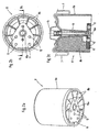
Fig. 1 eine Prinzipskizze einer Luftfederachse in teilweise eingefederter Lage; -
Fig. 2a eine perspektivische Ansicht eines Tauchkolbens; -
Fig. 2b eine Ansicht von unten des Tauchkolbens gemäßFig. 2a und -
Fig. 2c einen Schnitt entlang der Schnittline llc-llc gemäßFig. 2b . - Bei der in
Fig. 1 dargestellten Luftfederachse ist zwischen einem Teil eines Fahrzeugrahmens 1 und einem über eine Konsole 2 schwenkbar angelenkten Längslenker 3 für einen Achskörper 4 eine Luftfeder 5 eingebaut. - Die Luftfeder 5 besteht im Prinzip aus einem am Fahrzeugrahmen 1 befestigten Deckel 6, einem Rollbalg 7 und einem am Längslenker festgelegten Tauchkolben 8. Deckelseitig ist der Rollbalg 7 beispielsweise über einen (nicht dargestellten) Sprengring lösbar am Deckel 6 befestigt. Der Tauchkolben 8 mit seiner als Abrollfläche für den Rollbalg 7 dienenden zylindrischen Mantelfläche 8a ist über Befestigungsmittel 9 am rückwärtigen Ende des Längslenkers 3 befestigt.
- Der Aufbau einer Ausführungsform des Tauchkolbens 8 ist in den Abbildungen
Fig. 2a bis 2c dargestellt. Hierbei ist der Tauchkolben 8 als Spritzgußteil ausgebildet. Wie insbesondere aus den AbbildungenFig. 2a und 2b ersichtlich, weist der Tauchkolben 8 eine dünnwandige, kreisringförmige Mantelfläche 8a auf, von der aus sich eine Vielzahl von Stegen 8b zur Mitte des Tauchkolbens 8 hin erstrecken. Zur Aufnahme der Gewichtskräfte bei entlüfteter Luftfeder 5 ist in das Tauchkolbenprofil ein zentraler Stützkörper 10 einsetzbar, wie dies insbesondere ausFig. 2c ersichtlich ist. Die Verwendung dieses Stützkörpers 10 vermeidet, daß die Gewichtskräfte des Fahrzeugrahmens 1 bei entlüfteter Luftfeder 5 auf den dünnwandig ausgebildeten Tauchkolben 8 wirken. - Zur Aufnahme der Befestigungsmittel 9 zum Festlegen des Tauchkolbens 8 am Längslenker 3 ist in das längslenkerseitige Ende des Tauchkolbens 8 eine Halteplatte 11 eingesetzt bzw. eingearbeitet, die Gewindebohrungen 12 zur Aufnahme der als Schrauben ausgebildeten Befestigungsmittel 9 aufweist. Tauchkolbenseitig ist der Rollbalg 7 über einen einvulkanisierten Deckel 13 verschlossen, der darüber hinaus zum Festlegen des Rollbalgs 7 am-Tauchkolben 8 dient. Die Halteplatte 11 und der Deckel 13 sind über den als Gewindestange ausgebildeten Stützkörper 10 miteinander und somit auch mit dem Tauchkolben 8 verbunden. Um eine ebene Auflagefläche auf dem Längslenker 3 zu erhalten, ist ein Kopf 10a des Stützkörpers 10 im fertigmontierten Zustand bündig in der Halteplatte 11 versenkt. Zum Festlegen des Tauchkolbens 8 in verschiedenen Stellungen auf dem Längslenker 3 ist die Halteplatte 11 mit einer Mehrzahl von Gewindebohrungen 12 versehen.
- Der dargestellte Tauchkolben zeichnet sich dadurch aus, daß dieser direkt, d.h. ohne Zwischenschaltung der aus dem Stand der Technik bekannten Abschlußplatte auf dem rückwärtigen Ende des Längslenkers 3 festlegbar ist. Die nach unten offenen Tauchkolbenprofile weisen darüber hinaus den Vorteil auf, daß aufgrund der fehlenden Abschlußplatte ein ständiger Luftaustausch im Tauchkolbenprofil stattfinden kann, so daß sich keine korrosionsfördernde Atmosphäre im Inneren des Tauchkolbens 8 bilden kann.
Claims (3)
- Luftfeder für Luftfederachsen mit einem fahrestellfesten Decken (6) und einem auf einem rückwärtigen Ende eines Längslenkers (3) festgelegten Tauchkolben (8) sowie einem zwischen Deckel (6) und Tauchkolben (8) angeordneten Rollbalg (7), wobei der aus Kunststoffmaterial, vorzugsweise glasfaserverstärktem Kunststoffmaterial, bestehende Tauchkolben (8) nach unten offen ausgebildet auf dem Längslenker festlegbar ist und eine Mantelfläche (8a) aufweist, von der aus sich Stege (8b) im wesentlichen radial zur Mitte des Tauchkolbens (8) hin erstrecken, wobei längslenkerseitig in den Tauchkolben eine Halteplatte (11) zur Aufnahme von Befestigungsmitteln (9) zum Festlegen des Tauchkolbens (8) am Längslenker (3) eingesetzt bzw. eingearbeitet ist,
dadurch gekennzeichnet,
daß der Rollbalg (7) durch einen auf dem rollbalgseitigen Ende des Tauchkolbens (8) angeordneten Deckel (13) am Tauchkolben (8) festlegbar ist, daß zur Aufnahme der Gewichtskräfte bei entlüfteter Luftfeder ein zentraler Stützkörper (10) in das Tauchkolbenprofil eingesetzt ist, der Deckel (13) und Halteplatte (11) miteinander verbindet, und daß der Tauchkolben (8) direkt auf dem Längslenker (3) derart festlegbar ist, daß die Unterseite der Halteplatte (11) und die dem Längslenker zugewandten Stirnflächen der Mantelfläche (8a) und der Stege (8b) eine Ebene bilden. - Luftfeder nach Anspruch 1, dadurch gekennzeichnet, daß der Tauchkolben (8) als Strangpreßprofil ausgebildet ist.
- Luftfeder nach Anspruch 1, dadurch gekennzeichnet, daß der Tauchkolben (8) als Gußteil, vorzugsweise Spritzgußteil ausgebildet ist.
Applications Claiming Priority (2)
| Application Number | Priority Date | Filing Date | Title |
|---|---|---|---|
| DE19710849 | 1997-03-15 | ||
| DE19710849A DE19710849B4 (de) | 1997-03-15 | 1997-03-15 | Luftfeder für Luftfederachsen |
Publications (3)
| Publication Number | Publication Date |
|---|---|
| EP0864453A1 EP0864453A1 (de) | 1998-09-16 |
| EP0864453B1 EP0864453B1 (de) | 2002-01-09 |
| EP0864453B2 true EP0864453B2 (de) | 2008-08-20 |
Family
ID=7823527
Family Applications (1)
| Application Number | Title | Priority Date | Filing Date |
|---|---|---|---|
| EP98104218A Expired - Lifetime EP0864453B2 (de) | 1997-03-15 | 1998-03-10 | Luftfeder für Luftfederachsen |
Country Status (4)
| Country | Link |
|---|---|
| US (1) | US6024343A (de) |
| EP (1) | EP0864453B2 (de) |
| DE (3) | DE19710849B4 (de) |
| ES (1) | ES2170975T5 (de) |
Families Citing this family (26)
| Publication number | Priority date | Publication date | Assignee | Title |
|---|---|---|---|---|
| US6527259B1 (en) | 1999-07-07 | 2003-03-04 | Phoenix Ag | Pneumatic spring system |
| WO2001042678A1 (de) * | 1999-12-09 | 2001-06-14 | Phoenix Ag | Luftfederanordnung |
| DE10018238C1 (de) * | 2000-04-12 | 2001-12-20 | Vaw Alutubes Gmbh | Abrollkolben für Luftfedersysteme |
| US6945548B2 (en) * | 2001-02-26 | 2005-09-20 | Hendrickson Usa, L.L.C. | Air spring and air spring mounting assembly |
| DE10149057B4 (de) | 2001-10-05 | 2021-05-12 | Bpw Bergische Achsen Kg | Tauchkolben für eine Luftfeder |
| US7500659B2 (en) * | 2005-04-07 | 2009-03-10 | Bfs Diversified Products, Llc | Air spring assembly and method |
| US7530554B2 (en) | 2006-03-08 | 2009-05-12 | Bfs Diversified Products, Llc | Fluid spring assembly and method |
| DE102006032383B3 (de) * | 2006-07-13 | 2007-11-22 | Hermann Peters Gmbh & Co. | Leichtbau-Tauchkolben |
| EP2066916B1 (de) * | 2006-09-14 | 2012-04-25 | ContiTech Luftfedersysteme GmbH | Kunststoffdeckel für nutzfahrzeugluftfedern mit eingepasstem puffer |
| US8061691B2 (en) * | 2007-02-05 | 2011-11-22 | Bfs Diversified Products, Llc | Piston and gas spring assembly including same |
| DE102007035640A1 (de) * | 2007-07-27 | 2009-01-29 | Lkh-Kunststoffwerk Gmbh & Co. Kg | Tauchkolben |
| US20090200717A1 (en) * | 2008-02-08 | 2009-08-13 | Veyance Technologies, Inc. | Air spring piston |
| US8231113B2 (en) * | 2008-06-05 | 2012-07-31 | Firestone Industrial Products Company, Llc | Gas spring assembly and spacer |
| US8613430B2 (en) * | 2009-04-01 | 2013-12-24 | Firestone Industrial Products Company, Llc | Gas spring assembly and suspension system including same |
| US8864113B2 (en) | 2009-10-14 | 2014-10-21 | Firestone Industrial Products Company, Llc | End member, gas spring assembly and method |
| TR201000543A2 (tr) * | 2010-01-26 | 2011-01-21 | Aktaş Hava Süspansi̇yon Si̇stemleri̇ Sanayi̇ Ve Ti̇caret A.Ş. | Havalı süspansiyon tertibatlarında kullanılan, termoplastik malzeme esaslı takozlu alt tas |
| DE102010000620A1 (de) | 2010-03-03 | 2011-09-08 | Bpw Bergische Achsen Kg | Achslenker für eine luftgefederte Fahrzeugachse |
| DE102012201745B4 (de) * | 2012-02-07 | 2015-08-20 | Saf-Holland Gmbh | Luftfederbefestigung |
| US10005333B2 (en) * | 2013-05-28 | 2018-06-26 | Firestone Industrial Products Company, Llc | End member assemblies and travel-restraint assemblies as well as gas spring assemblies including same |
| DE102014108701A1 (de) * | 2014-06-20 | 2015-12-24 | Radkersburger Metallwarenfabrik Gmbh | Abrollkolben für eine Luftfeder |
| EP3227132B1 (de) * | 2014-12-04 | 2021-06-02 | Firestone Industrial Products Company, LLC | Kolbendesign mit erhöhter seitlicher festigkeit |
| DE102015108519B3 (de) * | 2015-05-29 | 2016-07-28 | Saf-Holland Gmbh | Stützeinheit |
| US10618366B2 (en) * | 2016-07-08 | 2020-04-14 | Continental Automotive Systems, Inc. | Vehicle air strut with twist lock closure cover |
| DE102019105705A1 (de) * | 2019-03-06 | 2020-09-10 | Bayerische Motoren Werke Aktiengesellschaft | Federbein-Stützlager eines Fahrzeugs |
| USD913081S1 (en) | 2019-05-29 | 2021-03-16 | The Boeing Company | Structural spacer member |
| US11059586B2 (en) * | 2019-05-29 | 2021-07-13 | The Boeing Company | Structural spacer members |
Citations (5)
| Publication number | Priority date | Publication date | Assignee | Title |
|---|---|---|---|---|
| US3897941A (en) † | 1974-03-28 | 1975-08-05 | Goodyear Tire & Rubber | Reinforced fluid spring |
| US4798369A (en) † | 1987-11-03 | 1989-01-17 | The Firestone Tire & Rubber Company | Ultrasonic air spring system |
| US4923210A (en) † | 1989-03-28 | 1990-05-08 | Heider Merle J | Suspension and leveling system for a vehicle |
| US4946144A (en) † | 1989-03-30 | 1990-08-07 | Bridgestone/Firestone, Inc. | External clamping band for air spring |
| DE3907462A1 (de) † | 1989-03-08 | 1990-09-13 | Continental Ag | Rollbalg-luftfeder |
Family Cites Families (10)
| Publication number | Priority date | Publication date | Assignee | Title |
|---|---|---|---|---|
| AT277781B (de) * | 1964-02-20 | 1970-01-12 | Neway Equipment Co | Achsführung für eine luftgefederte Starrachse eines Kraftfahrzeuges |
| DE3147231C1 (de) * | 1981-11-28 | 1983-03-31 | Bergische Achsenfabrik Fr. Kotz & Söhne, 5276 Wiehl | Luftfeder |
| US4506910A (en) * | 1982-09-21 | 1985-03-26 | Granning Suspensions, Inc. | Automotive vehicle suspension |
| US4650166A (en) * | 1984-12-14 | 1987-03-17 | The Goodyear Tire & Rubber Company | Two piece piston for airsprings |
| IT1205188B (it) * | 1987-06-26 | 1989-03-15 | Pirelli | Miglioramenti nelle molle ad aria |
| DE3824542A1 (de) * | 1988-07-20 | 1990-01-25 | Sauer Achsenfab | Tauchkolbenanordnung |
| DE4008187A1 (de) * | 1990-03-15 | 1991-09-19 | Continental Ag | Abrollkolben fuer den rollbalg einer rollbalg-luftfeder |
| DE4213676C2 (de) * | 1992-04-25 | 1996-02-22 | Continental Ag | Luftfeder für Fahrzeuge mit einem elastomeren Rollbalg und einem Abrollkolben |
| US5382006A (en) * | 1993-09-29 | 1995-01-17 | The Goodyear Tire & Rubber Company | Airspring piston and airspring assembly |
| US5535994A (en) * | 1993-11-30 | 1996-07-16 | The Goodyear Tire & Rubber Company | Composite air spring piston |
-
1997
- 1997-03-15 DE DE19710849A patent/DE19710849B4/de not_active Expired - Lifetime
- 1997-03-15 DE DE19758726A patent/DE19758726B4/de not_active Expired - Lifetime
-
1998
- 1998-03-10 ES ES98104218T patent/ES2170975T5/es not_active Expired - Lifetime
- 1998-03-10 EP EP98104218A patent/EP0864453B2/de not_active Expired - Lifetime
- 1998-03-10 DE DE59802595T patent/DE59802595D1/de not_active Expired - Lifetime
- 1998-03-13 US US09/039,108 patent/US6024343A/en not_active Expired - Fee Related
Patent Citations (5)
| Publication number | Priority date | Publication date | Assignee | Title |
|---|---|---|---|---|
| US3897941A (en) † | 1974-03-28 | 1975-08-05 | Goodyear Tire & Rubber | Reinforced fluid spring |
| US4798369A (en) † | 1987-11-03 | 1989-01-17 | The Firestone Tire & Rubber Company | Ultrasonic air spring system |
| DE3907462A1 (de) † | 1989-03-08 | 1990-09-13 | Continental Ag | Rollbalg-luftfeder |
| US4923210A (en) † | 1989-03-28 | 1990-05-08 | Heider Merle J | Suspension and leveling system for a vehicle |
| US4946144A (en) † | 1989-03-30 | 1990-08-07 | Bridgestone/Firestone, Inc. | External clamping band for air spring |
Also Published As
| Publication number | Publication date |
|---|---|
| DE19710849B4 (de) | 2009-04-09 |
| DE19710849A1 (de) | 1998-09-24 |
| EP0864453B1 (de) | 2002-01-09 |
| DE19758726B4 (de) | 2006-07-20 |
| ES2170975T3 (es) | 2002-08-16 |
| US6024343A (en) | 2000-02-15 |
| DE59802595D1 (de) | 2002-02-14 |
| ES2170975T5 (es) | 2009-02-01 |
| EP0864453A1 (de) | 1998-09-16 |
Similar Documents
| Publication | Publication Date | Title |
|---|---|---|
| EP0864453B1 (de) | Luftfeder für Luftfederachsen | |
| EP1300264B1 (de) | Luftfeder für eine Fahrzeugachsaufhängung | |
| EP1504983B1 (de) | Hilfsrahmen für Fahrzeuge | |
| EP2982528B1 (de) | Achsaufhängung für gelenkte starrachsen in fahrzeugen, insbesondere nutzfahrzeuge | |
| EP3441523A1 (de) | Tragschiene für eine translativ verfahrbare roboterplattform | |
| EP0351678A2 (de) | Tauchkolbenanordnung | |
| DE2127258C3 (de) | Anordnung einer Stoßstange an einem Fahrzeug, insbesondere an einem Kraftfahrzeug | |
| DE102011054330A1 (de) | Abrollkolben für einen Luftfederbalg | |
| WO2022194509A1 (de) | Speichergehäuse für einen elektrischen energiespeicher eines kraftwagens | |
| EP0352541A1 (de) | Federnde Achsaufhängung für Kraftfahrzeuge, insbesondere Nutzfahrzeuge | |
| EP1231129A2 (de) | Lastfahrzeug | |
| DE60010667T2 (de) | Verfahren und vorrichtung für die lagerung eines fahrerhauses in bezug auf das fahrgestell | |
| DE9207011U1 (de) | Domstrebe für Kraftfahrzeuge | |
| DE19911021B4 (de) | Führungslenker für eine Kraftfahrzeugradaufhängung | |
| DE3017733C2 (de) | ||
| DE19606536C1 (de) | Kastenaufbau für ein Nutzfahrzeug, insbesondere ein Einsatzfahrzeug, wie ein Feuerwehrfahrzeug | |
| EP3250402B1 (de) | Blattfeder-anordnung im fahrwerk eines fahrzeugs | |
| DE894053C (de) | Unabhaengige Radaufhaengung fuer Kraftfahrzeuge | |
| EP4126572B1 (de) | Verbindungsanordnung zwischen einer luftfeder und einem luftfederträger | |
| DE29724626U1 (de) | Luftfeder für Luftfederachsen | |
| DE102015117757B4 (de) | Lenkerende | |
| EP1036677A2 (de) | Radaufhängung für ein Kraftfahrzeug | |
| EP0940325A1 (de) | Fahrgestell eines schweren Nutzfahrzeuges | |
| EP0940324A1 (de) | Fahrgestell eines schweren Nutzfahrzeuges | |
| DE19730856C2 (de) | Verbindung der Stirnseiten von zwei hohlen Vierkantprofilen |
Legal Events
| Date | Code | Title | Description |
|---|---|---|---|
| PUAI | Public reference made under article 153(3) epc to a published international application that has entered the european phase |
Free format text: ORIGINAL CODE: 0009012 |
|
| AK | Designated contracting states |
Kind code of ref document: A1 Designated state(s): DE ES FR GB IT NL |
|
| AX | Request for extension of the european patent |
Free format text: AL;LT;LV;MK;RO;SI |
|
| 17P | Request for examination filed |
Effective date: 19990304 |
|
| AKX | Designation fees paid |
Free format text: DE ES FR GB IT NL |
|
| RBV | Designated contracting states (corrected) |
Designated state(s): DE ES FR GB IT NL |
|
| 17Q | First examination report despatched |
Effective date: 20001122 |
|
| GRAG | Despatch of communication of intention to grant |
Free format text: ORIGINAL CODE: EPIDOS AGRA |
|
| GRAG | Despatch of communication of intention to grant |
Free format text: ORIGINAL CODE: EPIDOS AGRA |
|
| GRAH | Despatch of communication of intention to grant a patent |
Free format text: ORIGINAL CODE: EPIDOS IGRA |
|
| GRAH | Despatch of communication of intention to grant a patent |
Free format text: ORIGINAL CODE: EPIDOS IGRA |
|
| GRAA | (expected) grant |
Free format text: ORIGINAL CODE: 0009210 |
|
| REG | Reference to a national code |
Ref country code: GB Ref legal event code: IF02 |
|
| AK | Designated contracting states |
Kind code of ref document: B1 Designated state(s): DE ES FR GB IT NL |
|
| REF | Corresponds to: |
Ref document number: 59802595 Country of ref document: DE Date of ref document: 20020214 |
|
| GBT | Gb: translation of ep patent filed (gb section 77(6)(a)/1977) |
Effective date: 20020405 |
|
| TPAD | Observations filed by third parties |
Free format text: ORIGINAL CODE: EPIDOS TIPA |
|
| REG | Reference to a national code |
Ref country code: ES Ref legal event code: FG2A Ref document number: 2170975 Country of ref document: ES Kind code of ref document: T3 |
|
| PLBQ | Unpublished change to opponent data |
Free format text: ORIGINAL CODE: EPIDOS OPPO |
|
| PLBI | Opposition filed |
Free format text: ORIGINAL CODE: 0009260 |
|
| PLBI | Opposition filed |
Free format text: ORIGINAL CODE: 0009260 |
|
| PLBQ | Unpublished change to opponent data |
Free format text: ORIGINAL CODE: EPIDOS OPPO |
|
| 26 | Opposition filed |
Opponent name: HERMANN PETERS GMBH & CO. Effective date: 20020913 |
|
| PLBF | Reply of patent proprietor to notice(s) of opposition |
Free format text: ORIGINAL CODE: EPIDOS OBSO |
|
| 26 | Opposition filed |
Opponent name: LFT GERMANY GMBH Effective date: 20021009 Opponent name: HERMANN PETERS GMBH & CO. Effective date: 20020913 |
|
| NLR1 | Nl: opposition has been filed with the epo |
Opponent name: HERMANN PETERS GMBH & CO. |
|
| NLR1 | Nl: opposition has been filed with the epo |
Opponent name: LFT GERMANY GMBH Opponent name: HERMANN PETERS GMBH & CO. |
|
| PLBF | Reply of patent proprietor to notice(s) of opposition |
Free format text: ORIGINAL CODE: EPIDOS OBSO |
|
| APAH | Appeal reference modified |
Free format text: ORIGINAL CODE: EPIDOSCREFNO |
|
| APBP | Date of receipt of notice of appeal recorded |
Free format text: ORIGINAL CODE: EPIDOSNNOA2O |
|
| APBQ | Date of receipt of statement of grounds of appeal recorded |
Free format text: ORIGINAL CODE: EPIDOSNNOA3O |
|
| PLAB | Opposition data, opponent's data or that of the opponent's representative modified |
Free format text: ORIGINAL CODE: 0009299OPPO |
|
| R26 | Opposition filed (corrected) |
Opponent name: LFT GERMANY LUFTFEDERTECHNIK GMBH Effective date: 20021009 Opponent name: HERMANN PETERS GMBH & CO. Effective date: 20020913 |
|
| NLR1 | Nl: opposition has been filed with the epo |
Opponent name: LFT GERMANY LUFTFEDERTECHNIK GMBH Opponent name: HERMANN PETERS GMBH & CO. |
|
| APBU | Appeal procedure closed |
Free format text: ORIGINAL CODE: EPIDOSNNOA9O |
|
| PUAH | Patent maintained in amended form |
Free format text: ORIGINAL CODE: 0009272 |
|
| STAA | Information on the status of an ep patent application or granted ep patent |
Free format text: STATUS: PATENT MAINTAINED AS AMENDED |
|
| 27A | Patent maintained in amended form |
Effective date: 20080820 |
|
| AK | Designated contracting states |
Kind code of ref document: B2 Designated state(s): DE ES FR GB IT NL |
|
| NLR2 | Nl: decision of opposition |
Effective date: 20080820 |
|
| REG | Reference to a national code |
Ref country code: ES Ref legal event code: DC2A Date of ref document: 20081022 Kind code of ref document: T5 |
|
| REG | Reference to a national code |
Ref country code: DE Ref legal event code: R082 Ref document number: 59802595 Country of ref document: DE Representative=s name: BUNGARTZ CHRISTOPHERSEN PARTNERSCHAFT MBB PATE, DE |
|
| REG | Reference to a national code |
Ref country code: FR Ref legal event code: PLFP Year of fee payment: 19 |
|
| REG | Reference to a national code |
Ref country code: FR Ref legal event code: PLFP Year of fee payment: 20 |
|
| PGFP | Annual fee paid to national office [announced via postgrant information from national office to epo] |
Ref country code: FR Payment date: 20170323 Year of fee payment: 20 Ref country code: NL Payment date: 20170323 Year of fee payment: 20 |
|
| PGFP | Annual fee paid to national office [announced via postgrant information from national office to epo] |
Ref country code: GB Payment date: 20170327 Year of fee payment: 20 |
|
| PGFP | Annual fee paid to national office [announced via postgrant information from national office to epo] |
Ref country code: DE Payment date: 20170404 Year of fee payment: 20 |
|
| PGFP | Annual fee paid to national office [announced via postgrant information from national office to epo] |
Ref country code: ES Payment date: 20170323 Year of fee payment: 20 |
|
| PGFP | Annual fee paid to national office [announced via postgrant information from national office to epo] |
Ref country code: IT Payment date: 20170323 Year of fee payment: 20 |
|
| REG | Reference to a national code |
Ref country code: DE Ref legal event code: R071 Ref document number: 59802595 Country of ref document: DE |
|
| REG | Reference to a national code |
Ref country code: NL Ref legal event code: MK Effective date: 20180309 |
|
| REG | Reference to a national code |
Ref country code: GB Ref legal event code: PE20 Expiry date: 20180309 |
|
| PG25 | Lapsed in a contracting state [announced via postgrant information from national office to epo] |
Ref country code: GB Free format text: LAPSE BECAUSE OF EXPIRATION OF PROTECTION Effective date: 20180309 |
|
| REG | Reference to a national code |
Ref country code: ES Ref legal event code: FD2A Effective date: 20200904 |
|
| PG25 | Lapsed in a contracting state [announced via postgrant information from national office to epo] |
Ref country code: ES Free format text: LAPSE BECAUSE OF EXPIRATION OF PROTECTION Effective date: 20180311 |