EP0864335B1 - Spritzenschutz - Google Patents
Spritzenschutz Download PDFInfo
- Publication number
- EP0864335B1 EP0864335B1 EP98301704A EP98301704A EP0864335B1 EP 0864335 B1 EP0864335 B1 EP 0864335B1 EP 98301704 A EP98301704 A EP 98301704A EP 98301704 A EP98301704 A EP 98301704A EP 0864335 B1 EP0864335 B1 EP 0864335B1
- Authority
- EP
- European Patent Office
- Prior art keywords
- shield
- guard
- cartridge
- detents
- proximal
- Prior art date
- Legal status (The legal status is an assumption and is not a legal conclusion. Google has not performed a legal analysis and makes no representation as to the accuracy of the status listed.)
- Expired - Lifetime
Links
Images


Classifications
-
- A—HUMAN NECESSITIES
- A61—MEDICAL OR VETERINARY SCIENCE; HYGIENE
- A61M—DEVICES FOR INTRODUCING MEDIA INTO, OR ONTO, THE BODY; DEVICES FOR TRANSDUCING BODY MEDIA OR FOR TAKING MEDIA FROM THE BODY; DEVICES FOR PRODUCING OR ENDING SLEEP OR STUPOR
- A61M5/00—Devices for bringing media into the body in a subcutaneous, intra-vascular or intramuscular way; Accessories therefor, e.g. filling or cleaning devices, arm-rests
- A61M5/178—Syringes
- A61M5/31—Details
- A61M5/32—Needles; Details of needles pertaining to their connection with syringe or hub; Accessories for bringing the needle into, or holding the needle on, the body; Devices for protection of needles
- A61M5/3205—Apparatus for removing or disposing of used needles or syringes, e.g. containers; Means for protection against accidental injuries from used needles
- A61M5/321—Means for protection against accidental injuries by used needles
- A61M5/3243—Means for protection against accidental injuries by used needles being axially-extensible, e.g. protective sleeves coaxially slidable on the syringe barrel
- A61M5/3271—Means for protection against accidental injuries by used needles being axially-extensible, e.g. protective sleeves coaxially slidable on the syringe barrel with guiding tracks for controlled sliding of needle protective sleeve from needle exposing to needle covering position
-
- A—HUMAN NECESSITIES
- A61—MEDICAL OR VETERINARY SCIENCE; HYGIENE
- A61M—DEVICES FOR INTRODUCING MEDIA INTO, OR ONTO, THE BODY; DEVICES FOR TRANSDUCING BODY MEDIA OR FOR TAKING MEDIA FROM THE BODY; DEVICES FOR PRODUCING OR ENDING SLEEP OR STUPOR
- A61M5/00—Devices for bringing media into the body in a subcutaneous, intra-vascular or intramuscular way; Accessories therefor, e.g. filling or cleaning devices, arm-rests
- A61M5/178—Syringes
- A61M5/31—Details
- A61M5/3129—Syringe barrels
- A61M5/3137—Specially designed finger grip means, e.g. for easy manipulation of the syringe rod
- A61M2005/3139—Finger grips not integrally formed with the syringe barrel, e.g. using adapter with finger grips
-
- A—HUMAN NECESSITIES
- A61—MEDICAL OR VETERINARY SCIENCE; HYGIENE
- A61M—DEVICES FOR INTRODUCING MEDIA INTO, OR ONTO, THE BODY; DEVICES FOR TRANSDUCING BODY MEDIA OR FOR TAKING MEDIA FROM THE BODY; DEVICES FOR PRODUCING OR ENDING SLEEP OR STUPOR
- A61M5/00—Devices for bringing media into the body in a subcutaneous, intra-vascular or intramuscular way; Accessories therefor, e.g. filling or cleaning devices, arm-rests
- A61M5/178—Syringes
- A61M5/31—Details
- A61M5/315—Pistons; Piston-rods; Guiding, blocking or restricting the movement of the rod or piston; Appliances on the rod for facilitating dosing ; Dosing mechanisms
- A61M5/31501—Means for blocking or restricting the movement of the rod or piston
- A61M2005/31508—Means for blocking or restricting the movement of the rod or piston provided on the piston-rod
-
- A—HUMAN NECESSITIES
- A61—MEDICAL OR VETERINARY SCIENCE; HYGIENE
- A61M—DEVICES FOR INTRODUCING MEDIA INTO, OR ONTO, THE BODY; DEVICES FOR TRANSDUCING BODY MEDIA OR FOR TAKING MEDIA FROM THE BODY; DEVICES FOR PRODUCING OR ENDING SLEEP OR STUPOR
- A61M5/00—Devices for bringing media into the body in a subcutaneous, intra-vascular or intramuscular way; Accessories therefor, e.g. filling or cleaning devices, arm-rests
- A61M5/178—Syringes
- A61M5/31—Details
- A61M5/32—Needles; Details of needles pertaining to their connection with syringe or hub; Accessories for bringing the needle into, or holding the needle on, the body; Devices for protection of needles
- A61M5/3205—Apparatus for removing or disposing of used needles or syringes, e.g. containers; Means for protection against accidental injuries from used needles
- A61M5/321—Means for protection against accidental injuries by used needles
- A61M5/3243—Means for protection against accidental injuries by used needles being axially-extensible, e.g. protective sleeves coaxially slidable on the syringe barrel
- A61M5/3245—Constructional features thereof, e.g. to improve manipulation or functioning
- A61M2005/3247—Means to impede repositioning of protection sleeve from needle covering to needle uncovering position
-
- A—HUMAN NECESSITIES
- A61—MEDICAL OR VETERINARY SCIENCE; HYGIENE
- A61M—DEVICES FOR INTRODUCING MEDIA INTO, OR ONTO, THE BODY; DEVICES FOR TRANSDUCING BODY MEDIA OR FOR TAKING MEDIA FROM THE BODY; DEVICES FOR PRODUCING OR ENDING SLEEP OR STUPOR
- A61M5/00—Devices for bringing media into the body in a subcutaneous, intra-vascular or intramuscular way; Accessories therefor, e.g. filling or cleaning devices, arm-rests
- A61M5/178—Syringes
- A61M5/31—Details
- A61M5/3129—Syringe barrels
-
- A—HUMAN NECESSITIES
- A61—MEDICAL OR VETERINARY SCIENCE; HYGIENE
- A61M—DEVICES FOR INTRODUCING MEDIA INTO, OR ONTO, THE BODY; DEVICES FOR TRANSDUCING BODY MEDIA OR FOR TAKING MEDIA FROM THE BODY; DEVICES FOR PRODUCING OR ENDING SLEEP OR STUPOR
- A61M5/00—Devices for bringing media into the body in a subcutaneous, intra-vascular or intramuscular way; Accessories therefor, e.g. filling or cleaning devices, arm-rests
- A61M5/178—Syringes
- A61M5/31—Details
- A61M5/32—Needles; Details of needles pertaining to their connection with syringe or hub; Accessories for bringing the needle into, or holding the needle on, the body; Devices for protection of needles
- A61M5/3202—Devices for protection of the needle before use, e.g. caps
Definitions
- the present invention relates generally to syringes, and more particularly to an improved syringe guard for a unit dose ampule or syringe and including a shield for covering the needle thereof after medication is dispensed from the syringe.
- Medication is often dispensed using a unit dose cartridge, such as an ampule or syringe, and a syringe holder or adapter.
- the cartridge is typically a barrel having a needle at one end and a piston at the other end.
- the cartridge may include a rubber stopper instead of a needle, or may include a plunger assembly attached to the piston.
- the syringe adapter is typically a hollow body adapted to hold the cartridge, including a plunger to engage and move the piston in the cartridge.
- U.S. Patent No. 5,569,211 discloses a syringe that allows the needle of the.syringe to be withdrawn into the barrel of the syringe after medication is dispensed from it.
- This device is a specially designed substitute for a conventional syringe, and cannot be used to hold commercially available unit dose cartridges.
- U.S. Patent No. 5,522,812 discloses a complicated syringe shield device for holding a conventional ampule not having its own needle.
- the device has a number of complicated parts, including a cylindrical body, a double needle assembly, a cylindrical shield, a special collar piece allowing the shield to be drawn over the needle and locked, and a plunger assembly, resulting in a device that is potentially difficult and expensive to manufacture.
- the device also requires two hands to operate, one to hold the body, and one to rotate the shield into the locked position, causing inconvenience to the medical professional using the device.
- GB 2283425 discloses a protection sheath for a syringe possessing a needle.
- the sheath comprises a tubular body that can slide over the barrel of the syringe from an inoperative position to an extended locking position where it shields the needle.
- the protective sheath comprises inner and outer tubular members. The inner tubular member is fixed by clips to the barrel of the syringe and the outer tubular member is slidably mounted to the inner member so that it can be moved between a retracted position in which the needle is exposed and a locked extended position in which it shields the needle.
- WO 95/04565 discloses self-shielding aspirating syringe which comprises a body including a cavity for receiving a medical carpule and a needle for penetrating the carpule and for injecting medication into a patient.
- the syringe is provided with protector case which is adapted to slidably fit onto the body of the syringe and a first open end through which a needle extends and a second end provided with co-operating detents for facilitating placement of the case with respect to the body for uncovering and covering the exposed end of the needle.
- unit dose cartridges are often made from glass, particularly for holding certain vaccines or biotech drugs where concern about micro-organisms or other contaminants is most critical. Glass cartridges are very fragile and often break during transportation or use. Some existing adapters may not adequately protect the cartridge contained therein from such risks. Others provide greater protection for the cartridge, but may obstruct the professional's view of the cartridge when the device is being used, hampering monitoring of the medication being delivered.
- the present invention is directed to a guard or adapter for a medical cartridge, such as a unit dose ampule or syringe, that may be used to inject medication or other drugs into a patient.
- the guard comprises two parts, namely a housing or body for receiving and holding the cartridge, and a protective case or shield slidably attached to the body.
- the various parts are generally molded from a suitable plastic, preferably k-resin or polycarbonate, having a clear or opaque finish, which may be colored, such as a latex color or a flesh tone.
- the body generally may comprise two elongate rails or similar structures defining a substantially rectangular shape, having a cavity therein adapted to receive a medical cartridge.
- the body has an open proximal end communicating with the cavity, a distal end with an opening through it, and possibly a collar molded to the distal end.
- the protective case or shield is preferably a tubular member adapted to slidably fit on the body, having open proximal and distal ends.
- One or more elongate windows may be formed in the shield, allowing observation of the cartridge when held within the body.
- One or more windows preferably the same windows used for viewing the cartridge, may also cooperate with a stop tab or tabs molded on the body, thereby limiting the relative sliding relationship of the shield and the body.
- the shield may include a set of detents, preferably comprising a pair of detent arms and protruding detents molded into the proximal end of the shield. The detents may cooperate with one or more sets of detent pockets molded into the body to lock the shield in relation to the body.
- detents may be provided on the body with detent pockets on the shield.
- the shield may generally be provided pre-assembled on the body, preferably by inserting the body into the shield until the stop tabs on the body communicate with the elongate windows on the shield. The shield may then slide in relation to the body between a proximal or unguarded position and a distal or guarded position, defined by the length of the windows on the shield.
- the guard is usually provided with the shield in the proximal or unguarded position, wherein the stop tabs abut the distal edges of the windows. In the unguarded position, the detents on the shield preferably engage a set of proximal detent pockets on the body, holding the shield in relation to the body.
- the shield is moved distally until it reaches the guarded position.
- the stop tabs on the body abut the proximal edges of the windows, preventing further distal movement.
- the detents on the shield leave the proximal detent pockets, preferably because of sloping edges on the proximal detent pockets, and slide along the body until they enter a set of distal detent pockets when the shield reaches the guarded position.
- the distal detent pockets preferably have blunt edges, which prevent the shield from being returned proximally, and thereby substantially lock the shield in the guarded position for disposal.
- the guard comprises only two parts, namely a body and a shield, which are pre-assembled in the unguarded position ready to receive a cartridge.
- the body may include a finger grip molded onto its proximal end, preferably defining a "T" shape, having locking detents formed on the finger grip.
- a cartridge preferably and typically a conventional unit dose syringe including a needle and needle cover on its distal end and a plunger on its proximal end, is inserted into the proximal end of the body until it is fully encapsulated within the cavity. Once fully inserted, the proximal end of the cartridge engages the locking detents on the finger grip, substantially permanently locking the cartridge into the guard. Once locked into the guard, the needle and its cover on the cartridge extend through the distal openings in the body and shield and beyond their distal ends.
- the shield is slid into the guarded position, generally using only one hand.
- the index and middle fingers are generally placed on the finger grip adjacent the shield, while the thumb directs the plunger on the cartridge.
- the thumb and ring finger are moved to the finger grip to hold the body.
- the index and middle fingers hold the sides of the shield and move it distally, thereby sliding the shield until it is locked in the guarded position.
- the present invention provides an improved medical cartridge guard, that may include as few as two parts, but generally has no more than four parts.
- the device may be used for a wide variety of conventional prepackaged medications or drugs, such as anesthesia or vaccines, for use within the medical and/or dental fields, where the cartridge is generally disposed of after a single use.
- the parts may be provided in standard configurations. For example, a single shield design may be provided that fits on a variety of bodies for receiving cartridges made by different manufacturers.
- the guard may be more easily mass produced, reducing manufacturing costs, and thereby providing a more competitively priced disposable syringe guard.
- the rectangular configuration of embodiments of the present device provides improved rigidity, thereby affording greater protection to the cartridge held in the guard.
- the cartridge may be fully encapsulated within the guard, the windows in the guard allow the medical or dental professional to effectively monitor the cartridge and the medication being delivered.
- the slidable shield and cooperating detents may allow the user to operate the guard using only one hand, thereby allowing their other hand to be free to perform other necessary tasks, such as restraining a young patient or providing improved access to the target region for the needle.
- the shield Once the shield is locked in the guarded position, the device may be disposed of safely if used properly, substantially eliminating concerns that the needle may become exposed and cause an accidental stick.
- a guard for a medical cartridge having a proximal and a distal end, and a lip on the proximal end and having its own needle extending from the distal end
- the guard comprising a rigid body having a cavity adapted to receive the cartridge axially therein through an open proximal end of the body, and having a distal end including an opening through which the needle may extend when the cartridge is received within the cavity, and a shield slidably attached to the body, and having open proximal and distal ends, the shield being slidable between an unguarded and a guarded position, thereby uncovering and covering, respectively, the needle on the cartridge
- the guard characterized by:
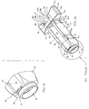
- FIG. 1 shows a first preferred embodiment of the present invention, namely a syringe guard 10 for holding a unit dose syringe 90.
- the guard 10 comprises two parts, namely a housing or body 20 for receiving and holding the cartridge or syringe 90, and a protective case or shield 60 slidably attached to the body 20.
- Both the body 20 and the shield 60 are generally molded from plastic, preferably k-resin or polycarbonate, and are preferably clear and substantially colorless. Alternatively they may be translucent or opaque, and may be colored, such as a latex color, or a flesh tone, such as off-white, brown, or black.
- the body 20 is an elongate member, preferably having a substantially rectangular cross-section, comprising two side rails 28, an open proximal end 22, and an open distal end 24.
- the rectangular shape is preferred as it provides superior rigidity, protecting the syringe therein from lateral forces that might otherwise damage it, particularly if the syringe is made of glass.
- the body 20 has a collar 32 on the distal end 24, and a finger grip 50 on the proximal end 22, both attached to or preferably integrally molded onto the body 20.
- the body 20 may comprise a substantially rectangular body having four side walls (not shown).
- the two side rails 28 generally have a "C" shape and define a cavity 26 in the body 20, the cavity 26 extending from the proximal end 22 to the distal end 24 of the body 20.
- the inside surface 30 of the rails 28 is preferably concave, conforming substantially to the outer diameter of a standard unit dose syringe.
- guide rails (not shown) or the like may be provided on the inside surface 30 to direct the cartridge 90 into the cavity 26 and hold it, thereby substantially preventing lateral movement which may damage the cartridge 90.
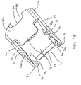
- the finger grip 50 generally comprises a pair of wing-like members 52 molded onto the proximal end 22 of the body 20, thereby generally defining a "T" shape.
- Each wing-like member 52 includes a distal surface or finger ledge 54, and an outer gripping surface 56 extending proximally from the outer edge 54a of the finger ledge 54.
- the outer gripping surface 56 may include a lip (not shown) protruding radially from its proximal end, if desired to improve the hold on the finger grip 50.
- Lateral surfaces 55 extend proximally from the finger ledges 54 between the gripping surfaces 56, thereby defining an open proximal end 51 communicating with the cavity 26 in the body 20.
- the lateral surfaces 55 of the finger grip 50 include a plurality of locking detents 58 partially defining an aperture or slot 57 for holding the cartridge (not shown in FIGS. 2A and 2B) inserted into the cavity 26, as will be described further below.
- the collar 32 extending from the distal end 24 preferably has a substantially annular shape, including an opening 34 extending therethrough adapted to allow the needle and needle cover on the cartridge (not shown) in the cavity 26 to extend beyond the body 20.
- the opening 34 preferably has a diameter smaller than the cavity 26, such that the distal end 24 substantially retains the cartridge inside the cavity 26, preventing distal movement.
- the distal end 24 may be tapered or otherwise partially obstructed, as long as it engages the distal end of the cartridge, preventing distal movement of the cartridge, and does not substantially interfere with the needle and cover extending beyond the distal end 24.
- the side rails 28 define two elongate openings or windows 36 extending longitudinally between the finger grip 50 and the distal end 24, allowing observation of the cartridge held in the body 20.
- an elongate opening or window may be integrally formed in one or more of the side walls, preferably in two walls on opposite sides of the body 20.
- the body 20 also includes one or more stop tabs 38 attached or molded directly to the body 20. Preferably, stop tabs 38 are molded onto the body 20 on two opposite sides of the distal end 24 of the body 20.
- the body 20 also includes one or more sets of detent pockets, preferably having a set of proximal detent pockets 40 adjacent the finger grip 50, and a set of distal detent pockets 42 at a more distal location on the body 20.
- the detent pockets lock the relative movement between the shield 60 and body 20, as is explained more fully below.
- the protective case or shield 60 is a tubular member adapted to slidably fit on the body 20, preferably having a substantially rectangular interior shape which conforms to the shape of the body 20.
- the shield 60 includes four side walls 61a, 61b, an open proximal end 62, and an open distal end 63.
- the shield 60 has a pair of detent arms 70 and a plurality of detents 71 attached to or preferably integrally molded directly into the side walls 61b. Assembly tabs 72 with sloping or ramped interior surfaces 73 are molded into and extend proximally from the side walls 61a.
- At least one wall 61a preferably the two opposite walls 61a, includes an elongate opening or window 64 therethrough.
- the window.64 allows observation of the cartridge in the body 20, and also provides a traveling slot for the stop tab 38 on the body 20.
- the window 64 has a proximal edge 66 and a distal edge 68 defined by the wall 61a which limit the relative movement of the shield 60 to the body 20, as will be explained more fully below.
- the window 64 may be divided by a cross-member (not shown) molded into the wall 61a which extends transversely across the window 64 if it is desired to further limit the movement of the shield 60.
- the side walls 61a, 61b may include wings, a ring or similar finger holds (not shown) extending radially from the shield 60 to ease movement of the shield 60 in relation to the body 20.
- the side walls 61b may provide a flat surface onto which a label may be applied or an embossed pattern may be molded, possibly including a name or a logo.
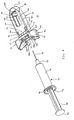
- the guard 10 is normally provided with the body 20 and shield 60 pre-assembled as shown.
- the distal end 24 of the body 20 (see FIG. 2A) is inserted into the open proximal end 62 (see FIG. 3A) of the shield 60, with the window 36 in the body 20 aligned with the side wall 61a of the shield 60 having the window 64 therein.
- the stop tab 38 (the stop tab and window not shown on the opposite side operate substantially the same way) engages the tapered interior edge 73 of the assembly tab 72 on the shield 60 (see FIG. 3B), allowing the stop tab 38 to pass under the wall 61a. After the stop tab 38 passes under the wall 61a, it then enters the window 64 where it may freely travel.
- the stop tab 38 and window 64 allow the shield 60 to slidably move in relation to the body 20, but substantially define the limits of that relative movement.
- the shield 60 may slide proximally and distally until the stop tab 38 abuts a distal edge 68 and a proximal edge 66, respectively, of the window 64.
- the shield 60 is in a proximal or unguarded position.
- the shield is in a distal or guarded position.
- the cooperating detents 71 and proximal detent pockets 40 operate to hold the shield 60 in the unguarded position.
- the sloping distal edges 71a of the detents 71 engage the sloping distal edges 40a of the proximal detent pockets 40 on the body 20, thereby preventing the shield 60 from moving distally.
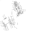
- the syringe 90 generally comprises a barrel 92, a distal end 94 including a hypodermic needle 95, a needle cover (not shown), a proximal end 93 having a lip 96, and a plunger 98.
- the distal end 94 of the syringe 90 is inserted into the open proximal end 22 of the body 20.
- the syringe 90 enters the cavity 26 and progresses distally until the distal end 94 of the syringe 90 engages the distal end 24 of the body 20.
- the distal end 94 of the syringe may simply abut the distal end 24 of the body 20, or alternatively the distal end 94 of the syringe 90 may partially enter the opening 34 and engage the collar 32, thereby providing additional protection from lateral movement of the syringe 90 (FIGS. 1 and 6A).
- the lip 96 on the proximal end 93 of the syringe 90 contacts the locking detents 58 on the finger grip 50.
- the locking detents 58 have tapered proximal edges 58a, allowing the syringe to be directed further distally, the lip 96 moving the locking detents 58 aside and entering the slot 57.
- the locking detents have blunt distal edges 58b which prevent the syringe 90 from being removed proximally from the slot 57, thereby substantially permanently locking the syringe 90 into the body 20, an important feature of the present invention.
- the needle 95 and its cover extend through the opening 34 on the collar 32 and the opening 65 on the distal end 63 of the shield 60.
- the syringe 90 may then be used in a conventional manner to deliver medication in the barrel 92.
- the medical professional typically holds the syringe by placing their index finger on a finger ledge 54, their middle finger on the other finger ledge 54, and their thumb on the end 99 of the plunger 98.
- the cover (not shown) is removed, the needle 95 is inserted into the patient, and the medication is delivered by directing the plunger 98 distally with the thumb.
- the windows 64 and 36 provide constant observation of the barrel 92 of the syringe 90, allowing the user to closely monitor delivery of the medication.
- the needle 95 is withdrawn from the patient, and the self-shielding feature of the guard 10 is engaged.
- the user holds the body, typically by placing his ring finger on the gripping surface 56 adjacent his middle finger, and moving his thumb from the plunger 98 to the other gripping surface 56.
- the index and middle fingers already adjacent the side walls 61b of the shield 60, grip the walls 61b and are moved distally, thereby sliding the shield 60 distally until it reaches the guarded position, shown in FIG. 6A.
- the cooperating detents 71 and detent pockets 40 hold the shield 60 in the unguarded position, force must be applied to move the shield 60 distally.
- the detents 71 have sloping distal edges 71a and blunt proximal edges 71b (FIG. 3B), and similarly, the proximal detent pockets 40 have sloping distal edges 40a and blunt proximal edges 40b (FIG. 5B). Because of the sloping distal edges 71a, 40a, the engagement between the detents 70 and the proximal detent pockets 40 may be overcome by pushing the shield 60 distally in relation to the body 20.
- the detents arms 70 move radially as the detents 71 move distally up the sloping edges 40a until the detents 71 leave the detent pockets 40.
- the shield may then be moved freely, the stop tab 38 traveling along the window 64, until the stop tab 38 abuts the proximal edge 66 of the window 64, reaching the guarded position.
- the detents 71 substantially simultaneously enter the distal detent pockets 42.
- the blunt proximal edges 71b of the detents engage the blunt proximal edges 42b of the distal detent pockets 42, thereby preventing the shield 60 from being moved proximally.
- the shield 60 may not be moved further distally. Thus, the shield 60 is thereby substantially permanently locked in the guarded position.
- the distal end 63 of the shield 60 passes over the needle 95, covering the needle 95.
- the needle 95 is no longer accessible, thereby substantially eliminating the risk of accidental sticks, and preventing reuse of the syringe 90.
- the guard 10 and syringe 90 may then be disposed of safely.
Claims (14)
- Schutzvorrichtung (10) für eine medizinische Kartusche (90) mit einem proximalen (93) und einem distalen (94) Ende, und einem Rand (96) an dem proximalen Ende und mit einer eigenen Nadel (95), welche sich von dem distalen Ende (94) erstreckt, wobei die Schutzvorrichtung (10) einen starren Körper (20) mit einem Hohlraum (26) enthält, welcher so ausgestaltet ist, dass er die Kartusche (90) axial darin durch ein offenes proximales Ende (22) des Körpers (20) aufnehmen kann, und mit einem distalen Ende (24) mit einer Öffnung, durch welche die Nadel (95) sich erstrecken kann, wenn die Kartusche (90) in dem Hohlraum (26) aufgenommen ist, und einer Schutzabdeckung (60), die beweglich an dem Körper (20) befestigt ist, und mit offenen proximalen (62) und distalen (63) Enden, wobei die Schutzabdeckung (60) zwischen einer ungeschützten und einer geschützten Stellung beweglich ist, wodurch die Nadel (95) auf der Kartusche freigelegt bzw. bedeckt wird, wobei die Schutzvorrichtung (10) gekennzeichnet ist durch:Seitenflächen (55) an dem proximalen Ende (22) des Körpers (20), welche ein offenes proximales Ende (51) definieren, welches mit dem Hohlraum (26) in Verbindung steht, um das proximale Ende (93) der medizinischen Kartusche (90) aufzunehmen, wobei die Seitenflächen (55) Feststellanschläge (58) enthalten, welche Schlitze (57) in den Seitenflächen (55) definieren, um im Wesentlichen dauerhaft mit dem Rand (96) an dem proximalen Ende (93) der in dem Hohlraum (26) aufgenommenen Kartusche (90) in Eingriff zu sein; einen Fingergriff (50) auf mindestens dem Körper (20) oder der Schutzabdekkung (60); undzusammenarbeitende Anschläge (40, 42, 71) an der Schutzabdeckung (60) und dem Körper (20), um die Schutzabdeckung (60) in der ungeschützten und der geschützten Stellung zu halten.
- Schutzvorrichtung (10) nach Anspruch 1, bei welcher die Feststellanschläge (58) verjüngte proximale Kanten (58a) und stumpfe distale Enden (58b) für ein im Wesentlichen andauerndes Aufnehmen des Randes (96) an dem proximalen Ende (93) der Kartusche (90) darunter aufweisen.
- Schutzvorrichtung (10) nach Anspruch 1 oder 2, bei welcher die zusammenarbeitenden Anschläge (40, 42, 71) enthalten:einen ersten Satz (40) und einen zweiten Satz (42) von in dem Körper (20) gebildeten Anschlagtaschen, wobei der zweite Satz distal von dem ersten Satz gelegen ist; undeine Anzahl an Anschlägen (71) an der Schutzvorrichtung (60), welche so ausgestaltet sind, dass sie mit den Anschlagtaschen (40, 42) in Eingriff treten können, wobei die ungeschützte Stellung dadurch definiert ist, dass die Anschläge (71) mit dem ersten Satz Anschlagtaschen (40) in Eingriff treten, und die geschützte Stellung dadurch, dass die Anschläge (71) mit dem zweiten Satz Anschlagtaschen (42) in Eingriff treten.
- Schutzvorrichtung (10) nach Anspruch 3, bei welcher die Anschläge (71) integral an die Schutzabdeckung nahe dem proximalen Ende angeformt ist.
- Schutzvorrichtung (10) nach Anspruch 3, bei welcher die Anschläge (71) abgeschrägte distale Kanten (71a) und stumpfe proximale Kanten (71b) aufweisen, und bei welcher der erste Satz Anschlagtaschen (40) abgeschrägte distale Kanten (40a) aufweist, wodurch die Schutzabdeckung (60) durch gleitendes Außereingriffbringen der Anschläge (71) aus dem ersten Satz Anschlagtaschen (40) längs der abgeschrägten distalen Kanten (71a, 40a) aus der ungeschützten Stellung bewegt werden kann .
- Schutzvorrichtung (10) nach einem der Ansprüche 3 - 5, bei welcher der zweite Satz Anschlagtaschen (42) stumpfe proximale Kanten (42b) aufweist, wodurch beim Führen der Schutzabdeckung (60) in die geschützte Stellung die stumpfen proximalen Kanten (71b) der Anschläge (71) mit den stumpfen proximalen Kanten (42b) des zweiten Satzes Anschlagtaschen (42) in Eingriff treten und verhindern, dass die Schutzabdeckung (60) proximal aus der geschützten Stellung bewegt wird.
- Schutzvorrichtung (10) nach einem der Ansprüche 1 - 6, bei welcher der Fingergriff (50) integral an das proximale Ende des Körpers (20) angeformt ist.
- Schutzvorrichtung (10) nach Anspruch 7, bei welcher der Fingergriff (50) eine "T"-Form enthält.
- Schutzvorrichtung (10) nach einem der Ansprüche 1-7, bei welcher der Fingergriff Fingerhalterungen an der Schutzabdeckung (60) enthält.
- Schutzvorrichtung (10) nach einem der Ansprüche 1 - 9, bei welcher das distale Ende (24) des Körpers (20) einen integral angeformten Kragen (32) enthält.
- Schutzvorrichtung (10) nach einem der Ansprüche 1 - 10, bei welcher
die Schlitze (57) zum Aufnehmen des Randes (96) ausgebildet sind, um zu verhindern, dass die Kartusche (90) proximal von dem Körper (20) entfernt wird. - Schutzvorrichtung (10) nach Anspruch 11, bei welcher die Feststellanschläge (58) stumpfe distale Kanten (58b) aufweisen, die verhindern, dass der Rand (96) auf der Kartusche (90) proximal von den Schlitzen (57) entfernt wird, wodurch die Kartusche (90) dauerhaft in dem Körper (20) eingekapselt ist.
- Schutzvorrichtung (10) nach einem der Ansprüche 1-12, bei welcher der Körper (20) einen rechtwinkligen Querschnitt aufweist.
- Schutzvorrichtung (10) nach einem der Ansprüche 1 - 13, bei welcher die Schutzabdeckung (60) einen rechtwinkligen Querschnitt aufweist.
Priority Applications (1)
| Application Number | Priority Date | Filing Date | Title |
|---|---|---|---|
| EP04013518A EP1464352B1 (de) | 1997-03-10 | 1998-03-09 | Spritzenschutz |
Applications Claiming Priority (2)
| Application Number | Priority Date | Filing Date | Title |
|---|---|---|---|
| US814199 | 1985-12-27 | ||
| US08/814,199 US6171283B1 (en) | 1997-03-10 | 1997-03-10 | Disposable self-shielding unit dose syringe guard |
Related Child Applications (1)
| Application Number | Title | Priority Date | Filing Date |
|---|---|---|---|
| EP04013518A Division EP1464352B1 (de) | 1997-03-10 | 1998-03-09 | Spritzenschutz |
Publications (4)
| Publication Number | Publication Date |
|---|---|
| EP0864335A2 EP0864335A2 (de) | 1998-09-16 |
| EP0864335A3 EP0864335A3 (de) | 1998-12-30 |
| EP0864335B1 true EP0864335B1 (de) | 2005-05-25 |
| EP0864335B2 EP0864335B2 (de) | 2009-05-06 |
Family
ID=25214412
Family Applications (2)
| Application Number | Title | Priority Date | Filing Date |
|---|---|---|---|
| EP98301704A Expired - Lifetime EP0864335B2 (de) | 1997-03-10 | 1998-03-09 | Spritzenschutz |
| EP04013518A Revoked EP1464352B1 (de) | 1997-03-10 | 1998-03-09 | Spritzenschutz |
Family Applications After (1)
| Application Number | Title | Priority Date | Filing Date |
|---|---|---|---|
| EP04013518A Revoked EP1464352B1 (de) | 1997-03-10 | 1998-03-09 | Spritzenschutz |
Country Status (6)
| Country | Link |
|---|---|
| US (1) | US6171283B1 (de) |
| EP (2) | EP0864335B2 (de) |
| JP (1) | JPH10248931A (de) |
| AT (2) | ATE457182T1 (de) |
| CA (1) | CA2231417C (de) |
| DE (2) | DE69830261T3 (de) |
Families Citing this family (68)
| Publication number | Priority date | Publication date | Assignee | Title |
|---|---|---|---|---|
| US6629963B2 (en) | 1996-06-20 | 2003-10-07 | Becton, Dickinson And Company | Syringe and needle shield assembly and method of sterilizing such assembly |
| US7468055B2 (en) * | 1996-06-20 | 2008-12-23 | Becton Dickinson And Company | Multi-beveled point needle and syringe having a multi-beveled point needle |
| US6159184A (en) * | 1997-03-10 | 2000-12-12 | Safety Syringes, Inc. | Disposable self-shielding unit dose syringe guard |
| US6004296A (en) * | 1997-09-30 | 1999-12-21 | Becton Dickinson France, S.A. | Lockable safety shield assembly for a prefillable syringe |
| US6719730B2 (en) | 1998-04-17 | 2004-04-13 | Becton, Dickinson And Company | Safety shield system for prefilled syringes |
| US6030366A (en) * | 1998-11-09 | 2000-02-29 | Safety Syringes, Inc. | Syringe guard system for a unit dose syringe |
| FR2801795B1 (fr) * | 1999-12-07 | 2002-07-05 | Plastef Investissements | Dispositif de support de securite pour une seringue et ensemble d'un tel dispositif et d'une seringue |
| GB0003790D0 (en) * | 2000-02-18 | 2000-04-05 | Astrazeneca Uk Ltd | Medical device |
| US6623459B1 (en) | 2000-05-05 | 2003-09-23 | Safety Syringes, Inc. | Passive needle guard for syringes |
| US6613022B1 (en) | 2000-05-05 | 2003-09-02 | Safety Syringes, Inc. | Passive needle guard for syringes |
| US6416323B1 (en) * | 2000-05-11 | 2002-07-09 | Safety Syringes, Inc. | Aspirating dental syringe with needle shield |
| US20020087360A1 (en) * | 2001-01-02 | 2002-07-04 | Pettit Stephen W. | Immunization tracking method |
| FR2821561B1 (fr) * | 2001-03-05 | 2003-05-23 | Becton Dickinson France | Seringue, ou dispositif similaire |
| US20030055685A1 (en) * | 2001-09-19 | 2003-03-20 | Safety Syringes, Inc. | Systems and methods for monitoring administration of medical products |
| FR2835753B1 (fr) | 2002-02-11 | 2004-10-29 | Plastef Investissements | Dispositif de support de securite pour une seringue et ensemble d'un tel dispositif et d'une seringue |
| CA2473901C (en) * | 2002-02-26 | 2010-09-07 | Safety Syringes, Inc. | Systems and methods for tracking pharmaceuticals within a facility |
| US20030160698A1 (en) * | 2002-02-26 | 2003-08-28 | Safety Syringes, Inc. | Systems and methods for tracking pharmaceuticals within a facility |
| US6935560B2 (en) * | 2002-02-26 | 2005-08-30 | Safety Syringes, Inc. | Systems and methods for tracking pharmaceuticals within a facility |
| US6976976B2 (en) * | 2002-03-27 | 2005-12-20 | Safety Syringes, Inc. | Syringe with needle guard injection device |
| US20040051368A1 (en) * | 2002-09-17 | 2004-03-18 | Jimmy Caputo | Systems and methods for programming pumps |
| JP4354915B2 (ja) * | 2002-11-06 | 2009-10-28 | ベクトン・ディキンソン・アンド・カンパニー | 注射器具用受動安全シールドシステム |
| AU2003291850B2 (en) * | 2002-12-20 | 2009-02-26 | Acrux Dds Pty Ltd | Dispensing device |
| AU2002953482A0 (en) * | 2002-12-20 | 2003-01-09 | Acrux Dds Pty. Ltd. | Dispensing device |
| US7500963B2 (en) * | 2003-07-22 | 2009-03-10 | Safety Syringes, Inc. | Systems and methods for automatic medical injection with safeguard |
| US7101351B2 (en) | 2003-11-03 | 2006-09-05 | Becton, Dickinson And Company | Safety device for a syringe |
| US7497847B2 (en) | 2003-11-03 | 2009-03-03 | Becton, Dickinson And Company | Safety shield system for a syringe |
| US7468054B2 (en) | 2003-11-03 | 2008-12-23 | Becton, Dickinson And Company | Safety shield system for a syringe |
| US7604613B2 (en) | 2004-01-20 | 2009-10-20 | Beckton, Dickinson And Company | Syringe having a retractable needle |
| US7344517B2 (en) | 2004-01-20 | 2008-03-18 | Becton, Dickinson And Company | Syringe having a retractable needle |
| US20060089599A1 (en) * | 2004-10-27 | 2006-04-27 | Daniel Lynn | Blood donor needle assembly and cover |
| US8062252B2 (en) | 2005-02-18 | 2011-11-22 | Becton, Dickinson And Company | Safety shield system for a syringe |
| US8372044B2 (en) * | 2005-05-20 | 2013-02-12 | Safety Syringes, Inc. | Syringe with needle guard injection device |
| US20070173770A1 (en) | 2006-01-23 | 2007-07-26 | The Medical House Plc | Injection device |
| GB0601309D0 (en) | 2006-01-23 | 2006-03-01 | Medical House The Plc | Injection device |
| US20080125725A1 (en) * | 2006-08-04 | 2008-05-29 | Nabil Dib | Syringes and IV infusion systems for clinical trials |
| GB0625169D0 (en) | 2006-12-18 | 2007-01-24 | Medical House Plc The | Improved autoinjector |
| US8057431B2 (en) | 2006-12-21 | 2011-11-15 | B. Braun Melsungen Ag | Hinged cap for needle device |
| GB0704351D0 (en) | 2007-03-07 | 2007-04-11 | Medical House Plc The | Improved autoinjector |
| US9265898B2 (en) * | 2007-09-12 | 2016-02-23 | Wolfe Tory Medical, Inc. | Applicator for oropharyngeal anesthetic |
| SI2240222T1 (en) | 2008-01-11 | 2018-08-31 | Ucb Biopharma Sprl | SYSTEMS FOR MEDICATION OF PATIENTS WITH REVOMATOID ARTS |
| US8123082B2 (en) | 2008-01-22 | 2012-02-28 | McNeil-AB | Hand-held dispensing device |
| CA2714373C (en) * | 2008-02-15 | 2017-09-19 | Becton, Dickinson And Company | Safety needle assembly |
| US8052645B2 (en) | 2008-07-23 | 2011-11-08 | Avant Medical Corp. | System and method for an injection using a syringe needle |
| CA3142745A1 (en) | 2008-05-20 | 2009-11-26 | Avant Medical Corp. | Autoinjector system |
| US8177749B2 (en) | 2008-05-20 | 2012-05-15 | Avant Medical Corp. | Cassette for a hidden injection needle |
| USD641078S1 (en) | 2008-12-29 | 2011-07-05 | Ucb Pharma, S.A. | Medical syringe with needle tip cap |
| SI2326371T1 (sl) | 2008-07-18 | 2019-12-31 | Ucb Biopharma Sprl | Sistem za dajanje zdravila za bolnike z revmatoidnim artritisom |
| GB2463071A (en) * | 2008-09-02 | 2010-03-03 | Owen Mumford Ltd | Auto-injector syringe with safety shield |
| US8439870B2 (en) * | 2008-09-10 | 2013-05-14 | B. Braun Medical Inc. | Safety needle assembly and methods |
| GB0823066D0 (en) * | 2008-12-18 | 2009-01-28 | Medical House Plc The | Safety syringe for autoinjector |
| GB2469672B (en) | 2009-04-23 | 2013-09-25 | Medical House Ltd | Improved autoinjector |
| US9526846B2 (en) | 2009-08-19 | 2016-12-27 | Safety Syringes, Inc. | Patient-contact activated needle stick safety device |
| WO2011040222A1 (ja) * | 2009-09-30 | 2011-04-07 | テルモ株式会社 | 注射針組立体及び薬剤注射装置 |
| US8920385B2 (en) | 2010-05-05 | 2014-12-30 | Safety Syringes, Inc. | Extended finger flange for syringe systems |
| HUE042822T2 (hu) | 2011-04-20 | 2019-07-29 | Amgen Inc | Automata befecskendezõ szerkezet |
| USD808010S1 (en) | 2012-04-20 | 2018-01-16 | Amgen Inc. | Injection device |
| USD898908S1 (en) | 2012-04-20 | 2020-10-13 | Amgen Inc. | Pharmaceutical product cassette for an injection device |
| US10492990B2 (en) | 2013-03-15 | 2019-12-03 | Amgen Inc. | Drug cassette, autoinjector, and autoinjector system |
| WO2014144096A1 (en) | 2013-03-15 | 2014-09-18 | Amgen Inc. | Drug cassette, autoinjector, and autoinjector system |
| EP2784766A1 (de) | 2013-03-28 | 2014-10-01 | F. Hoffmann-La Roche AG | Übungsvorrichtung für Arzneimitteleinspritzvorrichtungen und Rückstellvorrichtung zum Zurückstellen einer solchen Übungsvorrichtung |
| CN105764551B (zh) * | 2013-12-05 | 2019-07-26 | 诺和诺德股份有限公司 | 用于医疗注射装置的壳体 |
| USD765838S1 (en) | 2015-03-26 | 2016-09-06 | Tech Group Europe Limited | Syringe retention clip |
| PT3341056T (pt) * | 2015-08-24 | 2022-09-16 | Adamis Pharmaceuticals Corp | Dispositivos de seringa |
| KR101911319B1 (ko) * | 2017-01-06 | 2018-10-24 | 김성욱 | 약물 주입 장치 |
| GB2563029B (en) | 2017-05-30 | 2022-06-08 | Janssen Pharmaceuticals Inc | Grip accessory for a manual injection device |
| GB2563027B (en) | 2017-05-30 | 2022-04-06 | Janssen Pharmaceuticals Inc | Grip accessory for a manual injection device |
| WO2019068109A1 (en) | 2017-09-29 | 2019-04-04 | West Pharmaceutical Services, Inc. | CASE WITH SYRINGE HOLDING FEATURE |
| JP7285842B2 (ja) * | 2017-12-13 | 2023-06-02 | リジェネロン・ファーマシューティカルズ・インコーポレイテッド | 正確な用量の送達のためのデバイス及び方法 |
Family Cites Families (27)
| Publication number | Priority date | Publication date | Assignee | Title |
|---|---|---|---|---|
| US4927416A (en) | 1987-12-02 | 1990-05-22 | National Medical Device Corporation | User-protective hypodermic syringe holder |
| US5059185A (en) * | 1988-03-01 | 1991-10-22 | Ryan Medical, Inc. | Safety needled medical devices |
| US5067945A (en) * | 1988-03-01 | 1991-11-26 | Ryan Medical, Inc. | Safety needled medical devices capable of one-handed manipulation |
| US5312370A (en) * | 1988-06-28 | 1994-05-17 | Sherwood Medical Company | Combined syringe and needle shield |
| US4969877A (en) | 1988-10-19 | 1990-11-13 | The Pascall Medical Corporation | Syringe |
| US5002537A (en) * | 1989-10-23 | 1991-03-26 | Gte Products Corporation | Hypodermic syringe |
| US4990142A (en) * | 1989-10-23 | 1991-02-05 | Gte Products Corporation | Hypodermic syringe |
| US5098382A (en) * | 1989-12-11 | 1992-03-24 | Habley Medical Technology Corporation | Safety module-activator reshielding tool |
| US5624400A (en) * | 1990-05-09 | 1997-04-29 | Safety Syringes, Inc. | Disposable self-shielding aspirating syringe |
| US5437647A (en) * | 1990-05-09 | 1995-08-01 | Safety Syringes, Inc. | Disposable self-shielding aspirating syringe |
| NL9002552A (nl) | 1990-09-05 | 1992-04-01 | Advanced Protective Injection | Infusie- of transfusienaaldsamenstel. |
| US5242416A (en) † | 1992-01-09 | 1993-09-07 | Hutson Clifford L | Shield assembly for needle syringes |
| US5417660A (en) | 1992-02-03 | 1995-05-23 | T. A. Kershenstine | Self-locking syringe holder for use with a hypodermic syringe |
| US5201720A (en) * | 1992-04-21 | 1993-04-13 | Joseph Borgia | Syringe holding and ejecting assembly |
| US5215535A (en) | 1992-05-20 | 1993-06-01 | Gettig Technologies Incorporated | Needle protector apparatus |
| US5269766A (en) * | 1992-06-09 | 1993-12-14 | Habley Medical Technology Corporation | Dental syringe having an automatically retractable medication carpule and needle cannula |
| US5336185A (en) | 1992-12-31 | 1994-08-09 | Lynch Richard A | Protection device for syringe needles |
| US5344407A (en) | 1993-05-04 | 1994-09-06 | Ryan Dana W | Safety holder for pre-filled disposable syringe cartridge |
| US5433712A (en) * | 1993-06-10 | 1995-07-18 | Donald E. Stiles | Self-sheathing hypodermic syringe |
| US5445620A (en) | 1993-09-17 | 1995-08-29 | Habley Medical Technology Corp. | Disposable safety syringe with retractable shuttle for Wyeth medication cartridge |
| US5498244A (en) | 1993-09-22 | 1996-03-12 | American Home Products Corporation | Safety guard for medical instruments |
| GB2283425A (en) * | 1993-10-19 | 1995-05-10 | Yong Siang Toi | Protective sheath for a syringe |
| US5514107A (en) | 1994-02-10 | 1996-05-07 | Habley Medical Technology Corporation | Safety syringe adapter for cartridge-needle unit |
| US5385557A (en) | 1994-04-04 | 1995-01-31 | Thompson; Clarence J. | Shielding device for a syringe needle |
| US5496286A (en) * | 1994-08-17 | 1996-03-05 | Sterling Winthrop | Hypodermic syringe holder with disposable body |
| FR2733687B1 (fr) * | 1995-05-04 | 1997-10-03 | Brunel Marc | Procede de fabrication d'un dispositif d'injection du type pre-rempli renfermant une dose de liquide a injecter, et dispositif d'injection realise |
| US5569211A (en) | 1995-06-05 | 1996-10-29 | Lekhgolts; Victor | Single-use hypodermic syringe |
-
1997
- 1997-03-10 US US08/814,199 patent/US6171283B1/en not_active Expired - Lifetime
-
1998
- 1998-03-06 CA CA002231417A patent/CA2231417C/en not_active Expired - Lifetime
- 1998-03-09 JP JP10056649A patent/JPH10248931A/ja active Pending
- 1998-03-09 EP EP98301704A patent/EP0864335B2/de not_active Expired - Lifetime
- 1998-03-09 AT AT04013518T patent/ATE457182T1/de not_active IP Right Cessation
- 1998-03-09 EP EP04013518A patent/EP1464352B1/de not_active Revoked
- 1998-03-09 DE DE69830261T patent/DE69830261T3/de not_active Expired - Lifetime
- 1998-03-09 DE DE69841501T patent/DE69841501D1/de not_active Expired - Lifetime
- 1998-03-09 AT AT98301704T patent/ATE296133T1/de not_active IP Right Cessation
Also Published As
| Publication number | Publication date |
|---|---|
| EP0864335A3 (de) | 1998-12-30 |
| EP0864335B2 (de) | 2009-05-06 |
| EP1464352A3 (de) | 2005-01-12 |
| DE69841501D1 (de) | 2010-03-25 |
| EP0864335A2 (de) | 1998-09-16 |
| ATE296133T1 (de) | 2005-06-15 |
| DE69830261T2 (de) | 2006-02-02 |
| CA2231417C (en) | 2006-08-01 |
| EP1464352B1 (de) | 2010-02-10 |
| CA2231417A1 (en) | 1998-09-10 |
| DE69830261D1 (de) | 2005-06-30 |
| JPH10248931A (ja) | 1998-09-22 |
| EP1464352A2 (de) | 2004-10-06 |
| DE69830261T3 (de) | 2009-09-17 |
| US6171283B1 (en) | 2001-01-09 |
| ATE457182T1 (de) | 2010-02-15 |
Similar Documents
| Publication | Publication Date | Title |
|---|---|---|
| EP0864335B1 (de) | Spritzenschutz | |
| US6030366A (en) | Syringe guard system for a unit dose syringe | |
| EP1019123B1 (de) | Schutzabdeckung einer einwegdosierungsspritze | |
| US6623459B1 (en) | Passive needle guard for syringes | |
| EP1284769B1 (de) | Passive nadelabschirmung für spritzen | |
| US6872194B2 (en) | Disposable self-shielding syringe guard | |
| US7455661B2 (en) | Safety shield system for prefilled syringe | |
| EP0966983B1 (de) | Schutzhülse für vorgefüllte Spritzen | |
| US4946447A (en) | Protective cover for hypodermic needle | |
| MXPA98001899A (en) | Disposable self-protection guard for unita dosage syringe |
Legal Events
| Date | Code | Title | Description |
|---|---|---|---|
| PUAI | Public reference made under article 153(3) epc to a published international application that has entered the european phase |
Free format text: ORIGINAL CODE: 0009012 |
|
| AK | Designated contracting states |
Kind code of ref document: A2 Designated state(s): AT BE CH DE DK ES FI FR GB GR IE IT LI LU MC NL PT SE |
|
| AX | Request for extension of the european patent |
Free format text: AL;LT;LV;MK;RO;SI |
|
| PUAL | Search report despatched |
Free format text: ORIGINAL CODE: 0009013 |
|
| AK | Designated contracting states |
Kind code of ref document: A3 Designated state(s): AT BE CH DE DK ES FI FR GB GR IE IT LI LU MC NL PT SE |
|
| AX | Request for extension of the european patent |
Free format text: AL;LT;LV;MK;RO;SI |
|
| 17P | Request for examination filed |
Effective date: 19990510 |
|
| AKX | Designation fees paid |
Free format text: AT BE CH DE DK ES FI FR GB GR IE IT LI LU MC NL PT SE |
|
| 17Q | First examination report despatched |
Effective date: 20011101 |
|
| GRAP | Despatch of communication of intention to grant a patent |
Free format text: ORIGINAL CODE: EPIDOSNIGR1 |
|
| GRAS | Grant fee paid |
Free format text: ORIGINAL CODE: EPIDOSNIGR3 |
|
| GRAA | (expected) grant |
Free format text: ORIGINAL CODE: 0009210 |
|
| AK | Designated contracting states |
Kind code of ref document: B1 Designated state(s): AT BE CH DE DK ES FI FR GB GR IE IT LI LU MC NL PT SE |
|
| PG25 | Lapsed in a contracting state [announced via postgrant information from national office to epo] |
Ref country code: NL Free format text: LAPSE BECAUSE OF FAILURE TO SUBMIT A TRANSLATION OF THE DESCRIPTION OR TO PAY THE FEE WITHIN THE PRESCRIBED TIME-LIMIT Effective date: 20050525 Ref country code: LI Free format text: LAPSE BECAUSE OF FAILURE TO SUBMIT A TRANSLATION OF THE DESCRIPTION OR TO PAY THE FEE WITHIN THE PRESCRIBED TIME-LIMIT Effective date: 20050525 Ref country code: FI Free format text: LAPSE BECAUSE OF FAILURE TO SUBMIT A TRANSLATION OF THE DESCRIPTION OR TO PAY THE FEE WITHIN THE PRESCRIBED TIME-LIMIT Effective date: 20050525 Ref country code: CH Free format text: LAPSE BECAUSE OF FAILURE TO SUBMIT A TRANSLATION OF THE DESCRIPTION OR TO PAY THE FEE WITHIN THE PRESCRIBED TIME-LIMIT Effective date: 20050525 Ref country code: BE Free format text: LAPSE BECAUSE OF FAILURE TO SUBMIT A TRANSLATION OF THE DESCRIPTION OR TO PAY THE FEE WITHIN THE PRESCRIBED TIME-LIMIT Effective date: 20050525 Ref country code: AT Free format text: LAPSE BECAUSE OF FAILURE TO SUBMIT A TRANSLATION OF THE DESCRIPTION OR TO PAY THE FEE WITHIN THE PRESCRIBED TIME-LIMIT Effective date: 20050525 |
|
| REG | Reference to a national code |
Ref country code: GB Ref legal event code: FG4D |
|
| REG | Reference to a national code |
Ref country code: CH Ref legal event code: EP |
|
| REG | Reference to a national code |
Ref country code: IE Ref legal event code: FG4D |
|
| REF | Corresponds to: |
Ref document number: 69830261 Country of ref document: DE Date of ref document: 20050630 Kind code of ref document: P |
|
| RAP2 | Party data changed (patent owner data changed or rights of a patent transferred) |
Owner name: SAFETY SYRINGES, INC. |
|
| PG25 | Lapsed in a contracting state [announced via postgrant information from national office to epo] |
Ref country code: SE Free format text: LAPSE BECAUSE OF FAILURE TO SUBMIT A TRANSLATION OF THE DESCRIPTION OR TO PAY THE FEE WITHIN THE PRESCRIBED TIME-LIMIT Effective date: 20050825 Ref country code: GR Free format text: LAPSE BECAUSE OF FAILURE TO SUBMIT A TRANSLATION OF THE DESCRIPTION OR TO PAY THE FEE WITHIN THE PRESCRIBED TIME-LIMIT Effective date: 20050825 Ref country code: DK Free format text: LAPSE BECAUSE OF FAILURE TO SUBMIT A TRANSLATION OF THE DESCRIPTION OR TO PAY THE FEE WITHIN THE PRESCRIBED TIME-LIMIT Effective date: 20050825 |
|
| PG25 | Lapsed in a contracting state [announced via postgrant information from national office to epo] |
Ref country code: ES Free format text: LAPSE BECAUSE OF FAILURE TO SUBMIT A TRANSLATION OF THE DESCRIPTION OR TO PAY THE FEE WITHIN THE PRESCRIBED TIME-LIMIT Effective date: 20050905 |
|
| PG25 | Lapsed in a contracting state [announced via postgrant information from national office to epo] |
Ref country code: PT Free format text: LAPSE BECAUSE OF FAILURE TO SUBMIT A TRANSLATION OF THE DESCRIPTION OR TO PAY THE FEE WITHIN THE PRESCRIBED TIME-LIMIT Effective date: 20051027 |
|
| NLT2 | Nl: modifications (of names), taken from the european patent patent bulletin |
Owner name: SAFETY SYRINGES, INC. Effective date: 20050824 |
|
| REG | Reference to a national code |
Ref country code: CH Ref legal event code: PL |
|
| NLV1 | Nl: lapsed or annulled due to failure to fulfill the requirements of art. 29p and 29m of the patents act | ||
| PG25 | Lapsed in a contracting state [announced via postgrant information from national office to epo] |
Ref country code: IE Free format text: LAPSE BECAUSE OF NON-PAYMENT OF DUE FEES Effective date: 20060309 |
|
| PLBI | Opposition filed |
Free format text: ORIGINAL CODE: 0009260 |
|
| PG25 | Lapsed in a contracting state [announced via postgrant information from national office to epo] |
Ref country code: MC Free format text: LAPSE BECAUSE OF NON-PAYMENT OF DUE FEES Effective date: 20060331 Ref country code: LU Free format text: LAPSE BECAUSE OF NON-PAYMENT OF DUE FEES Effective date: 20060331 |
|
| ET | Fr: translation filed | ||
| 26 | Opposition filed |
Opponent name: BECTON, DICKINSON AND COMPANY Effective date: 20060227 |
|
| PLAX | Notice of opposition and request to file observation + time limit sent |
Free format text: ORIGINAL CODE: EPIDOSNOBS2 |
|
| PLBB | Reply of patent proprietor to notice(s) of opposition received |
Free format text: ORIGINAL CODE: EPIDOSNOBS3 |
|
| REG | Reference to a national code |
Ref country code: IE Ref legal event code: MM4A |
|
| APBM | Appeal reference recorded |
Free format text: ORIGINAL CODE: EPIDOSNREFNO |
|
| APBP | Date of receipt of notice of appeal recorded |
Free format text: ORIGINAL CODE: EPIDOSNNOA2O |
|
| APAH | Appeal reference modified |
Free format text: ORIGINAL CODE: EPIDOSCREFNO |
|
| APBU | Appeal procedure closed |
Free format text: ORIGINAL CODE: EPIDOSNNOA9O |
|
| APBU | Appeal procedure closed |
Free format text: ORIGINAL CODE: EPIDOSNNOA9O |
|
| PUAH | Patent maintained in amended form |
Free format text: ORIGINAL CODE: 0009272 |
|
| STAA | Information on the status of an ep patent application or granted ep patent |
Free format text: STATUS: PATENT MAINTAINED AS AMENDED |
|
| 27A | Patent maintained in amended form |
Effective date: 20090506 |
|
| AK | Designated contracting states |
Kind code of ref document: B2 Designated state(s): AT BE CH DE DK ES FI FR GB GR IE IT LI LU MC NL PT SE |
|
| REG | Reference to a national code |
Ref country code: ES Ref legal event code: FD2A Effective date: 20060310 |
|
| PLAB | Opposition data, opponent's data or that of the opponent's representative modified |
Free format text: ORIGINAL CODE: 0009299OPPO |
|
| REG | Reference to a national code |
Ref country code: FR Ref legal event code: PLFP Year of fee payment: 19 |
|
| REG | Reference to a national code |
Ref country code: FR Ref legal event code: PLFP Year of fee payment: 20 |
|
| PGFP | Annual fee paid to national office [announced via postgrant information from national office to epo] |
Ref country code: DE Payment date: 20170222 Year of fee payment: 20 Ref country code: FR Payment date: 20170221 Year of fee payment: 20 |
|
| PGFP | Annual fee paid to national office [announced via postgrant information from national office to epo] |
Ref country code: GB Payment date: 20170224 Year of fee payment: 20 |
|
| PGFP | Annual fee paid to national office [announced via postgrant information from national office to epo] |
Ref country code: IT Payment date: 20170221 Year of fee payment: 20 |
|
| REG | Reference to a national code |
Ref country code: DE Ref legal event code: R071 Ref document number: 69830261 Country of ref document: DE |
|
| REG | Reference to a national code |
Ref country code: GB Ref legal event code: PE20 Expiry date: 20180308 |
|
| PG25 | Lapsed in a contracting state [announced via postgrant information from national office to epo] |
Ref country code: GB Free format text: LAPSE BECAUSE OF EXPIRATION OF PROTECTION Effective date: 20180308 |