EP0864123B1 - Two-stage chemical mixing system - Google Patents
Two-stage chemical mixing system Download PDFInfo
- Publication number
- EP0864123B1 EP0864123B1 EP96939567A EP96939567A EP0864123B1 EP 0864123 B1 EP0864123 B1 EP 0864123B1 EP 96939567 A EP96939567 A EP 96939567A EP 96939567 A EP96939567 A EP 96939567A EP 0864123 B1 EP0864123 B1 EP 0864123B1
- Authority
- EP
- European Patent Office
- Prior art keywords
- mix
- chemical
- level
- drum
- vessel
- Prior art date
- Legal status (The legal status is an assumption and is not a legal conclusion. Google has not performed a legal analysis and makes no representation as to the accuracy of the status listed.)
- Expired - Lifetime
Links
Images

Classifications
-
- G—PHYSICS
- G05—CONTROLLING; REGULATING
- G05D—SYSTEMS FOR CONTROLLING OR REGULATING NON-ELECTRIC VARIABLES
- G05D9/00—Level control, e.g. controlling quantity of material stored in vessel
-
- G—PHYSICS
- G05—CONTROLLING; REGULATING
- G05D—SYSTEMS FOR CONTROLLING OR REGULATING NON-ELECTRIC VARIABLES
- G05D11/00—Control of flow ratio
- G05D11/02—Controlling ratio of two or more flows of fluid or fluent material
- G05D11/13—Controlling ratio of two or more flows of fluid or fluent material characterised by the use of electric means
- G05D11/135—Controlling ratio of two or more flows of fluid or fluent material characterised by the use of electric means by sensing at least one property of the mixture
- G05D11/138—Controlling ratio of two or more flows of fluid or fluent material characterised by the use of electric means by sensing at least one property of the mixture by sensing the concentration of the mixture, e.g. measuring pH value
-
- G—PHYSICS
- G05—CONTROLLING; REGULATING
- G05D—SYSTEMS FOR CONTROLLING OR REGULATING NON-ELECTRIC VARIABLES
- G05D11/00—Control of flow ratio
- G05D11/02—Controlling ratio of two or more flows of fluid or fluent material
- G05D11/13—Controlling ratio of two or more flows of fluid or fluent material characterised by the use of electric means
- G05D11/131—Controlling ratio of two or more flows of fluid or fluent material characterised by the use of electric means by measuring the values related to the quantity of the individual components
- G05D11/133—Controlling ratio of two or more flows of fluid or fluent material characterised by the use of electric means by measuring the values related to the quantity of the individual components with discontinuous action
Definitions
- the present invention is a chemical blending or mixing system.
- the invention is a system for mixing concentrated chemicals from two or more chemical components for subsequent use in semiconductor fabrication facilities.
- Chemical generation or mixing systems are used in a variety of industrial applications to blend two or more components or constituents to a desired concentration.
- concentrated chemicals which are usually provided by commercial chemical suppliers in solution with water
- DI deionized or ultra pure water
- Table 1 lists a number of chemicals used in semiconductor fabrication facilities, and the concentration (in weight %) in which these chemicals are typically provided by suppliers.
- the concentrated chemicals described above are commonly diluted with DI water (i.e., a diluent) to desired concentrations or assays. Concentrations in these applications are typically described in terms of weight % (weight percent) of concentrated or pure chemical in water. Hydrofluoric Acid (HF), for example, is often diluted with ultra pure water to concentrations ranging from about 0.5% -5% HF by weight when used for etching and cleaning processes. Tetramethyl Ammonium Hydroxide (TMAH) is often diluted co about 2.38 weight % for use as a positive photoresist developer. Non-aqueous blended chemicals, and blended chemicals with three or more components, can also be generated.
- DI water i.e., a diluent
- TMAH Tetramethyl Ammonium Hydroxide
- Chemical mixing systems blend the chemicals to a desired concentration which is sometimes known as the nominal or qualification concentration. A high degree of accuracy is also required.
- the range or window of acceptable concentrations surrounding the qualification concentration is known as the qualification range, and can be defined as a weight % error with respect to the qualification concentration, or by upper and lower qualification range concentrations.
- Chemical blending systems of the type described above are commercially available from a number of sources including FSI International of Chaska, Minnesota and Applied Chemical Solutions of Hollister, California. They are also disclosed generally in the Geatz U.S. Patent 5,148,945 and the Ferri, Jr. et al. U.S. Patent 5,330,072.
- One embodiment of the present invention is a chemical mixing system for preparing an admixture comprising a concentration of a chemical species which is within a defined qualification range.
- the chemical mixing system includes a mix vessel having an internal volume suitable for preparing a batch from ingredients comprising a diluent and a concentrated solution containing a relatively high concentration of the chemical species relative to the qualification range. The ingredients are combined in amounts effective for providing the batch with a corrective concentration of the chemical species relative to a measured concentration of the chemical species in the admixture.
- the mix vessel is adapted to receive the concentrated solution and the diluent from first and second supply sources, respectively.
- a mix drum has an internal volume for holding a supply of the admixture.
- the internal volume of the mix drum is of a size sufficient for holding a plurality of batches prepared in the mix vessel.
- the mix drum is coupled to the mix vessel so that said plurality of batches prepared in the mix vessel can be transported to the internal volume of the mix drum in order to replenish the supply of, and controllably adjust the concentration of the first chemical species in the mixed chemical admixture.
- a control system is responsive to information comprising the measured concentration of the chemical species in the admixture, wherein said control system is capable of generating valve control signals for controlling the amounts of the concentrated solution and the diluent which are combined in the mix vessel when a batch is prepared so that the prepared batch comprises a corrective concentration of the chemical species relative to the measured concentration of the chemical species in the admixture.
- a plurality of control valves are disposed in the chemical mixing system at positions effective for regulating the amount of the concentrated solution and the diluent added to the mix vessels from the first and second supply sources, respectively.
- the control valves are actuated in response to information comprising the valve control signals generated by the control system.
- the present invention also involves a process, as defined by claim 22, for controlling an amount of a chemical species in a chemical admixture.
- One step is providing a supply of the admixture, wherein the admixture comprises a concentration of the chemical-species.
- Another step is measuring the concentration of the chemical species in the admixture.
- Another step is determining if the measured concentration is within a defined qualification range.
- Another step is preparing a batch comprising a corrective concentration of the chemical species relative to the measured concentration of the chemical species in the admixture.
- the step of preparing the batch includes comprises the following three steps. First, the preparing step includes providing ingredients comprising a concentrated solution and a diluent, wherein the concentrated solution contains a relatively high concentration of the chemical species relative to the qualification range.
- the preparing step includes providing a mix vessel having an internal volume suitable for preparing the batch, wherein the mix vessel is adapted to receive the concentrated solution and the diluent from first and second supply sources, respectively, and wherein the process is provided with a plurality of chemical constituent sensors capable of generating constituent sensor signals in representative of the respective amounts of the concentrated solution and the diluent which are added to the internal volume of the mix vessel.
- the preparing step includes adding amounts of said ingredients to the mix vessel effective to provide the batch with the corrective concentration of the chemical species, wherein the amount of said ingredients added to the mix vessel is controlled in response to information comprising the constituent sensor signals and to the measured concentration of the chemical species in the mixed chemical admixture.
- the process further includes the step of combining the batch with the admixture supply in order to controllably adjust the concentration of the chemical species in the admixture.
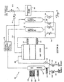
- a chemical mixing system 10 in accordance with the present invention is illustrated generally in Figure 1.
- system 10 includes mix vessel 12, mix drum 14, pressure/vacuum vessels 15 and 17, concentrated chemical inlet 16 and diluent inlet 18. Relatively small batches of chemical are mixed in mix vessel 12 and subsequently transferred to mix drum 14. The chemical in mix drum 14 is then blended together and stored until it is delivered to a point-of-use in a semiconductor fabrication facility.
- mix vessel 12 has a nominal fluid capacity of about 1.5 gallons (5 liters), while mix drum 14 has a nominal capacity of about 15 gallons (50 liters).
- the volume ratios of the chemical constituents mixed within mix vessel 12 are controlled as a function of the monitored concentration of the mixed chemical within drum 14. In this manner mixing system 10 effectively utilizes a two-stage, batch averaging process to mix the chemical constituents to the desired concentration with a high degree of accuracy.
- Vessels 12, 15 and 17 and drum 14 are fabricated from a material such as Teflon PFA (perfluoroalkoxy) or ultra high molecular weight polyethylene which is resistant to corrosion by the blended chemical.
- the illustrated embodiment of mixing system 10 is configured for diluting and mixing concentrated hydrofluoric acid (HF) with ultra-pure water (UPW).
- Concentrated chemical inlet 16 is therefore adapted to be fluidly coupled to a drum or other source of concentrated HF, while diluent inlet 18 is adapted to be fluidly coupled to a pressurized source of ultra-pure water.
- Concentrated chemical inlet 16 is fluidly coupled to mix vessel 12 by line 20.
- An on-off control valve V1 is positioned in line 20 to control the flow of HF through the line.
- Diluent inlet 18 is fluidly coupled to mix vessel 12 by line 24.
- On-off control valve V2 is positioned in line 24 to control the flow of ultra-pure water through the line.
- the fluid level within mix vessel 12 is monitored by first, second, third, fourth and seventh mix vessel level sensors S1, S2, S3, S4 and S7, respectively.
- a vacuum/pressure/vent system 36 is fluidly coupled to the mix vessel 12 and pressure/vacuum vessels 15 and 17, and is used to motivate the chemical constituents and mixed chemicals through system 10.
- Mix vessel 12 is fluidly coupled to mix drum 14 by mix drum line 38.
- the flow of chemical through line 38 is controlled by on-off control valve V3.
- the fluid level within mix drum 14 is monitored by first and second mix drum level sensors S5 and S6, respectively.
- a line 54 is used to transfer mixed chemical from mix drum 14 to pressure/vacuum vessels 15 and 17.
- On-off control valves V4 and V5 are positioned in line 54 to control the flow of chemical into pressure/vacuum vessels 15 and 17, respectively. From pressure/vacuum vessels 15 and 17, chemical can be transferred to a point-of-use station (not shown) through distribution line 51 and on-off control valve V10 when valve V9 is closed.
- On-off control valves V7 and V8 are positioned to control the flow of chemical from pressure/vacuum vessels 15 and 17, respectively, into line 51.
- chemical in line 51 can be recirculated back to mix drum 14 through recirculation line 53 and on-off control valve V9 when valve V10 is closed.
- Vacuum/pressure/vent system 36 is a conventional system which includes control valves (not separately shown) which couple mix vessel 12 and pressure/vacuum vessels 15 and 17 to both vacuum and pressure sources (also not shown).
- Systems of this type are well known and described, for example, in the Geatz U.S. Patent 5,148,945 and the Ferri, Jr. et al. U.S. Patent 5,330,072. Briefly, when it is desired to transfer chemical into one of vessels 12, 15 or 17 from a source, the associated control valve between the source and vessel is closed, and vacuum/pressure/vent system 36 is operated to create a vacuum within the vessel. The associated control valve between the source and vessel is then opened to allow the vacuum to draw chemical into the vessel from the source. To transfer chemical from one of vessels 12.
- the associated control valve between che vessel and the downstream location is opened, and the vacuum/pressure/vent system 36 is operated to pressurize the vessel and force the chemical therefrom.
- system 36 vents the vessel to which the chemical constituent is to be transferred.
- Conventional pumps e.g., diaphragm pumps
- Probe 56 is located in line 51 in the embodiment shown. In other embodiments (not shown), probe 56 can be positioned in other locations such as in lines 53 or 54 or within mix drum 14, depending on the characteristics of the monitor.
- FIG. 2 is a block diagram of a control system 60 used to control the operation of chemical mixing system 10.
- control system 60 includes a controller 62 which is interfaced to vacuum/pressure/vent system 36, control valves V1-V9 and level sensors S1-S7.
- Conductivity probe 56 is coupled to controller 62 through a conductivity monitor 66.
- controller 62 is a digital programmable logic array in one embodiment, although hard-wired, microprocessor-based and other conventional control systems can also be used.
- Monitor 66 drives conductivity probe 56 and processes signals received from the probe to generate digital concentration values representative of the weight percent concentration of the concentrated chemical flowing past the probe.
- Probes such as 56 and monitors such as 66 are well known and commercially available from a number of manufacturers such as Horiba Instruments Inc.
- a programmable conductivity monitor 66 is used in one embodiment of chemical mixing system 10.
- the programmable monitor 66 can be programmed with an Upper Qualification Range Setpoint and a Lower Qualification Range Setpoint.
- the Upper and Lower Qualification Range Setpoints are representative of mixed chemical concentrations above and below an ideal or desired mixed chemical concentration, respectively, and represent an acceptable window or range of final mixed chemical concentrations.
- the programmable monitor 66 provides signals to controller 62 indicating whether the measured chemical concentration is greater than the Upper Qualification Range Setpoint, less than the Lower Qualification Range Setpoint, or within the desired concentration range between the Upper and Lower Qualification Range Setpoints.
- Level sensors S1-S7 are capacitive-type sensors in one embodiment of mixing system 10. These sensors S1-S7 are positioned at locations on the exterior of mix vessel 12 and mix drum 14 which correspond co predetermined levels or volumes of chemical within the vessel and drum. When the level of chemical within the mix vessel 12 and drum 14 increases or decreases to the level at which the sensors S1-S7 are located, the sensors provide signals representative of the level change condition to controller 62. Other types of level sensors such as those which provide a continuous indication of the chemical level can also be used.
- control valves V1-V9 are air-operated on-off valves.
- the supply of air used to actuate the control valves V1-V9 is coupled to the valves through solenoid valves (not separately shown) which are interfaced directly to controller 62.
- Control valves V1-V9 are therefore effectively responsive to and actuated by controller 62.
- First mix vessel level sensor S1 is positioned at a first volume level on vessel 12. The first volume level corresponds approximately to a first chemical constituent volume that will yield a mix vessel batch having the desired concentration (i.e., the desired volume proportion of first chemical constituent to the nominal mix batch volume).
- Second mix vessel level sensor S2 is positioned at a second volume level on mix vessel 12. The second volume level is a volume level which is greater than the first volume level by an amount which corresponds approximately to a second chemical constituent volume that will yield a mix vessel batch having the desired concentration (i.e., greater than the first volume level by an amount equal to the desired volume proportion of the second chemical constituent to the nominal mix batch volume).
- Third mix vessel level sensor S3 is positioned at a third volume level on vessel 12.
- the third volume level is less than the second volume level, but greater than the first volume level by an amount which corresponds approximately to a second chemical constituent volume that will yield a mix vessel batch having a concentration which is slightly less than the desired concentration.
- Fourth mix vessel level sensor S4 is positioned at a fourth volume level on vessel 12. The fourth volume level is greater than the second volume level, and is greater than the first volume level by an amount which corresponds approximately to a second chemical constituent volume that will yield a mix vessel batch having a concentration which is slightly greater than the desired concentration.
- the amount by which the concentration of the mix vessel batches is less and greater than the desired concentration, and therefore the third and fourth volume levels, will depend upon a number of factors including the "concentration" of the concentrated chemical as supplied by commercial vendors, the ratio of the nominal mix vessel batch volume to the desired average level of mixed chemical in the mix drum 14, and the rate at which it is desired to vary the concentration of the mixed chemical within the mix drum by the addition of each mix vessel batch.
- one embodiment of chemical mixing system 10 is configured to blend ultra-pure water (the first chemical constituent) with concentrated HF (49% HF, the second chemical constituent) to a concentration of 4.9 weight % HF.
- the nominal mix batch volume in this embodiment is 1.5 gallons.
- vessel 12 should be filled with 1.35 gallons of ultra-pure water, and 0.15 gallons of concentrated HF.
- the first mix vessel level sensor S1 is therefore positioned at a level at which the sensor will provide signals indicating when the mix vessel 12 is filled to a volume level of 1.35 gallons.
- the second mix vessel level sensor S2 is positioned at a level at which the sensor will provide signals indicating when the mix vessel 12 is filled to a volume level of 1.5 gallons.
- the third mix vessel level sensor S3 and the fourth mix vessel level sensor S4 are set at volume levels of about 1.46 gallons and 1.54 gallons, respectively.
- Mix vessel batches made by filling mix vessel 12 beyond the first volume level to these third and fourth volume levels will have a concentration of about 3.6 and 6.2 weight % HF, respectively. Assuming the mix drum is filled to a level of about 10 gallons, the addition of mix batches at these concentration levels will change the concentration of the mixed chemical within the mix drum by about 0.1 weight %.
- First mix drum level sensor S5 is positioned at a first or relatively low volume level on mix drum 14.
- Second mix drum level sensor S6 is positioned at a second or relatively high volume level on the mix drum 14. In the embodiment described above where mix drum 14 has a nominal capacity of about 15 gallons, first mix drum sensor S5 is set to measure a relatively low volume level of about 2 gallons, and second mix drum sensor S6 is set to measure a relatively high volume level of about 13 gallons.
- controller 62 can be operated in a mixing mode during which mix batches of the chemical constituents are blended in mix vessel 12 and transferred to mix drum 14. Controller 62 can also operate in a chemical transfer mode and a recirculation mode.
- transfer mode operation the vacuum/pressure/vent system 36 operates pressure/vacuum vessels 15 and 17 in such a manner as to transfer the chemical in the mix drum 14 to a point-of-use station through lines 54 and 51.
- recirculation mode operation the vacuum/pressure/vent system 36 operates pressure/vacuum vessels 15 and 17 in such a manner as to recirculate the chemical through lines 54, 51 and 53 back to the mix drum 14.
- Recirculation mode operation is used to completely mix the mix batches of chemical constituents in mix drum 14.
- other well known methods including an agitator in the mix drum 14 can be used to mix the chemical in the mix drum.
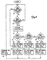
- controller 62 causes "regular" concentration batches of chemical to be mixed in mix vessel 12 in accordance with steps 102 and 104.
- controller 62 causes vacuum/pressure/vent system 36 to vent the mix vessel 12.
- Control valve V2 is then opened to allow ultra pure water to flow into mix vessel 12.
- controller 62 closes valve V2 to complete step 102.
- Controller 62 then causes vacuum/pressure/vent system 36 to draw a vacuum in mix vessel 12. After the vacuum is established, valve V1 is opened to allow concentrated HF to flow into mix vessel 12.
- controller 62 closes valve V1 to complete step 104.
- controller 62 causes vacuum/pressure/vent system 36 to pressurize mix vessel 12, and opens valve V3. The mixed batch of chemical is thereby motivated into the mix drum 14 through line 38.
- controller 62 closes valve V3 to end step 106.
- steps 100, 102, 104 and 106 are repeated to mix and transfer to mix drum 14 regular concentration batches of chemical until the mix drum is filled to the low level.
- Recirculation mode operation of system 10 is initiated by controller 62 when mix drum 14 is filled to the low level determined by sensor 55. Whenever sensor S5 indicates that the level of chemical within mix drum 14 is greater than or equal to the low level (step 100) and sensor S6 indicates that the chemical level is less than the high level (step 108), controller 62 determines the then current concentration of the chemical within the mix drum as indicated by step 110.
- controller 62 determines that the measured concentration of the chemical within drum 14 is less than or equal to the Upper Qualification Range Setpoint and greater than or equal to the Lower Qualification Range Setpoint (i.e., within the desired qualification range)
- the controller causes a regular concentration batch of chemical to be mixed in mix vessel 12 and transferred to the mix drum in the manner described above (steps 102, 104 and 106).
- controller 62 causes a "low" concentration batch of chemical to be mixed in mix vessel 12 in accordance with steps 116 and 118.
- controller 62 causes vacuum/pressure/vent system 36 to vent mix vessel 12.
- Valve V2 is then opened to allow ultra pure water to flow into mix vessel 12.
- controller 62 closes valve V2 to complete step 116.
- Vacuum/pressure/vent system 36 is then operated to draw a vacuum in the mix vessel 12. After the vacuum is established, valve V1 is opened to allow concentrated HF to flow into mix vessel 12.
- controller 62 closes valve V1 to complete step 118.
- the low concentration batch of chemical is then transferred to the mix drum 14 in accordance with step 106 described above.
- the addition of the low concentration mix batch of chemical to mix drum 14 will reduce the concentration of the chemical within the mix drum, and is done to lower the concentration to the desired concentration.
- controller 62 causes a "high" concentration batch of chemical to be mixed in mix vessel 12 in accordance with steps 122 and 124.
- controller 62 causes vacuum/pressure/vent system 36 to vent mix vessel 12.
- valve V2 is then opened to allow ultra pure water to flow into mix vessel 12.
- controller 62 closes valve V2 to complete step 122.
- vacuum/pressure/vent system 36 is then operated to draw a vacuum in the mix vessel 12. After the vacuum is established, valve V1 is opened to allow concentrated HF to flow into mix vessel 12.
- controller 62 closes valve V1 to complete step 124.
- the high concentration batch of chemical is then transferred to the mix drum 14 in accordance with step 106 described above.
- the addition of the high concentration mix batch of chemical to mix drum 14 will increase the concentration of the chemical within the mix drum, and is done to raise the concentration to the desired concentration.
Landscapes
- Physics & Mathematics (AREA)
- General Physics & Mathematics (AREA)
- Engineering & Computer Science (AREA)
- Automation & Control Theory (AREA)
- Accessories For Mixers (AREA)
- Sampling And Sample Adjustment (AREA)
- Investigating Or Analysing Biological Materials (AREA)
Applications Claiming Priority (3)
| Application Number | Priority Date | Filing Date | Title |
|---|---|---|---|
| US08/554,787 US5632960A (en) | 1995-11-07 | 1995-11-07 | Two-stage chemical mixing system |
| US554787 | 1995-11-07 | ||
| PCT/US1996/017820 WO1997017640A1 (en) | 1995-11-07 | 1996-11-07 | Two-stage chemical mixing system |
Publications (3)
| Publication Number | Publication Date |
|---|---|
| EP0864123A1 EP0864123A1 (en) | 1998-09-16 |
| EP0864123A4 EP0864123A4 (en) | 1999-01-20 |
| EP0864123B1 true EP0864123B1 (en) | 2003-05-28 |
Family
ID=24214718
Family Applications (1)
| Application Number | Title | Priority Date | Filing Date |
|---|---|---|---|
| EP96939567A Expired - Lifetime EP0864123B1 (en) | 1995-11-07 | 1996-11-07 | Two-stage chemical mixing system |
Country Status (7)
| Country | Link |
|---|---|
| US (2) | US5632960A (enExample) |
| EP (1) | EP0864123B1 (enExample) |
| JP (1) | JP2000500696A (enExample) |
| KR (1) | KR100394181B1 (enExample) |
| AT (1) | ATE241818T1 (enExample) |
| DE (1) | DE69628445T2 (enExample) |
| WO (1) | WO1997017640A1 (enExample) |
Families Citing this family (39)
| Publication number | Priority date | Publication date | Assignee | Title |
|---|---|---|---|---|
| US6065863A (en) * | 1997-04-17 | 2000-05-23 | Solvent Solutions, Inc. | System for mixing bulk windshield washer liquid for both cold and warm climates |
| US6004025A (en) * | 1997-05-16 | 1999-12-21 | Life Technologies, Inc. | Automated liquid manufacturing system |
| US6332559B1 (en) * | 1997-10-15 | 2001-12-25 | Ekolink Pty Ltd | Liquor dispensing apparatus |
| BR9800361A (pt) * | 1998-02-13 | 2000-09-26 | Renner Du Pont Tintas Automoti | Processo continuo e automatico para a produção de tintas automotivas e outros |
| US20070119816A1 (en) * | 1998-04-16 | 2007-05-31 | Urquhart Karl J | Systems and methods for reclaiming process fluids in a processing environment |
| US7980753B2 (en) | 1998-04-16 | 2011-07-19 | Air Liquide Electronics U.S. Lp | Systems and methods for managing fluids in a processing environment using a liquid ring pump and reclamation system |
| WO1999056189A1 (en) * | 1998-04-30 | 1999-11-04 | The Boc Group, Inc. | Conductivity feedback control system for slurry blending |
| TW479841U (en) * | 1998-06-17 | 2002-03-11 | United Microelectronics Corp | Polishing slurry supply apparatus |
| US6224252B1 (en) * | 1998-07-07 | 2001-05-01 | Air Products And Chemicals, Inc. | Chemical generator with controlled mixing and concentration feedback and adjustment |
| JP3728945B2 (ja) * | 1998-10-30 | 2005-12-21 | オルガノ株式会社 | フォトレジスト現像廃液からの現像液の回収再利用方法及び装置 |
| US6247838B1 (en) * | 1998-11-24 | 2001-06-19 | The Boc Group, Inc. | Method for producing a liquid mixture having a predetermined concentration of a specified component |
| US6527018B2 (en) * | 2000-06-07 | 2003-03-04 | Fuji Photo Film Co., Ltd. | Method and system for optimizing batch process of preparing solution |
| TWI298826B (en) * | 2001-02-06 | 2008-07-11 | Hirama Lab Co Ltd | Purified developer producing equipment and method |
| JP3869730B2 (ja) * | 2002-01-16 | 2007-01-17 | 株式会社平間理化研究所 | 処理液調製供給方法及び装置 |
| US20040151062A1 (en) * | 2003-01-30 | 2004-08-05 | Taiwan Semiconductor Manufacturing Co., Ltd. | Automatic chemical mixing system |
| KR100500475B1 (ko) * | 2003-11-10 | 2005-07-12 | 삼성전자주식회사 | 케미컬 혼합장치 |
| US20050146982A1 (en) * | 2003-12-31 | 2005-07-07 | Carlson Stephen J. | Quick blend module |
| KR20070041556A (ko) * | 2004-07-08 | 2007-04-18 | 트레스-아크, 인크 | 화학물 혼합용 장치와 시스템 및 방법 |
| US20060080041A1 (en) * | 2004-07-08 | 2006-04-13 | Anderson Gary R | Chemical mixing apparatus, system and method |
| US7281840B2 (en) * | 2004-07-09 | 2007-10-16 | Tres-Ark, Inc. | Chemical mixing apparatus |
| US20060196541A1 (en) * | 2005-03-04 | 2006-09-07 | David Gerken | Control of fluid conditions in bulk fluid distribution systems |
| US7810516B2 (en) * | 2005-03-04 | 2010-10-12 | Air Liquide Electronics U.S. Lp | Control of fluid conditions in bulk fluid distribution systems |
| US20090092001A1 (en) | 2005-07-27 | 2009-04-09 | Clay Hildreth | Solution making system and method |
| DE102005059177B3 (de) * | 2005-11-10 | 2007-06-28 | Vortex-Nanofluid Gmbh | Vorrichtung und Verfahren zum Herstellen von Nano-Dispersionen |
| US7743783B2 (en) * | 2006-04-04 | 2010-06-29 | Air Liquide Electronics U.S. Lp | Method and apparatus for recycling process fluids |
| US20070251585A1 (en) * | 2006-04-28 | 2007-11-01 | David Paul Edwards | Fluid distribution system |
| US8235580B2 (en) | 2006-10-12 | 2012-08-07 | Air Liquide Electronics U.S. Lp | Reclaim function for semiconductor processing systems |
| WO2008139417A2 (en) * | 2007-05-14 | 2008-11-20 | L'air Liquide-Societe Anonyme Pour L'etude Et L'exploitation Des Procedes Georges Claude | Systems and methods for mixing fluids |
| RU2366496C1 (ru) * | 2008-05-19 | 2009-09-10 | Открытое акционерное общество "Магнитогорский металлургический комбинат" | Способ управления усреднением сыпучих компонентов |
| WO2012128603A1 (fr) * | 2011-03-22 | 2012-09-27 | Aouad Salah Mohammed | Dispositif automatique et procede de preparation de solutions |
| US10544340B2 (en) | 2011-10-20 | 2020-01-28 | Henderson Products, Inc. | Brine generation system |
| US10766010B2 (en) | 2011-10-20 | 2020-09-08 | Henderson Products, Inc. | High throughput brine generating system |
| US9097388B2 (en) * | 2012-07-13 | 2015-08-04 | Intermolecular, Inc. | Effluent management, waste dilution, effluent pre-dilution, acid waste handling |
| US20160296902A1 (en) | 2016-06-17 | 2016-10-13 | Air Liquide Electronics U.S. Lp | Deterministic feedback blender |
| CA3041841A1 (en) * | 2016-11-01 | 2018-05-11 | Cms Technology, Inc. | Systems and methods for improved blending of agents in chemical applications |
| US11724236B2 (en) * | 2018-12-20 | 2023-08-15 | Xia Tai Xin Semiconductor (Qing Dao) Ltd. | System and method for fluid preparation |
| US11761582B2 (en) * | 2019-09-05 | 2023-09-19 | Dhf America, Llc | Pressure regulation system and method for a fluidic product having particles |
| EP4603226A3 (en) | 2019-11-27 | 2025-10-22 | Diversified Fluid Solutions, LLC | On-demand in-line-blending and supply of chemicals |
| KR102612978B1 (ko) * | 2022-08-02 | 2023-12-13 | 나가세 엔지니어링 서비스 코리아(주) | 혼합 시스템 |
Family Cites Families (27)
| Publication number | Priority date | Publication date | Assignee | Title |
|---|---|---|---|---|
| FR2230978A1 (en) * | 1973-05-23 | 1974-12-20 | Inst Francais Du Petrole | Fluid flow control from storage reservoir - gives precise control even when rate of flow is low |
| US3877682A (en) * | 1974-03-08 | 1975-04-15 | Mosstype Corp | Automatic chemical measuring and mixing machine |
| US3960295A (en) * | 1974-08-19 | 1976-06-01 | Vladimir Horak | Continuous liquid proportioning system |
| US4019528A (en) * | 1975-07-23 | 1977-04-26 | Anton Braun | Fluid mixing apparatus |
| US4106671A (en) * | 1975-10-31 | 1978-08-15 | Beckman Instruments, Inc. | Liquid head control system |
| DE2708422C2 (de) * | 1977-02-26 | 1979-04-05 | Jagenberg-Werke Ag, 4000 Duesseldorf | Einrichtung zur impulsweisen Abgabe sehr kleiner Flüssigkeitsmengen, insbesondere von H2O2 |
| HU178929B (en) * | 1979-07-21 | 1982-07-28 | Ganz Mueszer Muevek | Equipment for the determination of evaporation and/or precipitate |
| US4242841A (en) * | 1979-07-30 | 1981-01-06 | Ushakov Vladimir F | Apparatus for preparing and feeding an abrasive-containing suspension into the zone of action of work tools of polishing and finishing lathes |
| US4362033A (en) * | 1980-05-08 | 1982-12-07 | Dominion Textile, Inc. | Automatic mixing and cloth bleaching control |
| DE3037898A1 (de) * | 1980-10-07 | 1982-05-06 | Bruker Analytische Meßtechnik GmbH, 7512 Rheinstetten | Mischkammer |
| US4483357A (en) * | 1983-02-22 | 1984-11-20 | Globe-Union Inc. | Method for two stage in-line acid mixing |
| FR2551360B1 (fr) * | 1983-09-05 | 1986-05-16 | Martineau Sarl Expl Ets | Procede pour produire des solutions a concentrations souhaitees a partir de produits liquides et de diluant et un appareil mettant en oeuvre ce procede |
| US4523854A (en) * | 1983-11-07 | 1985-06-18 | World Color Press, Inc. | Apparatus for mixing fountain solution |
| US4580699A (en) * | 1983-12-20 | 1986-04-08 | Chem-Trend Incorporated | Proportioner |
| US4669496A (en) * | 1984-03-12 | 1987-06-02 | Figgie International Inc. | Liquid proportioner |
| US5137694A (en) * | 1985-05-08 | 1992-08-11 | Ecolab Inc. | Industrial solid detergent dispenser and cleaning system |
| US4823987A (en) * | 1986-04-28 | 1989-04-25 | Ryco Graphic Manufacturing, Inc. | Liquid mixing system and method |
| NO172266C (no) * | 1988-04-29 | 1993-06-23 | Ulstein Nor As | Fremgangsmaate og innretning for automatisk fremstilling av en blanding som bestaar av minst to stroembare bestanddeler |
| US4863277A (en) * | 1988-12-22 | 1989-09-05 | Vigoro Industries, Inc. | Automated batch blending system for liquid fertilizer |
| US5108655A (en) * | 1989-05-30 | 1992-04-28 | Electro-System, Incorporated | Foam monitoring control system |
| SE467816B (sv) * | 1990-02-19 | 1992-09-21 | Gambro Ab | System foer beredning av en vaetska avsedd foer medicinskt bruk |
| US5370269A (en) * | 1990-09-17 | 1994-12-06 | Applied Chemical Solutions | Process and apparatus for precise volumetric diluting/mixing of chemicals |
| US5148945B1 (en) * | 1990-09-17 | 1996-07-02 | Applied Chemical Solutions | Apparatus and method for the transfer and delivery of high purity chemicals |
| US5417346A (en) * | 1990-09-17 | 1995-05-23 | Applied Chemical Solutions | Process and apparatus for electronic control of the transfer and delivery of high purity chemicals |
| KR930008856B1 (ko) * | 1991-05-15 | 1993-09-16 | 금성일렉트론 주식회사 | 혼합용액의 일정비율 혼합장치 |
| US5340210A (en) * | 1992-02-25 | 1994-08-23 | Nalco Chemical Company | Apparatus for blending chemicals with a reversible multi-speed pump |
| JP3141919B2 (ja) * | 1994-10-13 | 2001-03-07 | 三菱瓦斯化学株式会社 | 薬液調合装置および方法 |
-
1995
- 1995-11-07 US US08/554,787 patent/US5632960A/en not_active Expired - Fee Related
-
1996
- 1996-11-07 WO PCT/US1996/017820 patent/WO1997017640A1/en not_active Ceased
- 1996-11-07 KR KR10-1998-0703403A patent/KR100394181B1/ko not_active Expired - Fee Related
- 1996-11-07 AT AT96939567T patent/ATE241818T1/de not_active IP Right Cessation
- 1996-11-07 JP JP9518309A patent/JP2000500696A/ja not_active Ceased
- 1996-11-07 DE DE69628445T patent/DE69628445T2/de not_active Expired - Fee Related
- 1996-11-07 EP EP96939567A patent/EP0864123B1/en not_active Expired - Lifetime
-
1997
- 1997-01-23 US US08/789,335 patent/US5874049A/en not_active Expired - Fee Related
Also Published As
| Publication number | Publication date |
|---|---|
| US5874049A (en) | 1999-02-23 |
| US5632960A (en) | 1997-05-27 |
| ATE241818T1 (de) | 2003-06-15 |
| EP0864123A1 (en) | 1998-09-16 |
| DE69628445D1 (de) | 2003-07-03 |
| DE69628445T2 (de) | 2004-01-15 |
| KR100394181B1 (ko) | 2003-12-18 |
| EP0864123A4 (en) | 1999-01-20 |
| WO1997017640A1 (en) | 1997-05-15 |
| KR19990067393A (ko) | 1999-08-16 |
| JP2000500696A (ja) | 2000-01-25 |
Similar Documents
| Publication | Publication Date | Title |
|---|---|---|
| EP0864123B1 (en) | Two-stage chemical mixing system | |
| WO1997017640A9 (en) | Two-stage chemical mixing system | |
| US5924794A (en) | Chemical blending system with titrator control | |
| EP0716879B1 (en) | Apparatus for blending chemical and diluent liquids | |
| US6146008A (en) | System for diluting ultrapure chemicals which is intended for the microelectronics industry | |
| US5490611A (en) | Process for precise volumetrio diluting/mixing of chemicals | |
| TW458806B (en) | Method and apparatus for continuously blending chemical solutions | |
| US7344298B2 (en) | Method and apparatus for blending process materials | |
| US6796703B2 (en) | Conductivity feedback control system for slurry bending | |
| US20060080041A1 (en) | Chemical mixing apparatus, system and method | |
| JP3741811B2 (ja) | アルカリ現像原液の希釈方法および希釈装置 | |
| US7281840B2 (en) | Chemical mixing apparatus | |
| JPH08108054A (ja) | 薬液調合装置および方法 | |
| EP0605095B1 (en) | Apparatus and method for preparing a developer solution | |
| US20050146982A1 (en) | Quick blend module | |
| JP3120817B2 (ja) | 現像液の自動希釈装置 | |
| US20080172141A1 (en) | Chemical Mixing Apparatus, System And Method | |
| JPH0871389A (ja) | 現像液の調整方法 | |
| JPH0724289A (ja) | 現像液調合装置及び現像液の調合方法 | |
| US20070098598A1 (en) | In-line automated fluid dilution | |
| TW202407314A (zh) | 檢量線液製造系統、測定系統及檢量線液製造方法 |
Legal Events
| Date | Code | Title | Description |
|---|---|---|---|
| PUAI | Public reference made under article 153(3) epc to a published international application that has entered the european phase |
Free format text: ORIGINAL CODE: 0009012 |
|
| 17P | Request for examination filed |
Effective date: 19980509 |
|
| AK | Designated contracting states |
Kind code of ref document: A1 Designated state(s): AT BE CH DE DK ES FI FR GB GR IE IT LI LU MC NL PT SE |
|
| A4 | Supplementary search report drawn up and despatched |
Effective date: 19981208 |
|
| AK | Designated contracting states |
Kind code of ref document: A4 Designated state(s): AT BE CH DE DK ES FI FR GB GR IE IT LI LU MC NL PT SE |
|
| 17Q | First examination report despatched |
Effective date: 20000508 |
|
| GRAG | Despatch of communication of intention to grant |
Free format text: ORIGINAL CODE: EPIDOS AGRA |
|
| GRAG | Despatch of communication of intention to grant |
Free format text: ORIGINAL CODE: EPIDOS AGRA |
|
| GRAH | Despatch of communication of intention to grant a patent |
Free format text: ORIGINAL CODE: EPIDOS IGRA |
|
| GRAH | Despatch of communication of intention to grant a patent |
Free format text: ORIGINAL CODE: EPIDOS IGRA |
|
| GRAA | (expected) grant |
Free format text: ORIGINAL CODE: 0009210 |
|
| AK | Designated contracting states |
Designated state(s): AT BE CH DE DK ES FI FR GB GR IE IT LI LU MC NL PT SE |
|
| PG25 | Lapsed in a contracting state [announced via postgrant information from national office to epo] |
Ref country code: NL Free format text: LAPSE BECAUSE OF FAILURE TO SUBMIT A TRANSLATION OF THE DESCRIPTION OR TO PAY THE FEE WITHIN THE PRESCRIBED TIME-LIMIT Effective date: 20030528 Ref country code: LI Free format text: LAPSE BECAUSE OF FAILURE TO SUBMIT A TRANSLATION OF THE DESCRIPTION OR TO PAY THE FEE WITHIN THE PRESCRIBED TIME-LIMIT Effective date: 20030528 Ref country code: IT Free format text: LAPSE BECAUSE OF FAILURE TO SUBMIT A TRANSLATION OF THE DESCRIPTION OR TO PAY THE FEE WITHIN THE PRESCRIBED TIME-LIMIT;WARNING: LAPSES OF ITALIAN PATENTS WITH EFFECTIVE DATE BEFORE 2007 MAY HAVE OCCURRED AT ANY TIME BEFORE 2007. THE CORRECT EFFECTIVE DATE MAY BE DIFFERENT FROM THE ONE RECORDED. Effective date: 20030528 Ref country code: FI Free format text: LAPSE BECAUSE OF FAILURE TO SUBMIT A TRANSLATION OF THE DESCRIPTION OR TO PAY THE FEE WITHIN THE PRESCRIBED TIME-LIMIT Effective date: 20030528 Ref country code: CH Free format text: LAPSE BECAUSE OF FAILURE TO SUBMIT A TRANSLATION OF THE DESCRIPTION OR TO PAY THE FEE WITHIN THE PRESCRIBED TIME-LIMIT Effective date: 20030528 Ref country code: BE Free format text: LAPSE BECAUSE OF FAILURE TO SUBMIT A TRANSLATION OF THE DESCRIPTION OR TO PAY THE FEE WITHIN THE PRESCRIBED TIME-LIMIT Effective date: 20030528 Ref country code: AT Free format text: LAPSE BECAUSE OF FAILURE TO SUBMIT A TRANSLATION OF THE DESCRIPTION OR TO PAY THE FEE WITHIN THE PRESCRIBED TIME-LIMIT Effective date: 20030528 |
|
| REG | Reference to a national code |
Ref country code: GB Ref legal event code: FG4D |
|
| REG | Reference to a national code |
Ref country code: CH Ref legal event code: EP |
|
| REG | Reference to a national code |
Ref country code: IE Ref legal event code: FG4D |
|
| REF | Corresponds to: |
Ref document number: 69628445 Country of ref document: DE Date of ref document: 20030703 Kind code of ref document: P |
|
| PG25 | Lapsed in a contracting state [announced via postgrant information from national office to epo] |
Ref country code: SE Free format text: LAPSE BECAUSE OF FAILURE TO SUBMIT A TRANSLATION OF THE DESCRIPTION OR TO PAY THE FEE WITHIN THE PRESCRIBED TIME-LIMIT Effective date: 20030828 Ref country code: PT Free format text: LAPSE BECAUSE OF FAILURE TO SUBMIT A TRANSLATION OF THE DESCRIPTION OR TO PAY THE FEE WITHIN THE PRESCRIBED TIME-LIMIT Effective date: 20030828 Ref country code: GR Free format text: LAPSE BECAUSE OF FAILURE TO SUBMIT A TRANSLATION OF THE DESCRIPTION OR TO PAY THE FEE WITHIN THE PRESCRIBED TIME-LIMIT Effective date: 20030828 Ref country code: DK Free format text: LAPSE BECAUSE OF FAILURE TO SUBMIT A TRANSLATION OF THE DESCRIPTION OR TO PAY THE FEE WITHIN THE PRESCRIBED TIME-LIMIT Effective date: 20030828 |
|
| PG25 | Lapsed in a contracting state [announced via postgrant information from national office to epo] |
Ref country code: ES Free format text: LAPSE BECAUSE OF FAILURE TO SUBMIT A TRANSLATION OF THE DESCRIPTION OR TO PAY THE FEE WITHIN THE PRESCRIBED TIME-LIMIT Effective date: 20030908 |
|
| NLV1 | Nl: lapsed or annulled due to failure to fulfill the requirements of art. 29p and 29m of the patents act | ||
| PG25 | Lapsed in a contracting state [announced via postgrant information from national office to epo] |
Ref country code: LU Free format text: LAPSE BECAUSE OF NON-PAYMENT OF DUE FEES Effective date: 20031107 Ref country code: IE Free format text: LAPSE BECAUSE OF NON-PAYMENT OF DUE FEES Effective date: 20031107 Ref country code: GB Free format text: LAPSE BECAUSE OF NON-PAYMENT OF DUE FEES Effective date: 20031107 |
|
| PGFP | Annual fee paid to national office [announced via postgrant information from national office to epo] |
Ref country code: FR Payment date: 20031119 Year of fee payment: 8 |
|
| ET | Fr: translation filed | ||
| PG25 | Lapsed in a contracting state [announced via postgrant information from national office to epo] |
Ref country code: MC Free format text: LAPSE BECAUSE OF NON-PAYMENT OF DUE FEES Effective date: 20031130 |
|
| REG | Reference to a national code |
Ref country code: CH Ref legal event code: PL |
|
| PGFP | Annual fee paid to national office [announced via postgrant information from national office to epo] |
Ref country code: DE Payment date: 20031231 Year of fee payment: 8 |
|
| PLBE | No opposition filed within time limit |
Free format text: ORIGINAL CODE: 0009261 |
|
| STAA | Information on the status of an ep patent application or granted ep patent |
Free format text: STATUS: NO OPPOSITION FILED WITHIN TIME LIMIT |
|
| 26N | No opposition filed |
Effective date: 20040302 |
|
| GBPC | Gb: european patent ceased through non-payment of renewal fee |
Effective date: 20031107 |
|
| REG | Reference to a national code |
Ref country code: IE Ref legal event code: MM4A |
|
| PG25 | Lapsed in a contracting state [announced via postgrant information from national office to epo] |
Ref country code: DE Free format text: LAPSE BECAUSE OF NON-PAYMENT OF DUE FEES Effective date: 20050601 |
|
| PG25 | Lapsed in a contracting state [announced via postgrant information from national office to epo] |
Ref country code: FR Free format text: LAPSE BECAUSE OF NON-PAYMENT OF DUE FEES Effective date: 20050729 |
|
| REG | Reference to a national code |
Ref country code: FR Ref legal event code: ST |
|
| REG | Reference to a national code |
Ref country code: FR Ref legal event code: TP |