EP0861310B1 - Methode und vorrichtung zum katalytischen craken mit fluss in abwärtsrichtung durch einspritzung vom ausgangsstoff in einem gezielten winkel auf den konditionierten katalysator - Google Patents
Methode und vorrichtung zum katalytischen craken mit fluss in abwärtsrichtung durch einspritzung vom ausgangsstoff in einem gezielten winkel auf den konditionierten katalysator Download PDFInfo
- Publication number
- EP0861310B1 EP0861310B1 EP97919105A EP97919105A EP0861310B1 EP 0861310 B1 EP0861310 B1 EP 0861310B1 EP 97919105 A EP97919105 A EP 97919105A EP 97919105 A EP97919105 A EP 97919105A EP 0861310 B1 EP0861310 B1 EP 0861310B1
- Authority
- EP
- European Patent Office
- Prior art keywords
- catalyst
- zone
- feed
- injection
- flow
- Prior art date
- Legal status (The legal status is an assumption and is not a legal conclusion. Google has not performed a legal analysis and makes no representation as to the accuracy of the status listed.)
- Expired - Lifetime
Links
- 239000003054 catalyst Substances 0.000 title claims abstract description 143
- 238000000034 method Methods 0.000 title claims abstract description 20
- 238000004523 catalytic cracking Methods 0.000 title claims abstract description 9
- 230000001143 conditioned effect Effects 0.000 title description 2
- 238000002347 injection Methods 0.000 claims abstract description 70
- 239000007924 injection Substances 0.000 claims abstract description 70
- 230000003750 conditioning effect Effects 0.000 claims abstract description 24
- 230000008929 regeneration Effects 0.000 claims abstract description 22
- 238000011069 regeneration method Methods 0.000 claims abstract description 22
- 230000008569 process Effects 0.000 claims abstract description 18
- 238000005243 fluidization Methods 0.000 claims abstract description 13
- 239000004215 Carbon black (E152) Substances 0.000 claims abstract description 10
- 229930195733 hydrocarbon Natural products 0.000 claims abstract description 10
- 150000002430 hydrocarbons Chemical class 0.000 claims abstract description 10
- 238000011144 upstream manufacturing Methods 0.000 claims abstract description 6
- 230000001105 regulatory effect Effects 0.000 claims abstract description 4
- 239000003208 petroleum Substances 0.000 claims abstract 2
- 238000007493 shaping process Methods 0.000 claims description 27
- 238000006243 chemical reaction Methods 0.000 claims description 20
- 238000005336 cracking Methods 0.000 claims description 10
- 239000000203 mixture Substances 0.000 claims description 5
- 230000005484 gravity Effects 0.000 claims description 4
- 238000000926 separation method Methods 0.000 claims description 4
- 239000007789 gas Substances 0.000 description 16
- 230000003197 catalytic effect Effects 0.000 description 3
- 239000000571 coke Substances 0.000 description 3
- 239000012530 fluid Substances 0.000 description 3
- 238000004519 manufacturing process Methods 0.000 description 3
- 238000004806 packaging method and process Methods 0.000 description 3
- 239000007787 solid Substances 0.000 description 3
- -1 C 3 olefins Chemical class 0.000 description 2
- QVGXLLKOCUKJST-UHFFFAOYSA-N atomic oxygen Chemical compound [O] QVGXLLKOCUKJST-UHFFFAOYSA-N 0.000 description 2
- 238000000889 atomisation Methods 0.000 description 2
- 230000004907 flux Effects 0.000 description 2
- 239000001257 hydrogen Substances 0.000 description 2
- 229910052739 hydrogen Inorganic materials 0.000 description 2
- 238000002156 mixing Methods 0.000 description 2
- 210000000056 organ Anatomy 0.000 description 2
- 239000001301 oxygen Substances 0.000 description 2
- 229910052760 oxygen Inorganic materials 0.000 description 2
- 239000002245 particle Substances 0.000 description 2
- 239000000523 sample Substances 0.000 description 2
- UFHFLCQGNIYNRP-UHFFFAOYSA-N Hydrogen Chemical compound [H][H] UFHFLCQGNIYNRP-UHFFFAOYSA-N 0.000 description 1
- 240000008042 Zea mays Species 0.000 description 1
- 238000013459 approach Methods 0.000 description 1
- 230000008901 benefit Effects 0.000 description 1
- 230000015572 biosynthetic process Effects 0.000 description 1
- 238000009529 body temperature measurement Methods 0.000 description 1
- 230000008859 change Effects 0.000 description 1
- 238000002485 combustion reaction Methods 0.000 description 1
- 230000000052 comparative effect Effects 0.000 description 1
- 150000001875 compounds Chemical class 0.000 description 1
- 230000003628 erosive effect Effects 0.000 description 1
- 150000002431 hydrogen Chemical class 0.000 description 1
- 238000012986 modification Methods 0.000 description 1
- 230000004048 modification Effects 0.000 description 1
- 238000005457 optimization Methods 0.000 description 1
- JTJMJGYZQZDUJJ-UHFFFAOYSA-N phencyclidine Chemical class C1CCCCN1C1(C=2C=CC=CC=2)CCCCC1 JTJMJGYZQZDUJJ-UHFFFAOYSA-N 0.000 description 1
- 230000001737 promoting effect Effects 0.000 description 1
- 238000004064 recycling Methods 0.000 description 1
- 230000009467 reduction Effects 0.000 description 1
- 239000002002 slurry Substances 0.000 description 1
- 238000003860 storage Methods 0.000 description 1
- 239000000725 suspension Substances 0.000 description 1
- 238000010408 sweeping Methods 0.000 description 1
- 238000012546 transfer Methods 0.000 description 1
- 230000001052 transient effect Effects 0.000 description 1
- 238000009834 vaporization Methods 0.000 description 1
- 230000008016 vaporization Effects 0.000 description 1
- 239000013598 vector Substances 0.000 description 1
- 210000003462 vein Anatomy 0.000 description 1
- XLYOFNOQVPJJNP-UHFFFAOYSA-N water Chemical compound O XLYOFNOQVPJJNP-UHFFFAOYSA-N 0.000 description 1
Images
Classifications
-
- C—CHEMISTRY; METALLURGY
- C10—PETROLEUM, GAS OR COKE INDUSTRIES; TECHNICAL GASES CONTAINING CARBON MONOXIDE; FUELS; LUBRICANTS; PEAT
- C10G—CRACKING HYDROCARBON OILS; PRODUCTION OF LIQUID HYDROCARBON MIXTURES, e.g. BY DESTRUCTIVE HYDROGENATION, OLIGOMERISATION, POLYMERISATION; RECOVERY OF HYDROCARBON OILS FROM OIL-SHALE, OIL-SAND, OR GASES; REFINING MIXTURES MAINLY CONSISTING OF HYDROCARBONS; REFORMING OF NAPHTHA; MINERAL WAXES
- C10G11/00—Catalytic cracking, in the absence of hydrogen, of hydrocarbon oils
- C10G11/14—Catalytic cracking, in the absence of hydrogen, of hydrocarbon oils with preheated moving solid catalysts
- C10G11/18—Catalytic cracking, in the absence of hydrogen, of hydrocarbon oils with preheated moving solid catalysts according to the "fluidised-bed" technique
- C10G11/187—Controlling or regulating
-
- C—CHEMISTRY; METALLURGY
- C10—PETROLEUM, GAS OR COKE INDUSTRIES; TECHNICAL GASES CONTAINING CARBON MONOXIDE; FUELS; LUBRICANTS; PEAT
- C10G—CRACKING HYDROCARBON OILS; PRODUCTION OF LIQUID HYDROCARBON MIXTURES, e.g. BY DESTRUCTIVE HYDROGENATION, OLIGOMERISATION, POLYMERISATION; RECOVERY OF HYDROCARBON OILS FROM OIL-SHALE, OIL-SAND, OR GASES; REFINING MIXTURES MAINLY CONSISTING OF HYDROCARBONS; REFORMING OF NAPHTHA; MINERAL WAXES
- C10G11/00—Catalytic cracking, in the absence of hydrogen, of hydrocarbon oils
- C10G11/14—Catalytic cracking, in the absence of hydrogen, of hydrocarbon oils with preheated moving solid catalysts
- C10G11/18—Catalytic cracking, in the absence of hydrogen, of hydrocarbon oils with preheated moving solid catalysts according to the "fluidised-bed" technique
Definitions
- the invention relates to a process for catalytic cracking in a fluid bed (FCC) of a hydrocarbon charge in a reaction zone where the charge circulates from top to low (in English dropper).
- FCC fluid bed
- Patent application EP-A-0479645 describes a downflow reactor or dropper in which the load is supplied in a co-current direction the catalyst flow. This flows from a dense phase.
- the area of dense phase catalyst can be a dense fluidized bed storage area located between the particle regenerator and the entrance to the droppers. In these conditions, the density of the gas-solid suspension can be controlled.
- a another patent application EP-A-0663434 describes a dropper supplied with a catalyst from a conditioning zone of the fluidized bed catalyst which is connected to a coker catalyst regenerator. The packaging area includes elsewhere a gas disengagement zone.
- US Pat. No. 4,919,898 describes the formation of a curtain falling from the catalyst from rectangular openings coming from a bed pressurized by steam. This bed therefore regulates the pressure difference between the enclosure containing the pressurized bed and a chamber for mixing the catalyst and the charge downstream of the bed. This patent further describes the injection of the charge in the direction of the valve forming the curtain.
- US Patent 5,296,131 further describes a downwardly flowing catalyst curtain of annular shape.
- the charge is injected downward at least in part through a radial opening under the seat of a valve type valve of frustoconical shape, pressed against the upper part of the reactor.
- patent application EP-A-0 209 442 which describes the presence of a valve downstream of a first fluidization ring which disturbs the fluidization conditions until defluidization leading to obtaining a density corresponding to a bulk bed.
- the object of the invention is to remedy the drawbacks of the prior art.
- the invention relates to a catalytic cracking process in fluidized bed of an oil charge in lighter effluents in a cracked zone catalytic comprising a reaction zone or dropper in which introduces regenerated catalyst at an upper end called the injection zone coming from at least one regeneration zone, the catalyst is shaped by means of a shaping member having a restriction, it is brought into contact the catalyst with the charge, we form a mixture flowing down from catalyst and charge, and at least the majority of the charge is vaporized in said injection zone, we crack said charge to obtain lighter effluents, we separates effluent from spent catalyst in a separation zone at the end lower, the effluent is recovered and the spent catalyst is recycled in the regeneration, the process being characterized in that the catalyst is run off regenerated from the regeneration zone in a conditioning zone catalyst in a dense fluidized bed upstream of the injection zone comprising a gas disengagement zone, the speed of fluidization by a fluidizing gas being between 0.1 and 30 cm / s, a flow of catalyst flowing
- the flow of catalyst flowing by gravity through the restriction with a variable or constant passage section is, as a general rule, between 200 and 20,000 kg / m 2 .s and preferably between 1,000 and 10,000 kg / m 2 .s, an excellent range of values between 4,000 and 6,000 kg / m 2 .s.
- the charge can be injected by a plurality of injectors arranged all around the wall of the injection area at an angle less than or equal to 30 degrees from the horizontal and preferably at an angle of 5 to 25 degrees.
- the injection angle ⁇ is determined so that the result of the vectors taking into account the momentum of the charge and the amount of movement of the catalyst is substantially horizontal, for example more or less ten degrees around the horizontal.
- the catalyst mass ratio on load in the injection area can be between 5 and 20, preferably between 10 and 18.
- the speed of the gravity-flowing catalyst by the restriction can be from 0.1 to 20 m / s and advantageously from 0.5 to 5 m / s, while the speed atomized charge droplets is usually between 50 and 100 m / s and preferably 70 to 90 m / s.
- the flow rate of catalyst in the injection zone can be adjusted by means of a valve with variable opening which can be that according to the first variant, or a valve with variable opening arranged on the introduction line of the regenerated catalyst and from the regenerator to the conditioning area.
- This valve is also slaved to a temperature sensor at the output of the dropper.
- the catalyst conditioning zone can have a catalyst gas disengagement zone above the level dense fluidized bed, between a third and a half of the total height of the conditioning area.
- the injection zone of the reaction zone is generally sized to receive a given mass of catalyst such as the residence time in this zone is usually between 0.02 s and 0.5 s and preferably between 0.03 s and 0.1 s.
- the catalyst can be one of those known to those skilled in the art, for example those cited in US Patent 5,296,131.
- the member for introducing the hydrocarbon charge can be any member well known to those skilled in the art allowing the introduction of a hydrocarbon charge, preferably in the form of droplets preferably having a mean diameter. less than 5x10 -4 meter (m) and advantageously less than 1x10 -4 (m). It is preferable that the hydrocarbon charge is introduced so as to form fine droplets distributed homogeneously at the level of the introduction zone.
- An auxiliary fluid called atomization promoting the production of fine droplets can also be introduced with the hydrocarbon charge.
- This auxiliary fluid will usually be a gas such as steam, or a gas relatively rich in hydrogen or hydrogenated compounds from other units of the refinery.
- the atomization is generally carried out outside the reaction zone.
- injectors are usually arranged at the periphery of the injection area, under the catalyst shaping member and their end is located in at minus a plane substantially perpendicular to the axis of the injection zone or of the dropper.
- the distance of these injectors, counted from the theoretical impact points of the jets load on the axis of the injection zone (or reaction zone), at the point lowest of the catalyst forming member is at most equal to 2 times the diameter of the injection area.
- this distance can be 0.5 to 1 times the diameter of the zone injection.
- the invention also relates to a catalytic cracking unit with a descending reactor. or dropper to catalytically crack a hydrocarbon charge in the presence of a cracking catalyst and to produce an effluent of light products and coked cracking catalyst.
- Unit includes organ with restriction for the shaping of the catalyst upstream of the dropper, a supply of charge communicating with an injection chamber at the top of the dropper and bringing the charge into contact with the shaped catalyst, a effluent separation enclosure for the coked catalyst at the bottom of the dropper and at least one coke catalyst regeneration enclosure communicating with the separation enclosure and a catalyst supply line regenerated connecting the regeneration enclosure to the catalyst shaping member, said unit being characterized in that it comprises an enclosure of conditioning of the regenerated catalyst in a dense fluidized bed connected between the regenerator and the catalyst shaping member, said enclosure comprising fluidization means and having a catalyst disengagement zone from the gas, of suitable volume at the top of said enclosure, which communicates by a pressure equalization line with the upper part of the containment regeneration, and in that
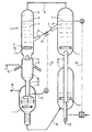
- a device 1 for catalytic cracking in a known fluidized bed known in itself essentially comprises a dropper (descending reactor) 13 supplied with its upper part by catalyst conditioned in an enclosure of conditioning 2.
- This enclosure is supplied with catalyst by a line 3 oblique, coming from a regeneration zone which in this case contains two regenerators 4 and 17 in fluidized bed, superimposed.
- the dropper is fed in its upper part by a load introduced by injectors 12 and vaporized in contact with the hot regenerated catalyst (approximately 780 ° C).
- the effluents are separated from the catalyst in a stripper 14 known per se, discharged by a line 15 while the catalyst once stripped by water vapor by example and containing coke is recycled in the first regenerator 17 by a recycling line 16.
- the catalyst partially regenerated, in the presence of a gas containing oxygen is raised in the second regenerator 4 by a lift 25, where it undergoes a second combustion in the presence of an oxygen-containing gas.
- cyclones or means of fluidization in the separator or regenerators which are well known to those skilled in the art, and which do not are not shown in the figure for the sake of simplification.
- the regenerated and hot catalyst from the second zone of regeneration in dense fluidized phase is introduced by gravity through line 3 inclined in the packaging enclosure 2 in a dense fluidized bed upstream of the dropper 13.
- a fluidization ring 5 supplies a fluidization gas 5a which may be steam, the lower part of the enclosure for conditioning the catalyst at a speed of 10 cm / s.
- the catalyst then has a density, for example between 550 and 800 kg / m 3 and typically 600 kg / m 3 .
- the catalyst conditioning chamber 2 is dimensioned so as to present in its upper part a zone 8 for disengagement of the gas from the catalyst, located above the arrival of line 3 and of height between the third and a quarter of the total height of the conditioning enclosure.
- Line 9 pressure balancing connects the disengagement zone to the upper part of the second regenerator.
- level 7 of the fluidized bed in the second controlled regenerator by a level probe 23 and controlled by a regulator 24 to the air flow of rise (lift) of the catalyst corresponds substantially to that 6 of the fluidized bed in the conditioning enclosure.
- the device Downstream of the conditioning enclosure 2, the device comprises an injection chamber 10 of diameter at least equal to that of the dropper, at the inlet of which a flow control valve 11 or shaping valve of a curtain of falling catalyst lets escape, by its annular section of opening or restriction, a catalyst flow of about 800 kg / m 2 .s.
- This valve can have a fixed central part or insert which determines with the wall from the injection zone, the cross section of the catalyst flow determined in combination with another flow control valve 19 on the intake line catalyst 3.
- the curtain shaping valve can comprise a movable central part connected to a rod, according to patent FR 2631857, this rod being protected from the catalyst by a sheath containing a sweeping gas. Said movable central part of the valve determines with its seat a section of adequate annular passage for a given flow rate of catalyst delivered by the valve 19 and therefore an appropriate flow.
- the injection chamber generally has a larger diameter than that of the restriction (the largest diameter of the annular curtain of catalyst formed) so that the charge injector tips do not intercept the catalyst curtain.
- the charge after being atomized outside the device, is injected by a plurality of injectors 12 disposed at the periphery, on a plane substantially perpendicular to the axis of the dropper and whose jet of charge droplets is directed towards said axis at an injection angle close to 25 degrees of angle under the valve 11, against the current of the curtain falling from the catalyst, which allows it to break.
- the distance of the injectors, counted from the theoretical impact points of the jets load on the axis of the injection chamber (or of the dropper), at the lowest point of the shaping member of the catalyst curtain is at most equal to 2 times the diameter of the injection enclosure and preferably between 0.5 and 1 times that diameter.
- This distance of the injectors relative to the valve 11 prevents on the one hand the erosion of the valve and on the other hand the recirculation zones above the injectors, the catalyst and / or charge.
- This dropper can have a diameter smaller than that of the enclosure injection.
- the cracked effluents are collected after stripping with steam using the line 15 and the catalyst is recycled to the first regenerator 17.
- the flow control valve 19 is generally controlled by a line 22 to a temperature measurement 20 given by a probe 21 arranged at the lower end of the dropper.
- the unit is generally started by closing the flow restriction 11 variable or by closing an all or nothing valve not shown in the figure, placed for example below the member 11, when the latter, with a fixed central part, determines a constant passage section of catalyst.
- the part of the catalyst shaping member opposite the load injected can have a concave shape and thus determine an area of containment for the vaporization thereof capable of improving the selectivity of the cracking reaction.
- the distance along the axis of the charge injectors from the insert (most bottom) is 0.5 times the diameter of the injection chamber.
Landscapes
- Chemical & Material Sciences (AREA)
- Oil, Petroleum & Natural Gas (AREA)
- Engineering & Computer Science (AREA)
- Chemical Kinetics & Catalysis (AREA)
- General Chemical & Material Sciences (AREA)
- Organic Chemistry (AREA)
- Production Of Liquid Hydrocarbon Mixture For Refining Petroleum (AREA)
- Devices And Processes Conducted In The Presence Of Fluids And Solid Particles (AREA)
- Catalysts (AREA)
Claims (16)
- Verfahren zum katalytischen Kracken im Wirbelbett einer Erdölcharge in leichtere Abströme in einer katalytischen Krackzone, die eine Reaktionszone (13) oder sog. Dropper umfasst, in die man an einem oberen Injektionszone (10) genannten Ende regenerierten Katalysator einführt, der aus wenigstens einer Regenerationszone (4) stammt, man den regenerierten Katalysator aus der Regenerationszone (4) in eine Konditionierungszone (2) für den Katalysator im dichten Wirbelbett vor der eine Gasfreisetzungszone (8) umfassenden Injektionszone strömen lässt, wobei die Geschwindigkeit der Fluidisierung durch ein Fluidisierungsgas zwischen 0,1 und 30 cm/s liegt, man einen Katalysatorstrom steuert, der durch Schwerkraft in die Injektionszone strömt, den Katalysator vermittels eines Formgebungsorgans (11), das eine Verengung aufweist, formt, den Katalysator mit der Charge kontaktiert, ein Gemisch bildet, das Katalysator und Charge nach unten strömen lässt und man wenigstens den überwiegenden Teil der Charge in der Injektionszone verdampft, diese Charge krackt, um leichtere Abströme zu erhalten, die Abströme des verbrauchten Katalysators in einer Separatorzone (14) am unteren Ende trennt, die Abströme gewinnt und den verbrauchten Katalysator in die Regenerationszone rezykliert, Verfahren, dadurch gekennzeichnet, dass man die Charge in die Injektionszone unterhalb des Formgebungsorgans für den Katalysator im Gegenstrom zur Strömungsrichtung des Katalysators und unter einem festgelegten Injektionswinkel als Funktion der Größe der Bewegung der Charge und der Bewegungsgröße des Katalysators injiziert und man das die verdampfte Charge enthaltende Gemisch in die Reaktionszone strömen lässt.
- Verfahren nach Anspruch 1, bei dem das Massenverhältnis c/o (Katalysator zu Charge) in der Injektionszone zwischen 5 und 20 und bevorzugt zwischen 10 und 18 beträgt.
- Verfahren nach Anspruch 1 oder 2, bei dem die Geschwindigkeit des Katalysators in der Injektionszone zwischen 0,1 und 20 m/s und bevorzugt zwischen 0,5 und 5 m/s und die Geschwindigkeit der zerstäubten Charge zwischen 50 und 100 m/s und bevorzugt zwischen 70 und 90 m/s beträgt.
- Verfahren nach Anspruch 1 bis 3, bei dem man einen Katalysatorvorhang vermittels des Organs zur Formgebung des Katalysators realisiert, welches einen festen fest mit der Wand der Injektionszone verbundenen Teil und einen beweglichen mittigen Teil umfasst, der mit diesem festen Teil zusammenwirkt, um diese Verengung, die einen variablen Durchlassquerschnitt hat, zu erzeugen.
- Verfahren nach einem der Ansprüche 1 bis 4, bei dem man den Katalysatorstrom für einen gegebenen Durchsatz in der Injektionszone einstellt bzw. steuert, indem man den Durchlassquerschnitt zwischen dem festen Teil und dem beweglichen Teil dieses Formgebungsorgans des Katalysators variieren lässt.
- Verfahren nach einem der Ansprüche 1 bis 3, bei dem man durch Schwerkraft den Katalysator durch das Formgebungsorgan für den Katalysator strömen lässt, welches diese Verengung umfasst, die über einen konstanten Durchlassquerschnitt verfügt.
- Verfahren nach einem der Ansprüche 1 bis 6, bei dem man quer durch den Durchlassquerschnitt einen Katalysatorstrom fließen lässt, der zwischen 200 und 20 000 kg/m2.s, bevorzugt zwischen 1 000 und 10 000 kg/m2.s ,ausmacht.
- Verfahren nach einem der Ansprüche 1 bis 7, bei dem die Verweilzeit der Injektionszone der Charge zwischen 0,02 und 0,5 s beträgt.
- Verfahren nach einem der Ansprüche 1 bis 8, bei dem die Konditionierungszone für den Katalysator die Gasfreisetzungszone (8) oberhalb des Wirbelbetts umfasst, deren Niveau sich im wesentlichen um das dieses Wirbelbetts in der Regenerationszone erstreckt und von einer Höhe zwischen dem Viertel und der Hälfte der Gesamthöhe der Konditionierungszone des Katalysators ist und bei dem man die Drücke in der Konditionierungszone und in der Regenerationszone vermittels einer Ausgleichsleitung (9) ausgleicht, welche die Freisetzungszone im oberen Teil der Regenerationszone anschließt.
- Verfahren nach einem der Ansprüche 1 bis 9, bei dem dieser Injektionswinkel für die Charge kleiner oder gleich 30 Grad ist und der Winkel null ausgeschlossen ist und bevorzugt zwischen 5 und 25 Grad liegt.
- Verfahren nach einem der Ansprüche 1 bis 10, bei dem die Injektionszone einen Durchmesser größer oder gleich dem der Reaktionszone hat.
- Verfahren nach einem der Ansprüche 1 bis 11, bei dem der Abstand der Injektoren für die Charge, berechnet ausgehend von den theoretischen Auftreffpunkten der Chargenstrahlen auf die Achse der Injektionszone (oder der Reaktionszone) zum untersten Punkt des Formgebungsorgans des Katalysators höchstens gleich dem zweifachen Durchmesser der Injektionszone ist.
- Katalytische Krackeinheit mit einer Reaktionszone, wo die Charge von oben nach unten fließt oder tropft, einem sog. Dropper (13), um katalytisch eine kohlenwasserstoffhaltige Charge in Anwesenheit eines Krackkatalysators zu kracken und um einen Abstrom für leichte Produkte und für verkokten Krackkatalysator zu erzeugen, mit wenigstens einem Regenerationsgefäß (4) für den verkokten Katalysator, einem Konditionierungsgefäß (2) für den regenerierten Katalysator im dichten Wirbelbett, verbunden mit dem Regenerator und einem Organ (11) zur Formgebung des Katalysators, wobei das Konditionierungsgefäß Mittel (5) zur Fluidisierung und eine Katalysatorfreisetzungszone (8) für Gas umfasst, und zwar von einem geeigneten Volumen im oberen Teil dieses Gefäßes, das über eine Druckausgleichsleitung (9) mit dem oberen Teil des Regenerierungsgefäßes in Verbindung steht und dieses Organ (11) eine Verengung zur Formgebung des Katalysators vor dem Dropper aufweist, eine Chargenspeisung, die mit einer Injektionskammer (10) im oberen Teil des Droppers in Verbindung steht und die Charge mit dem geformten Katalysator in Kontakt setzt, einem Trenngefäß (14) für die Abströme des verkokten Katalysators im unteren Teil des Droppers, die mit dem Regenerationsgefäß in Verbindung steht, wobei diese Einheit dadurch gekennzeichnet ist, dass die Injektionskammer (10) für die Charge eine Vielzahl von Injektoren (12) umfasst, welche die Charge im Gegenstrom zur Strömung des Katalysators unter dem Organ zur Formgebung des Katalysators gegen die Achse dieser Kammer unter einem Winkel kleiner oder gleich 30 Grad, bezogen auf die Horizontale, einführt.
- Einheit nach Anspruch 13, bei der das Organ zur Formgebung des Katalysators einen festen fest mit der Wand der Injektionszone verbundenen Teil und einen mittigen beweglichen Teil umfasst, der mit diesem festen Teil zusammenwirkt, um diese Verengung zu erzeugen und einen Katalysatorvorhang zu bilden.
- Einheit nach Anspruch 13, bei der das Formgebungsorgan für den Katalysator eine Verengung von einem konstanten Katalysatordurchlassquerschnitt umfasst.
- Einheit nach einem der Ansprüche 13 bis 15, bei der der Abstand der Chargeninjektoren, berechnet ausgehend von den theoretischen Auftreffpunkten der Charge auf die Injektionsachse (oder Reaktionszone) zum tiefsten Punkt des Katalysatorformgebungsorgans höchstens gleich dem zweifachen Durchmesser der Injektionszone ist.
Applications Claiming Priority (3)
| Application Number | Priority Date | Filing Date | Title |
|---|---|---|---|
| FR9611379A FR2753454B1 (fr) | 1996-09-18 | 1996-09-18 | Procede et dispositif de craquage catalytique descendant mettant en oeuvre l'injection d'une charge sous un angle adequat sur un catalyseur conditionne |
| FR9611379 | 1996-09-18 | ||
| PCT/FR1997/001630 WO1998012280A1 (fr) | 1996-09-18 | 1997-09-16 | Procede et dispositif de craquage catalytique descendant mettant en oeuvre l'injection d'une charge sous un angle adequat sur un catalyseur conditionne |
Publications (2)
| Publication Number | Publication Date |
|---|---|
| EP0861310A1 EP0861310A1 (de) | 1998-09-02 |
| EP0861310B1 true EP0861310B1 (de) | 2001-12-12 |
Family
ID=9495851
Family Applications (1)
| Application Number | Title | Priority Date | Filing Date |
|---|---|---|---|
| EP97919105A Expired - Lifetime EP0861310B1 (de) | 1996-09-18 | 1997-09-16 | Methode und vorrichtung zum katalytischen craken mit fluss in abwärtsrichtung durch einspritzung vom ausgangsstoff in einem gezielten winkel auf den konditionierten katalysator |
Country Status (13)
| Country | Link |
|---|---|
| US (1) | US6099720A (de) |
| EP (1) | EP0861310B1 (de) |
| JP (1) | JP4281026B2 (de) |
| KR (1) | KR100493753B1 (de) |
| CN (1) | CN1134528C (de) |
| AT (1) | ATE210712T1 (de) |
| CA (1) | CA2236296C (de) |
| DE (1) | DE69709050T2 (de) |
| ES (1) | ES2169860T3 (de) |
| FR (1) | FR2753454B1 (de) |
| ID (1) | ID18268A (de) |
| MX (1) | MX9803790A (de) |
| WO (1) | WO1998012280A1 (de) |
Cited By (1)
| Publication number | Priority date | Publication date | Assignee | Title |
|---|---|---|---|---|
| EP2385094A1 (de) | 2010-05-06 | 2011-11-09 | IFP Energies nouvelles | Katkrackverfahren mit Recycling eines ölhaltigen Verschnittes, der vor dem Abschnitt der Gasabscheidung zur Maximierung der Propylenproduktion entnommen wird |
Families Citing this family (13)
| Publication number | Priority date | Publication date | Assignee | Title |
|---|---|---|---|---|
| BR0101433B1 (pt) * | 2001-04-10 | 2011-02-22 | método e dispositivo de entrada multi-funcional para reator tubular de fluxo descendente. | |
| EP1392796A2 (de) * | 2001-06-08 | 2004-03-03 | Albemarle Netherlands B.V. | Fluidbett katalytisches crackverfahren |
| US7087154B2 (en) * | 2002-12-30 | 2006-08-08 | Petroleo Brasileiro S.A. - Petrobras | Apparatus and process for downflow fluid catalytic cracking |
| CN1332742C (zh) * | 2004-05-14 | 2007-08-22 | 中国石油化工股份有限公司 | 催化裂化装置催化剂/助剂补充方法 |
| US20080011644A1 (en) * | 2006-07-13 | 2008-01-17 | Dean Christopher F | Ancillary cracking of heavy oils in conjuction with FCC unit operations |
| US20080011645A1 (en) * | 2006-07-13 | 2008-01-17 | Dean Christopher F | Ancillary cracking of paraffinic naphtha in conjuction with FCC unit operations |
| US7758817B2 (en) * | 2006-08-09 | 2010-07-20 | Uop Llc | Device for contacting high contaminated feedstocks with catalyst in an FCC unit |
| EP2300573B1 (de) * | 2008-06-04 | 2018-10-10 | Inbicon A/S | Vorrichtungen und verfahren zum austragen von vorbehandelter biomasse von bereichen höheren drucks in bereiche niedrigeren drucks |
| US9458394B2 (en) | 2011-07-27 | 2016-10-04 | Saudi Arabian Oil Company | Fluidized catalytic cracking of paraffinic naphtha in a downflow reactor |
| JP5823911B2 (ja) * | 2012-04-27 | 2015-11-25 | Jx日鉱日石エネルギー株式会社 | 流動接触分解装置における原料と触媒を混合する混合装置 |
| CN108726507B (zh) * | 2017-04-21 | 2020-11-13 | 山东大展纳米材料有限公司 | 一种单级连续化制备碳纳米管的装置及方法 |
| KR102763934B1 (ko) * | 2018-07-16 | 2025-02-06 | 아넬로테크, 인코퍼레이티드 | 유동층 촉매성 열분해 반응기 내로의 바이오매스 주입 |
| CN117654409A (zh) * | 2023-11-03 | 2024-03-08 | 佛山市瑞重机械设备有限公司 | 一种纳米气相二氧化硅表面改性生产装置及其生产方法 |
Family Cites Families (9)
| Publication number | Priority date | Publication date | Assignee | Title |
|---|---|---|---|---|
| US2668755A (en) * | 1948-11-23 | 1954-02-09 | Kellogg M W Co | Plug-type control valve for fluidized catalyst conversion system |
| JPS624784A (ja) * | 1985-07-16 | 1987-01-10 | コンパニ−・フランセ−ズ・ド・ラフイナ−ジユ | 炭化水素仕込物の接触クラツキングのための方法および装置の改良 |
| US4919898A (en) * | 1987-08-11 | 1990-04-24 | Stone & Webster Engineering Corp. | Particulate solids cracking apparatus |
| US4985136A (en) * | 1987-11-05 | 1991-01-15 | Bartholic David B | Ultra-short contact time fluidized catalytic cracking process |
| FR2631857B1 (fr) * | 1988-05-24 | 1990-09-14 | Inst Francais Du Petrole | Reacteur a lit fluidise entraine comprenant un moyen de regulation du flux de particules solides et son utilisation dans un procede de craquage catalytique |
| FR2667609B1 (fr) * | 1990-10-03 | 1993-07-16 | Inst Francais Du Petrole | Procede et dispositif de craquage catalytique en lit fluide a courant descendant. |
| FR2683743B1 (fr) * | 1991-11-14 | 1994-02-11 | Institut Francais Petrole | Procede et dispositif d'echange thermique de particules solides pour double regeneration en craquage catalytique. |
| US5296131A (en) * | 1992-12-02 | 1994-03-22 | Mobil Oil Corporation | Process for short contact time cracking |
| FR2715163B1 (fr) * | 1994-01-18 | 1996-04-05 | Total Raffinage Distribution | Procédé de craquage catalytique en lit fluidisé d'une charge d'hydrocarbures, notamment d'une charge à forte teneur en composés azotés basiques. |
-
1996
- 1996-09-18 FR FR9611379A patent/FR2753454B1/fr not_active Expired - Fee Related
-
1997
- 1997-09-15 ID IDP973186A patent/ID18268A/id unknown
- 1997-09-16 ES ES97919105T patent/ES2169860T3/es not_active Expired - Lifetime
- 1997-09-16 CA CA002236296A patent/CA2236296C/fr not_active Expired - Lifetime
- 1997-09-16 CN CNB97191706XA patent/CN1134528C/zh not_active Expired - Lifetime
- 1997-09-16 US US09/077,007 patent/US6099720A/en not_active Expired - Lifetime
- 1997-09-16 JP JP51434198A patent/JP4281026B2/ja not_active Expired - Lifetime
- 1997-09-16 KR KR10-1998-0703660A patent/KR100493753B1/ko not_active Expired - Lifetime
- 1997-09-16 AT AT97919105T patent/ATE210712T1/de not_active IP Right Cessation
- 1997-09-16 DE DE69709050T patent/DE69709050T2/de not_active Expired - Lifetime
- 1997-09-16 WO PCT/FR1997/001630 patent/WO1998012280A1/fr not_active Ceased
- 1997-09-16 EP EP97919105A patent/EP0861310B1/de not_active Expired - Lifetime
-
1998
- 1998-05-13 MX MX9803790A patent/MX9803790A/es unknown
Cited By (1)
| Publication number | Priority date | Publication date | Assignee | Title |
|---|---|---|---|---|
| EP2385094A1 (de) | 2010-05-06 | 2011-11-09 | IFP Energies nouvelles | Katkrackverfahren mit Recycling eines ölhaltigen Verschnittes, der vor dem Abschnitt der Gasabscheidung zur Maximierung der Propylenproduktion entnommen wird |
Also Published As
| Publication number | Publication date |
|---|---|
| DE69709050D1 (de) | 2002-01-24 |
| ES2169860T3 (es) | 2002-07-16 |
| FR2753454A1 (fr) | 1998-03-20 |
| JP2001503080A (ja) | 2001-03-06 |
| KR19990067633A (ko) | 1999-08-25 |
| CN1208432A (zh) | 1999-02-17 |
| MX9803790A (es) | 1998-09-30 |
| KR100493753B1 (ko) | 2005-09-02 |
| CA2236296C (fr) | 2007-01-16 |
| CN1134528C (zh) | 2004-01-14 |
| ATE210712T1 (de) | 2001-12-15 |
| EP0861310A1 (de) | 1998-09-02 |
| DE69709050T2 (de) | 2002-05-02 |
| WO1998012280A1 (fr) | 1998-03-26 |
| FR2753454B1 (fr) | 1999-06-04 |
| JP4281026B2 (ja) | 2009-06-17 |
| CA2236296A1 (fr) | 1998-03-26 |
| US6099720A (en) | 2000-08-08 |
| ID18268A (id) | 1998-03-19 |
Similar Documents
| Publication | Publication Date | Title |
|---|---|---|
| EP0861310B1 (de) | Methode und vorrichtung zum katalytischen craken mit fluss in abwärtsrichtung durch einspritzung vom ausgangsstoff in einem gezielten winkel auf den konditionierten katalysator | |
| EP1800742B1 (de) | Reaktor mit zwei fluidisierbaren Reaktionsstufen und einem integrierten Gas/Feststofftrennsystem | |
| EP0208609B1 (de) | Verfahren und Einrichtung für das katalytische Kracken von Kohlenwasserstoffen mit Kontrolle der Reaktionstemperatur | |
| EP1413622B1 (de) | Verfahren zur flüssigen katalytischen Spaltung in zwei integrierten, mit unterschiedlicher Strenge, bei einer Abkühlungszone gefolgten Spaltenzonen | |
| EP0479645B1 (de) | Fluidisiertes katalytisches Krackverfahren und -apparat mit Abwärtsfliessung | |
| EP1242569B1 (de) | Verfahren und vorrichtung zur katalytischen spaltung mit aufwärts- und abwärtsbetriebenen parallelen reaktoren | |
| EP0323297B1 (de) | Wirbelschichtverfahren zur Kohlenwasserstoffumwandlung | |
| EP0485259B1 (de) | Verfahren und Einrichtung für Homogenisierung in ein röhrenformige Kohlenwasserstoff-Krackreaktor mit Wirbelbett von feste Teilchen, von das Gemisch von diese Teilchen und die zu behandeln Kohlenwasserstoffen | |
| EP1170355B1 (de) | Verfahren und Einrichtung zum Cracken von Kohlenwasserstoffen in zwei aufeinanderfolgenden Reaktionstufen | |
| FR2576906A1 (fr) | Procede et dispositif d'injection de catalyseur dans un procede de craquage catalytique a l'etat fluide, notamment de charges lourdes | |
| EP0184517B1 (de) | Verfahren und Anlagen für das katalytische Kracken von Kohlenwasserstoffeinsätzen | |
| EP0226483B1 (de) | Verfahren und Vorrichtung für die katalytische Spaltung eines mit wenig aktiven Festteilchen vorbehandelten Kohlenwasserstoffeinsatzes | |
| EP0874880B1 (de) | Fluidkatalytisch krackverfahren und -einrichtung fur kohlenwasserstoffeinsätze | |
| EP2366760A1 (de) | Verfahren zum katalytischen Cracken mit feiner Kontrolle des Restgehalts an Koks auf dem Katalysator nach Regenerierung | |
| EP0291408B1 (de) | Dampfspaltungsverfahren in einer Wirbelschicht-Reaktionszone | |
| US6346219B1 (en) | FCC feed injector with closure plug | |
| EP0573316B1 (de) | Verfahren und Einrichtung zum katalytischen Kracken in zwei aufeinanderfolgenden Reaktionszonen | |
| FR2770225A1 (fr) | Procede et dispositif de vaporisation selective des charges d'hydrocarbures en craquage catalytique | |
| CA1337340C (fr) | Reacteur a lit fluidise entraine comprenant un moyen de regulation du flux de particules solides et son utilisation dans un procede de craquage catalytique | |
| EP1275425A1 (de) | Interne Vorrichtung zur Trennung eines Gemisches mit mindestens einer Gasphase und einer Flüssigphase | |
| EP0536054B1 (de) | Verbesserungen an Vorrichtungen für das katalytische Wirbelschichtkracken von Kohlenwasserstoffeinsätzen | |
| FR2628117A2 (fr) | Procede de craquage catalytique | |
| EP0265347A1 (de) | Verfahren und Vorrichtung für die katalytische Wirbelschichtspaltung von Kohlenwasserstoffeinsätzen | |
| EP4601781A1 (de) | Gas-feststoff-gleichstrom-abwärtsfluss-wirbelschichtreaktor mit homogenem fluss |
Legal Events
| Date | Code | Title | Description |
|---|---|---|---|
| PUAI | Public reference made under article 153(3) epc to a published international application that has entered the european phase |
Free format text: ORIGINAL CODE: 0009012 |
|
| AK | Designated contracting states |
Kind code of ref document: A1 Designated state(s): AT BE CH DE DK ES FI FR GB GR IE IT LI LU MC NL PT SE |
|
| 17P | Request for examination filed |
Effective date: 19980928 |
|
| 17Q | First examination report despatched |
Effective date: 19990506 |
|
| GRAG | Despatch of communication of intention to grant |
Free format text: ORIGINAL CODE: EPIDOS AGRA |
|
| GRAG | Despatch of communication of intention to grant |
Free format text: ORIGINAL CODE: EPIDOS AGRA |
|
| GRAH | Despatch of communication of intention to grant a patent |
Free format text: ORIGINAL CODE: EPIDOS IGRA |
|
| GRAH | Despatch of communication of intention to grant a patent |
Free format text: ORIGINAL CODE: EPIDOS IGRA |
|
| GRAA | (expected) grant |
Free format text: ORIGINAL CODE: 0009210 |
|
| AK | Designated contracting states |
Kind code of ref document: B1 Designated state(s): AT BE CH DE DK ES FI FR GB GR IE IT LI LU MC NL PT SE |
|
| PG25 | Lapsed in a contracting state [announced via postgrant information from national office to epo] |
Ref country code: IE Free format text: LAPSE BECAUSE OF FAILURE TO SUBMIT A TRANSLATION OF THE DESCRIPTION OR TO PAY THE FEE WITHIN THE PRESCRIBED TIME-LIMIT Effective date: 20011212 Ref country code: GR Free format text: LAPSE BECAUSE OF FAILURE TO SUBMIT A TRANSLATION OF THE DESCRIPTION OR TO PAY THE FEE WITHIN THE PRESCRIBED TIME-LIMIT Effective date: 20011212 Ref country code: FI Free format text: LAPSE BECAUSE OF FAILURE TO SUBMIT A TRANSLATION OF THE DESCRIPTION OR TO PAY THE FEE WITHIN THE PRESCRIBED TIME-LIMIT Effective date: 20011212 Ref country code: AT Free format text: LAPSE BECAUSE OF FAILURE TO SUBMIT A TRANSLATION OF THE DESCRIPTION OR TO PAY THE FEE WITHIN THE PRESCRIBED TIME-LIMIT Effective date: 20011212 |
|
| REF | Corresponds to: |
Ref document number: 210712 Country of ref document: AT Date of ref document: 20011215 Kind code of ref document: T |
|
| REG | Reference to a national code |
Ref country code: CH Ref legal event code: EP |
|
| REG | Reference to a national code |
Ref country code: GB Ref legal event code: IF02 |
|
| REG | Reference to a national code |
Ref country code: IE Ref legal event code: FG4D Free format text: FRENCH |
|
| REF | Corresponds to: |
Ref document number: 69709050 Country of ref document: DE Date of ref document: 20020124 |
|
| PG25 | Lapsed in a contracting state [announced via postgrant information from national office to epo] |
Ref country code: SE Free format text: LAPSE BECAUSE OF FAILURE TO SUBMIT A TRANSLATION OF THE DESCRIPTION OR TO PAY THE FEE WITHIN THE PRESCRIBED TIME-LIMIT Effective date: 20020312 Ref country code: PT Free format text: LAPSE BECAUSE OF FAILURE TO SUBMIT A TRANSLATION OF THE DESCRIPTION OR TO PAY THE FEE WITHIN THE PRESCRIBED TIME-LIMIT Effective date: 20020312 Ref country code: DK Free format text: LAPSE BECAUSE OF FAILURE TO SUBMIT A TRANSLATION OF THE DESCRIPTION OR TO PAY THE FEE WITHIN THE PRESCRIBED TIME-LIMIT Effective date: 20020312 |
|
| GBT | Gb: translation of ep patent filed (gb section 77(6)(a)/1977) |
Effective date: 20020307 |
|
| REG | Reference to a national code |
Ref country code: ES Ref legal event code: FG2A Ref document number: 2169860 Country of ref document: ES Kind code of ref document: T3 |
|
| REG | Reference to a national code |
Ref country code: IE Ref legal event code: FD4D |
|
| PG25 | Lapsed in a contracting state [announced via postgrant information from national office to epo] |
Ref country code: LU Free format text: LAPSE BECAUSE OF NON-PAYMENT OF DUE FEES Effective date: 20020916 |
|
| PG25 | Lapsed in a contracting state [announced via postgrant information from national office to epo] |
Ref country code: LI Free format text: LAPSE BECAUSE OF NON-PAYMENT OF DUE FEES Effective date: 20020930 Ref country code: CH Free format text: LAPSE BECAUSE OF NON-PAYMENT OF DUE FEES Effective date: 20020930 |
|
| PLBE | No opposition filed within time limit |
Free format text: ORIGINAL CODE: 0009261 |
|
| STAA | Information on the status of an ep patent application or granted ep patent |
Free format text: STATUS: NO OPPOSITION FILED WITHIN TIME LIMIT |
|
| 26N | No opposition filed | ||
| PG25 | Lapsed in a contracting state [announced via postgrant information from national office to epo] |
Ref country code: MC Free format text: LAPSE BECAUSE OF NON-PAYMENT OF DUE FEES Effective date: 20030401 |
|
| REG | Reference to a national code |
Ref country code: CH Ref legal event code: PL |
|
| REG | Reference to a national code |
Ref country code: FR Ref legal event code: CD |
|
| REG | Reference to a national code |
Ref country code: DE Ref legal event code: R081 Ref document number: 69709050 Country of ref document: DE Owner name: IFP ENERGIES NOUVELLES, FR Free format text: FORMER OWNER: INSTITUT FRANCAIS DU PETROLE, RUEIL-MALMAISON, HAUTS-DE-SEINE, FR Effective date: 20110331 |
|
| REG | Reference to a national code |
Ref country code: FR Ref legal event code: PLFP Year of fee payment: 20 |
|
| PGFP | Annual fee paid to national office [announced via postgrant information from national office to epo] |
Ref country code: GB Payment date: 20160926 Year of fee payment: 20 Ref country code: NL Payment date: 20160919 Year of fee payment: 20 |
|
| PGFP | Annual fee paid to national office [announced via postgrant information from national office to epo] |
Ref country code: FR Payment date: 20160922 Year of fee payment: 20 |
|
| PGFP | Annual fee paid to national office [announced via postgrant information from national office to epo] |
Ref country code: BE Payment date: 20160919 Year of fee payment: 20 Ref country code: ES Payment date: 20160923 Year of fee payment: 20 |
|
| PGFP | Annual fee paid to national office [announced via postgrant information from national office to epo] |
Ref country code: DE Payment date: 20160930 Year of fee payment: 20 |
|
| PGFP | Annual fee paid to national office [announced via postgrant information from national office to epo] |
Ref country code: IT Payment date: 20160930 Year of fee payment: 20 |
|
| REG | Reference to a national code |
Ref country code: DE Ref legal event code: R071 Ref document number: 69709050 Country of ref document: DE |
|
| REG | Reference to a national code |
Ref country code: NL Ref legal event code: MK Effective date: 20170915 |
|
| REG | Reference to a national code |
Ref country code: GB Ref legal event code: PE20 Expiry date: 20170915 |
|
| PG25 | Lapsed in a contracting state [announced via postgrant information from national office to epo] |
Ref country code: GB Free format text: LAPSE BECAUSE OF EXPIRATION OF PROTECTION Effective date: 20170915 |
|
| REG | Reference to a national code |
Ref country code: BE Ref legal event code: MK Effective date: 20170916 |
|
| REG | Reference to a national code |
Ref country code: ES Ref legal event code: FD2A Effective date: 20180508 |
|
| PG25 | Lapsed in a contracting state [announced via postgrant information from national office to epo] |
Ref country code: ES Free format text: LAPSE BECAUSE OF EXPIRATION OF PROTECTION Effective date: 20170917 |