EP0860992B1 - Television receiver with a scan converter and corresponding method - Google Patents
Television receiver with a scan converter and corresponding method Download PDFInfo
- Publication number
- EP0860992B1 EP0860992B1 EP98301268A EP98301268A EP0860992B1 EP 0860992 B1 EP0860992 B1 EP 0860992B1 EP 98301268 A EP98301268 A EP 98301268A EP 98301268 A EP98301268 A EP 98301268A EP 0860992 B1 EP0860992 B1 EP 0860992B1
- Authority
- EP
- European Patent Office
- Prior art keywords
- video signal
- signal
- scanning
- format
- line
- Prior art date
- Legal status (The legal status is an assumption and is not a legal conclusion. Google has not performed a legal analysis and makes no representation as to the accuracy of the status listed.)
- Expired - Lifetime
Links
Images


Classifications
-
- H—ELECTRICITY
- H04—ELECTRIC COMMUNICATION TECHNIQUE
- H04N—PICTORIAL COMMUNICATION, e.g. TELEVISION
- H04N7/00—Television systems
- H04N7/01—Conversion of standards, e.g. involving analogue television standards or digital television standards processed at pixel level
- H04N7/0117—Conversion of standards, e.g. involving analogue television standards or digital television standards processed at pixel level involving conversion of the spatial resolution of the incoming video signal
- H04N7/012—Conversion between an interlaced and a progressive signal
-
- H—ELECTRICITY
- H04—ELECTRIC COMMUNICATION TECHNIQUE
- H04N—PICTORIAL COMMUNICATION, e.g. TELEVISION
- H04N5/00—Details of television systems
- H04N5/44—Receiver circuitry for the reception of television signals according to analogue transmission standards
- H04N5/46—Receiver circuitry for the reception of television signals according to analogue transmission standards for receiving on more than one standard at will
Definitions
- the present invention relates to the field of receivers for receiving mixed television broadcast signals of interlace scanning system signals and progressive scanning system signals.
- Digital broadcasting is becoming more common.
- 1994 for example, the US started a multiple channel satellite digital broadcasting service, and similar services were started in 1996 in Japan and Europe.
- the use of digital video equipment is also advancing in packaged media systems including Digital Video Disks (DVDs) and Digital Video Cassettes (DVCs).
- DVDs Digital Video Disks
- DVCs Digital Video Cassettes
- ATV Advanced Television
- 4 interlace scanning system video formats 4 interlace scanning system video formats
- 14 progressive scanning system video formats 4 interlace scanning system video formats
- the progressive scanning system which has good compatibility with personal computers, is given more importance.
- a receiver of the prior art for the progressive scanning system which is capable of receiving such broadcasts converts input video signals of the interlace scanning system to signals of the progressive scanning system, and outputs only video signals of the progressive scanning system from the output terminal of the receiver.
- the receiver When video signals of the progressive scanning system are input, the receiver outputs the video signals in unmodified form, i.e., without converting them.
- a receiver of the prior art for the interlace scanning system which is capable of receiving mixed broadcast signals, converts input video signals of the progressive scanning system to signals of the interlace scanning system, and outputs only video signals of the interlace scanning system from the output terminal of the receiver.
- the receiver When video signals of the interlace scanning system are input, the receiver outputs the video, signals in an unmodified form. i.e., without converting them.
- receivers of the prior art are capable of outputting signals in only a single output format.
- Fig. 12 shows an example of a receiver of this type.
- a block diagram of major parts of the receiver is combined with a television set 62.
- the receiver When the receiver receives mixed broadcast signals containing progressive scanning system signals (hereafter referred to as the p signal) and interlace scanning system signals (hereafter referred to as the i signal), the video signals are input through a video signal input terminal 59.
- a p-i scan converter 60 the major component of the receiver, has the function of converting the p signal to the i signal.
- an i video signal output terminal 61 of the receiver for outputting the i signal
- an external input terminal 63 of the television set 62 are connected.
- An external input terminal 64 of the television set 62 and the video signal input terminal 59 of the receiver are also connected.
- External input terminals 63 and 64 are optionally provided in the television set 62.
- the p-i scan converter 60 converts the p signal to an i signal if the video signal input to the receiver is the p signal, and the video signal converted to the i signal is output from the external input terminal 63 of the television set 62 via the i video signal output terminal 61.
- the p-i scan converter 60 does not operate if the input video signal is the i signal.
- a broadcast signal is the i signal, that signal is directly input to the television set 62 because the external input terminal 64 of the television set 62 and the video signal input terminal 59 are connected.
- the user desirably switches the external input terminals 63 and 64 of the television set every time the broadcasting system is switched if both the p signal and i signal are broadcast.
- the external input terminals may be expected to be switched every 10-sec in a commercial film.
- a monitor, television set, video tape recorder, and other equipment which may be connected to the receiver, have their own switchover function, and accordingly a variety of switching systems exist for the various external input signals. If more than two pieces of external equipment are connected, operation may become even more complicated.
- EP-A-0743788 shows an automatic image scanning format converter which automatically switches between formats to provide a single output of a consistent format regardless of the input format.
- the present invention provides a method for processing a video signal which may be at any time in one of a plurality of different line-scanning formats, said method comprising the steps of:
- the present invention also provides a receiver for receiving a video signal which may be at any time in one of at least a first line-scanning format and a second line-scanning format, said receiver comprising:
- a receiver of the present invention is therefore capable of receiving mixed video broadcast signals having a plurality of different formats, converting received video signals into video signals having a format different from that of the received signals, and outputting both the converted signals and the unconnected received video signals.
- the receiver of an embodiment of the present invention is further capable of receiving mixed video broadcast signals in a plurality of different formats, converting the received video signals into video signals having a plurality of different formats from that of the received video signals, and outputting both the received video signals and a plurality of converted video signals .
- the user may be able to connect a television set compatible with either the interlace scanning system or the progressive scanning system, to a corresponding output terminal for interlace scanning video signals or an output terminal for progressive scanning video signals provided on the receiver. This allows the user to watch television without being conscious of the switching between the different broadcasting systems even if programs are broadcast in both the progressive scanning system and the interlace scanning system.
- Fig. 1 is a block diagram of a receiver in accordance with a first exemplary embodiment of the present invention.
- Fig. 2 is a block diagram of an i-p scan converter of a receiver in accordance with a second exemplary embodiment of the present invention.
- Fig. 3 explains the operation of the i-p scan converter of the receiver in accordance with the second exemplary embodiment of the present invention.
- Fig. 4 is a block diagram of an i-p scan converter of a receiver in accordance with a third exemplary embodiment of the present invention.
- Fig. 5 explains the operation of the i-p scan converter of the receiver in accordance with the third exemplary embodiment of the present invention.
- Fig. 6 is a block diagram of an i-p scan converter of a receiver in accordance with a fourth exemplary embodiment of the present invention.
- Fig. 7 explains the operation of the i-p scan converter of the receiver in accordance with the fourth exemplary embodiment of the present invention.
- Fig. 8 is a block diagram of an i-p scan converter of a receiver in accordance with a fifth exemplary embodiment of the present invention.
- Fig. 9 is a block diagram of a p-i scan converter of a receiver in accordance with a sixth exemplary embodiment of the present invention.
- Fig. 10 is a block diagram of a receiver in accordance with a seventh exemplary embodiment of the present invention.
- Fig. 11 is a block diagram of a selector in a seventh exemplary embodiment of the present invention.
- Fig. 12 explains the operation of a receiver of the prior art.
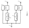
- a receiver in a first exemplary embodiment of the present invention is explained with reference to Fig. 1.
- the receiver of the first exemplary embodiment comprises a video signal input terminal 1 which receives the video signal of the interlace scanning system (hereafter referred to as the i video signal) or the video signal of the progressive scanning system (hereafter referred to as the p video signal), a p video signal output terminal 2 for outputting the signal selected by a switching circuit 6, and an i video signal output terminal 3 for outputting the signal selected by a switching circuit 7.
- the receiver is further configured with an i-p scan converter 4, a p-i scan converter 5, a switching circuit 6, and a switching circuit 7.
- the video signal input to the video signal input terminal 1 is supplied to the i-p scan converter 4, p-i scan converter 5, switching circuit 6, and switching circuit 7.
- the switching circuit 6 also receives the output signal of the i-p scan converter 4, and the switching circuit 7 also receives the output signal of the p-i scan converter 5.
- a television set is designed to be exclusive to the i signal
- the television set is connected to the i video signal output terminal 3 of the receiver.
- a television set designed to be exclusive to the p signal is connected to the p video signal output terminal 2 of the receiver.
- the video signal encoded by MPEG2, or other format before transmission, is decoded by a decoder (not illustrated).
- the decoded video signal is input to the video signal input terminal 1 of the receiver.
- This video signal as described above, contains both the i video signal and the p video signal on a time base.
- the i-p scan converter 4 converts the i video signal to the p video signal, and outputs the converted p video signal to the switching circuit 6.
- the switching circuit 6 selects the converted p video signal, and outputs the converted p video signal to the p video signal output terminal 2.
- the p-i scan converter 5 ceases to operate, and the switching circuit 7 selects the input video signal from the i video signal input terminal 1 to output the i video signal to the i video signal output terminal 3.
- video signals in both formats are simultaneously output from the respective p video signal output terminal 2 and i video signal output terminal 3.
- signals may be recordable on a VHS video tape recorder while being viewed as high picture quality p video signal images by connecting the p video signal output terminal 2 to a television set designed to receive the p video signal, and the i video signal output terminal 3 to a VHS video tape recorder.
- the p-i scan converter 5 converts the p signal into the i signal, and outputs the i video signal.
- the switching circuit 7 selects the converted i video signal, and outputs the converted i video signal to the i video signal output terminal 3.
- the i-p scan converter 4 ceases to operate, and the switching circuit 6 selects the input video image from the video signal input terminal 1 and outputs the p video signal to the p video signal output terminal 2.
- the receiver of this exemplary embodiment by providing a switching function, enables the elimination of switching operations irrespective of whether a television set which receives broadcast signals containing both the i video signal and p video signal is exclusive to the i signal or p signal.
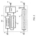
- FIG. 2 A block diagram of an i-p scan converter 204 of a receiver in a second exemplary embodiment of the present invention is explained with reference to Figs. 2 and 3.
- the receiver in the second exemplary embodiment comprises an i video signal input terminal 8 for receiving the i video signal, an i horizontal/vertical synchronizing pulse input terminal 9 for receiving the horizontal synchronizing pulse and vertical synchronizing pulse of the interlace scanning system.
- the receiver also has a p video signal output terminal 10, and a p horizontal/vertical synchronizing pulse output terminal 11 for outputting the horizontal synchronizing pulse and vertical synchronizing pulse of the progressive scanning system.
- This exemplary embodiment employs the i-p scan converter 204 comprising a line memory for time compression 12, a line memory for delay 13, a switching circuit 14, and a double-speed timing generator for progressive scanning signal 15 (hereafter referred to as the p signal double-speed timing generator).
- a scanning period of the p signal is a half (1/2) the scanning period of the i signal. Therefore, the i video signal input from the i video signal input terminal 8 is input to the line memory for time compression 12. Video data stored in the line memory for time compression 12 is compressed by half (1/2) the time base for each horizontal scanning period, and output to the switching circuit 14.
- the line memory for delay 13 then receives the output of the line memory for time compression 12 which is compressed by half (1/2) the time base, delays the line memory output by half (1/2) the horizontal scanning period, and outputs the delayed line memory output to the switching circuit 14. Accordingly, the output signal of the line memory for time compression 12 and the output signal of the line memory for delay 12 are shifted by half (1/2) the horizontal scanning period with respect to each other.
- the switching circuit 14 switches and alternately outputs these two signals, which are mutually shifted by half (1/2) the horizontal scanning period, as required.
- the p signal is composed in this way to output composed p video signal from the p video signal output terminal 10.
- the p signal double-speed timing generator 15 generates a p horizontal synchronizing pulse and p vertical synchronizing pulse by reducing the period of the i horizontal synchronizing pulse and i vertical synchronizing pulse, input through the i horizontal/vertical synchronizing input terminal 9, by half (1/2).
- the generated signal is output to a timing signal output terminal 200 for use as a timing signal in the i-p scan converter.
- the generated signal is output to the p horizontal/vertical synchronizing pulse output terminal 11.
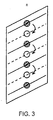
- Fig. 3 shows an image of a screen when interpolation is executed for generating the i signal and p signal.
- a certain field (n field) of i signal the video signal of one horizontal scanning line of the i signal is re-scanned before the next scanning line of the i signal. This rescanned signal is used as an interpolation signal for generating the p signal.
- the second exemplary embodiment thus offers a more inexpensive receiver employing the i-p scan converter.
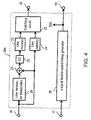
- FIG. 4 A block diagram of an i-p scan converter 304 in a third exemplary embodiment of the present invention is explained with reference to Figs. 4 and 5.
- the receiver of the third exemplary embodiment comprises an i video signal input terminal 16, i horizontal/vertical synchronizing pulse input terminal 17, p video signal output terminal 18, and p horizontal/vertical synchronizing pulse output terminal 19.
- This exemplary embodiment employs the i-p scan converter 304 comprising a line memory for interpolation 20, adder 21, divider 22, line memory 23, line memory 24, switching circuit 25, and p signal double-speed timing generator 26.
- the i video signal input from the i video signal input terminal 16 is input to the line memory for interpolation 20 and also to the adder 21 and the line memory 24.
- the input i video signal is delayed for one horizontal scanning period in the line memory for interpolation 20.
- the adder 21 adds this delayed video signal and the original i video signal.
- the divider 22 then reduces the output level of the adder 21 by half (1/2), and the divided signal is output to the line memory 23.
- This signal stored in the line memory 23 (this is an interpolation video signal) and the original video signal stored in the line memory 24 are converted to double speed on the time base, shifted from each other by half (1/2) the horizontal scanning period, and output to the switching circuit from respective line memories 23 and 24.
- the switching circuit 25 alternately switches and outputs these two signals to the p video signal output terminal 18. In this way, the i video signal is converted to a p video signal.
- the p signal double-speed timing generator 26 reduces, by half (1/2), the period of the i horizontal synchronizing pulse and i vertical synchronizing pulse, input through the i horizontal/vertical synchronizing pulse input terminal 17, to generate the p horizontal synchronizing pulse and p vertical synchronizing pulse.
- the generated synchronizing signal is output to a timing signal output terminal 300 for use as a timing signal in the i-p converter.
- the generated synchronizing signal is output to the p horizontal/vertical synchronizing pulse output terminal 19.
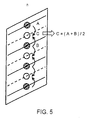
- Fig. 5 shows an image of a screen when interpolation is executed for generating the p signal from the i signal.
- a mean value of a video signal on a scanning line A and a video signal on a scanning line B is calculated. This calculated value is used as a video image on a line C which is an interpolation line for the p signal.
- the third exemplary embodiment thus offers a more inexpensive receiver employing the i-p scan converter.
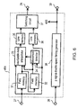
- FIG. 6 A block diagram of an i-p scan converter 404 of a receiver in accordance with a fourth exemplary embodiment of the present invention is explained with reference to Figs. 6 and 7.
- the receiver of the fourth exemplary embodiment comprises an i video signal input terminal 27, i horizontal/vertical synchronizing pulse input terminal 28, p video signal output terminal 29, and p horizontal/vertical synchronizing pulse output terminal 30.
- This exemplary embodiment employs the i-p scan converter 404 comprising a field memory 31, field memory 32, interfield/in-field interpolator 33, movement detector 34, line memory 35, line memory 36, switching circuit 37, and p signal double-speed timing generator 38.
- the i video signal input from the i video signal input terminal 27 is simultaneously supplied to the field memory 31, interfield/in-field interpolator 33, movement detector 34, and line memory 36.
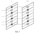
- the i video signal is delayed by one field in the field memory 31 to create one frame of the p video signal as an interpolation video signal for the original i video signal. This is shown in Fig. 7.
- in-field interpolation namely the averaging process of adjacent scanning lines, as shown in Fig. 5, is executed.
- the movement detector 34 detects an area of movement by comparing the field memory 32, the video signal delayed for 2 fields by the field memory 32, and the original i video signal. Based on this movement detection signal, the interfield/in-field interpolator 33 which receives the original i video signal, the output signal of the field memory 31, and the output signal of the field memory 32, executes interfield interpolation for still pictures, and in-field interpolation for moving picture areas.
- the line memory 35 which receives the output signal of the interfield/in-field interpolator 33, the line memory 36 which receives the original i video signal, and the switching circuit 37 which switches the output between the output of the line memory 35 and the line memory 36, operate in the same way as the line memory 23, line memory 24, and the switching circuit 25 in Fig. 4 to output the p video signal to the p video signal output terminal 29.
- the p signal double-speed timing generator 38 receives the i horizontal synchronizing pulse and i vertical synchronizing pulse from the i horizontal/vertical synchronizing pulse input terminal 28, and reduces the period of each pulse by half to generate the p horizontal synchronizing pulse and p vertical synchronizing pulse.
- the generated synchronizing signal is output to a timing output terminal 400, and is also used as a timing signal in the i-p scan converter. At the same time, the generated synchronizing signal is output to the p horizontal/vertical synchronizing pulse output terminal 30.
- the receiver which employs the i-p scan converter in the fourth exemplary embodiment, reduces the side effect in the secondary exemplary embodiment, which is that the vertical resolution of still pictures may not be improved by rescanning the same scanning line, and that flickering of scanning lines is noticeable.
- the i-p scan converter in this exemplary embodiment may also improve a remaining problem in the third exemplary embodiment, which is that vertical resolution of still pictures may not be improved by the process of averaging adjacent scanning lines and lower vertical resolution for moving pictures.
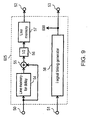
- FIG. 8 A block diagram of an i- p scan converter 504 of a receiver in a fifth exemplary embodiment of the present invention is explained with reference to Fig. 8.
- the receiver in the fifth exemplary embodiment comprises an i video signal input terminal 39, i horizontal/vertical synchronizing pulse input terminal 40, p video signal output terminal 41, and p horizontal/vertical synchronizing pulse output terminal 42.
- This exemplary embodiment employs the i-p scan converter 504 comprising an interpolation line memory 43, adder 44, divider 45, line memory 46, line memory 47, switching circuit 48, and p signal double-speed timing generator 49.
- the receiver in this exemplary embodiment reduces the signal level of the interpolated video signal to improve apparent deterioration in vertical resolution due to characteristics of display devices, such as CRTs.
- the configuration shown in Fig. 8 is basically the same as Fig. 4. The difference is that the divider 45 reduces the video signal level within a range of 0 to 1/2. Since the operation of other components are the same as that explained in Fig. 4, the explanation is not repeated.
- FIG. 9 A block diagram of a p-i scan converter of a receiver in a sixth exemplary embodiment of the present invention is explained with reference to Fig. 9.
- the receiver in the sixth exemplary embodiment comprises a p video signal input terminal 50, p horizontal/vertical synchronizing output terminal 51, i video signal output terminal 52, and i horizontal/vertical synchronizing pulse output terminal 53.
- This exemplary embodiment employs the p-i scan converter 605 comprising a line memory for delay 54, adder 55, divider 56, line memory 57, and timing generator for interlace scanning signals (i signal timing generator) 58.
- the adder 55 adds the p video signal delayed for one scanning line in the delay line memory 54 and the original p video signal, and the divider 56 calculates a mean value to generate video data for the i signal.
- the output signal of the divider 56 is doubled with respect to a time base in the line memory 57 to obtain the i video signal output.
- the i video signal is output to the i video signal output terminal 52.
- the i signal timing generator 58 receives the p horizontal synchronizing pulse and p vertical synchronizing pulse from the p horizontal/vertical synchronizing pulse input terminal 51, and doubles their period to generate the i horizontal synchronizing pulse and i vertical synchronizing pulse.
- the generated synchronizing pulses are output to a timing output terminal 600, and used as a timing signal in the p-i converter. At the same time, the generated synchronizing signal is output to the i horizontal/vertical synchronizing pulse output terminal 53.
- line memory for delay 54, adder 55, and divider 56 comprise a low-pass filter between two lines in the vertical direction of the display device. If the number of the line memory for delay 54 is increased from one to several, bandwidth characteristics in the vertical direction of the display device will become flat and display quality will be improved.
- the receiver of the seventh exemplary embodiment comprises the i-p scan converter 4, p-i scan converter 5, switching circuit 6, switching circuit 7, and a decoder 101.
- the decoder 101 decodes broadcast signals encoded by MPEG2, for example, and outputs the i video signal or p video signal in response to the format of the video signal in the received broadcast signal.
- the decoder 101 outputs i/p identifying information which informs the switching circuits 6 and 7 whether the format of the received video signal is the i video signal or p video signal to control each switching circuit to output its respective signal type.
- the video signal decoded by the decoder 101 is supplied to the i-p scan converter 4, p-i scan converter 5, switching circuit 6, and switching circuit 7.
- the signal input to the i-p scan converter 4 is scan converted from i to p, and is input to the switching circuit 6.
- the signal input to the p-i scan converter 5 is scan converted from p to i, and is output to the switching circuit 7.
- the receiver in the seventh exemplary embodiment identifies the format of the input video signal, and converts signals in the i-p scan converter 4 or p-i scan converter 5 for outputting:
- a selector in Fig. 11 may be further provided downstream of the process of Fig. 10.
- selectors 102, 103, and 104 have two input terminals and one output terminal, and the i signal is input to one input terminal, and the p signal is input to the other input terminal for selecting and outputting either the i signal or the p signal.
- selectors 102, 103, and 104 have two input terminals and one output terminal, and the i signal is input to one input terminal, and the p signal is input to the other input terminal for selecting and outputting either the i signal or the p signal.
- Four or more selectors may also be provided in place of the three selectors shown in Fig. 11.
- This configuration allows for the independent switching of selectors 102, 103, and 104, when a video image is output to more than one piece of external equipment, including monitors, television sets, and video tape recorders.
- the output of each selector can be freely determined even if each piece of external equipment is specific to the i video signal or the p video signal.
- the decoder 101 by providing the decoder 101 with the function of detecting which video signal can be successfully input to external equipment connected to the selectors 102, 103, and 104, the output of the selectors 102, 103, and 104 can be switched in response to the detected signal.
- the 1 signal (composite signal) consisting of luminance and two color difference signals are assumed to be used as both the i input signal and the p input signal. If the component signal is input as the p signal, the selectors 102, 103, and 104 may be configured to select the 1 p signal (two component signals of luminance and color difference signals) or the 3 i signals (composite).
- the user may simply desire to connect either the i video signal output terminal or the p video signal output terminal of the receiver, depending on the broadcasting format accepted by the television set.
- the receiver can also be connected to external equipment which can process only one video signal format without the need for switchover. This allows simplification of operation, even when more than two pieces of external equipment are connected.
- the exemplary embodiments of the present invention are explained with reference to receiving broadcast signals containing two types of signals, i.e., the i video signal and the p video signal.
- the present invention is not limited to these two types of signals.
- the number of circuit components including scan converters, switching circuits, input terminals and output terminals may simply be increased as desired.
- the preferred embodiments described herein are therefore illustrative and not restrictive.
Description
- The present invention relates to the field of receivers for receiving mixed television broadcast signals of interlace scanning system signals and progressive scanning system signals.
- Digital broadcasting is becoming more common. In 1994, for example, the US started a multiple channel satellite digital broadcasting service, and similar services were started in 1996 in Japan and Europe. The use of digital video equipment is also advancing in packaged media systems including Digital Video Disks (DVDs) and Digital Video Cassettes (DVCs).
- Digital broadcasting with increasingly higher image quality is also under development. For example, Advanced Television (ATV), planned in the US, is based on 18 standard video formats consisting of 4 interlace scanning system video formats and 14 progressive scanning system video formats. The progressive scanning system, which has good compatibility with personal computers, is given more importance.
- In Japan, field tests for satellite transmission of 525p signals (progressive scanning of 525 scanning lines every 1/60 sec) were carried out by the Japan television broadcast network in 1995 and 1996. Progressive scanning system signals have the same number of scanning lines as current broadcasting systems, but the resolution of moving pictures is greater, and therefore a great improvement in picture quality is expected. This system is scheduled to be commercialized in fiscal 1997.
- For digital television broadcasting, for example, 525p with high picture quality and conventional 525i (2:1 interlace scanning of 525 scanning lines every 1/30 sec, i.e., conventional NTSC) are expected to be mixed and broadcast on the same channel. A receiver of the prior art for the progressive scanning system which is capable of receiving such broadcasts converts input video signals of the interlace scanning system to signals of the progressive scanning system, and outputs only video signals of the progressive scanning system from the output terminal of the receiver. When video signals of the progressive scanning system are input, the receiver outputs the video signals in unmodified form, i.e., without converting them.
- On the other hand, a receiver of the prior art for the interlace scanning system, which is capable of receiving mixed broadcast signals, converts input video signals of the progressive scanning system to signals of the interlace scanning system, and outputs only video signals of the interlace scanning system from the output terminal of the receiver. When video signals of the interlace scanning system are input, the receiver outputs the video, signals in an unmodified form. i.e., without converting them. In other words, receivers of the prior art are capable of outputting signals in only a single output format.
- Fig. 12 shows an example of a receiver of this type. In Fig. 12, a block diagram of major parts of the receiver is combined with a
television set 62. - When the receiver receives mixed broadcast signals containing progressive scanning system signals (hereafter referred to as the p signal) and interlace scanning system signals (hereafter referred to as the i signal), the video signals are input through a video
signal input terminal 59. Ap-i scan converter 60, the major component of the receiver, has the function of converting the p signal to the i signal. - If the
television set 62 is compatible with the existing interlace scanning broadcasting, such as NTSC, an i videosignal output terminal 61 of the receiver, for outputting the i signal, and anexternal input terminal 63 of thetelevision set 62 are connected. Anexternal input terminal 64 of thetelevision set 62 and the videosignal input terminal 59 of the receiver are also connected.External input terminals television set 62. - With the above connections, the
p-i scan converter 60 converts the p signal to an i signal if the video signal input to the receiver is the p signal, and the video signal converted to the i signal is output from theexternal input terminal 63 of thetelevision set 62 via the i videosignal output terminal 61. Thep-i scan converter 60 does not operate if the input video signal is the i signal. - If a broadcast signal is the i signal, that signal is directly input to the
television set 62 because theexternal input terminal 64 of thetelevision set 62 and the videosignal input terminal 59 are connected. - With the above connections, the user desirably switches the
external input terminals - Moreover, a monitor, television set, video tape recorder, and other equipment, which may be connected to the receiver, have their own switchover function, and accordingly a variety of switching systems exist for the various external input signals. If more than two pieces of external equipment are connected, operation may become even more complicated.
- EP-A-0743788 shows an automatic image scanning format converter which automatically switches between formats to provide a single output of a consistent format regardless of the input format.
- The present invention provides a method for processing a video signal which may be at any time in one of a plurality of different line-scanning formats, said method comprising the steps of:
- converting a received video signal in a first one of said line-scanning formats into a first converted video signal having a second one of said line-scanning formats; and
- converting a received video signal in said second one of said line-scanning formats into a second converted video signal having said first one of said line-scanning formats;
- selecting and outputting a signal in said first one of said line-scanning formats by switching between the received video signal and the second converted signal; characterized by simultaneously selecting and outputting a signal in said second one of said line-scanning formats by switching between the received video signal and the first converted signal.
-
- The present invention also provides a receiver for receiving a video signal which may be at any time in one of at least a first line-scanning format and a second line-scanning format, said receiver comprising:
- first conversion means adapted to convert a received video signal in the second line-scanning format into a signal in the first line-scanning format;
- second conversion means adapted to convert a received video signal in the first line-scanning format into a signal in the second line-scanning format; and
- first switching means adapted to switch between the received video signal and the signal output from said first conversion means to provide a first switched output having said first line-scanning format; characterised by further comprising:
- second switching means adapted to switch between the received video signal and the signal output from said second conversion means to provide a second switched output having said second line-scanning format;
- wherein said receiver simultaneously outputs said first switched output as a first video signal and said second switched output as a second video signal.
-
- A receiver of the present invention is therefore capable of receiving mixed video broadcast signals having a plurality of different formats, converting received video signals into video signals having a format different from that of the received signals, and outputting both the converted signals and the unconnected received video signals.
- The receiver of an embodiment of the present invention is further capable of receiving mixed video broadcast signals in a plurality of different formats, converting the received video signals into video signals having a plurality of different formats from that of the received video signals, and outputting both the received video signals and a plurality of converted video signals .
- The user may be able to connect a television set compatible with either the interlace scanning system or the progressive scanning system, to a corresponding output terminal for interlace scanning video signals or an output terminal for progressive scanning video signals provided on the receiver. This allows the user to watch television without being conscious of the switching between the different broadcasting systems even if programs are broadcast in both the progressive scanning system and the interlace scanning system.
- Fig. 1 is a block diagram of a receiver in accordance with a first exemplary embodiment of the present invention.
- Fig. 2 is a block diagram of an i-p scan converter of a receiver in accordance with a second exemplary embodiment of the present invention.
- Fig. 3 explains the operation of the i-p scan converter of the receiver in accordance with the second exemplary embodiment of the present invention.
- Fig. 4 is a block diagram of an i-p scan converter of a receiver in accordance with a third exemplary embodiment of the present invention.
- Fig. 5 explains the operation of the i-p scan converter of the receiver in accordance with the third exemplary embodiment of the present invention.
- Fig. 6 is a block diagram of an i-p scan converter of a receiver in accordance with a fourth exemplary embodiment of the present invention.
- Fig. 7 explains the operation of the i-p scan converter of the receiver in accordance with the fourth exemplary embodiment of the present invention.
- Fig. 8 is a block diagram of an i-p scan converter of a receiver in accordance with a fifth exemplary embodiment of the present invention.
- Fig. 9 is a block diagram of a p-i scan converter of a receiver in accordance with a sixth exemplary embodiment of the present invention.
- Fig. 10 is a block diagram of a receiver in accordance with a seventh exemplary embodiment of the present invention.
- Fig. 11 is a block diagram of a selector in a seventh exemplary embodiment of the present invention.
- Fig. 12 explains the operation of a receiver of the prior art.
- A receiver in a first exemplary embodiment of the present invention is explained with reference to Fig. 1.
- The receiver of the first exemplary embodiment comprises a video
signal input terminal 1 which receives the video signal of the interlace scanning system (hereafter referred to as the i video signal) or the video signal of the progressive scanning system (hereafter referred to as the p video signal), a p videosignal output terminal 2 for outputting the signal selected by aswitching circuit 6, and an i videosignal output terminal 3 for outputting the signal selected by aswitching circuit 7. The receiver is further configured with ani-p scan converter 4, ap-i scan converter 5, aswitching circuit 6, and aswitching circuit 7. The video signal input to the videosignal input terminal 1 is supplied to thei-p scan converter 4,p-i scan converter 5, switchingcircuit 6, and switchingcircuit 7. Theswitching circuit 6 also receives the output signal of thei-p scan converter 4, and theswitching circuit 7 also receives the output signal of thep-i scan converter 5. - If a television set is designed to be exclusive to the i signal, the television set is connected to the i video
signal output terminal 3 of the receiver. On the other hand, a television set designed to be exclusive to the p signal is connected to the p videosignal output terminal 2 of the receiver. - The video signal, encoded by MPEG2, or other format before transmission, is decoded by a decoder (not illustrated). The decoded video signal is input to the video
signal input terminal 1 of the receiver. This video signal, as described above, contains both the i video signal and the p video signal on a time base. - First, when the i video signal is input, the
i-p scan converter 4 converts the i video signal to the p video signal, and outputs the converted p video signal to theswitching circuit 6. Theswitching circuit 6 selects the converted p video signal, and outputs the converted p video signal to the p videosignal output terminal 2. At this point, thep-i scan converter 5 ceases to operate, and theswitching circuit 7 selects the input video signal from the i videosignal input terminal 1 to output the i video signal to the i videosignal output terminal 3. With the above operation, video signals in both formats are simultaneously output from the respective p videosignal output terminal 2 and i videosignal output terminal 3. - For example, signals may be recordable on a VHS video tape recorder while being viewed as high picture quality p video signal images by connecting the p video
signal output terminal 2 to a television set designed to receive the p video signal, and the i videosignal output terminal 3 to a VHS video tape recorder. - Next, if the p video signal is input to the video
signal input terminal 1, thep-i scan converter 5 converts the p signal into the i signal, and outputs the i video signal. Theswitching circuit 7 selects the converted i video signal, and outputs the converted i video signal to the i videosignal output terminal 3. At this point, thei-p scan converter 4 ceases to operate, and theswitching circuit 6 selects the input video image from the videosignal input terminal 1 and outputs the p video signal to the p videosignal output terminal 2. With the above operation, video signals in both formats are simultaneously output from the respective p videosignal output terminal 2 and the i videosignal output terminal 3. - As explained above, the receiver of this exemplary embodiment, by providing a switching function, enables the elimination of switching operations irrespective of whether a television set which receives broadcast signals containing both the i video signal and p video signal is exclusive to the i signal or p signal.
- A block diagram of an
i-p scan converter 204 of a receiver in a second exemplary embodiment of the present invention is explained with reference to Figs. 2 and 3. The receiver in the second exemplary embodiment comprises an i videosignal input terminal 8 for receiving the i video signal, an i horizontal/vertical synchronizingpulse input terminal 9 for receiving the horizontal synchronizing pulse and vertical synchronizing pulse of the interlace scanning system. The receiver also has a p videosignal output terminal 10, and a p horizontal/vertical synchronizingpulse output terminal 11 for outputting the horizontal synchronizing pulse and vertical synchronizing pulse of the progressive scanning system. This exemplary embodiment employs thei-p scan converter 204 comprising a line memory fortime compression 12, a line memory fordelay 13, a switchingcircuit 14, and a double-speed timing generator for progressive scanning signal 15 (hereafter referred to as the p signal double-speed timing generator). - A scanning period of the p signal is a half (1/2) the scanning period of the i signal. Therefore, the i video signal input from the i video
signal input terminal 8 is input to the line memory fortime compression 12. Video data stored in the line memory fortime compression 12 is compressed by half (1/2) the time base for each horizontal scanning period, and output to the switchingcircuit 14. The line memory fordelay 13 then receives the output of the line memory fortime compression 12 which is compressed by half (1/2) the time base, delays the line memory output by half (1/2) the horizontal scanning period, and outputs the delayed line memory output to the switchingcircuit 14. Accordingly, the output signal of the line memory fortime compression 12 and the output signal of the line memory fordelay 12 are shifted by half (1/2) the horizontal scanning period with respect to each other. The switchingcircuit 14 switches and alternately outputs these two signals, which are mutually shifted by half (1/2) the horizontal scanning period, as required. The p signal is composed in this way to output composed p video signal from the p videosignal output terminal 10. - The p signal double-
speed timing generator 15 generates a p horizontal synchronizing pulse and p vertical synchronizing pulse by reducing the period of the i horizontal synchronizing pulse and i vertical synchronizing pulse, input through the i horizontal/verticalsynchronizing input terminal 9, by half (1/2). The generated signal is output to a timingsignal output terminal 200 for use as a timing signal in the i-p scan converter. At the same time, the generated signal is output to the p horizontal/vertical synchronizingpulse output terminal 11. - Fig. 3 shows an image of a screen when interpolation is executed for generating the i signal and p signal. In a certain field (n field) of i signal, the video signal of one horizontal scanning line of the i signal is re-scanned before the next scanning line of the i signal. This rescanned signal is used as an interpolation signal for generating the p signal.
- The second exemplary embodiment thus offers a more inexpensive receiver employing the i-p scan converter.
- A block diagram of an
i-p scan converter 304 in a third exemplary embodiment of the present invention is explained with reference to Figs. 4 and 5. The receiver of the third exemplary embodiment comprises an i videosignal input terminal 16, i horizontal/vertical synchronizingpulse input terminal 17, p videosignal output terminal 18, and p horizontal/vertical synchronizingpulse output terminal 19. This exemplary embodiment employs thei-p scan converter 304 comprising a line memory forinterpolation 20,adder 21,divider 22,line memory 23,line memory 24, switchingcircuit 25, and p signal double-speed timing generator 26. - The i video signal input from the i video
signal input terminal 16 is input to the line memory forinterpolation 20 and also to theadder 21 and theline memory 24. The input i video signal is delayed for one horizontal scanning period in the line memory forinterpolation 20. Theadder 21 adds this delayed video signal and the original i video signal. Thedivider 22 then reduces the output level of theadder 21 by half (1/2), and the divided signal is output to theline memory 23. - This signal stored in the line memory 23 (this is an interpolation video signal) and the original video signal stored in the
line memory 24 are converted to double speed on the time base, shifted from each other by half (1/2) the horizontal scanning period, and output to the switching circuit fromrespective line memories circuit 25 alternately switches and outputs these two signals to the p videosignal output terminal 18. In this way, the i video signal is converted to a p video signal. - The p signal double-
speed timing generator 26 reduces, by half (1/2), the period of the i horizontal synchronizing pulse and i vertical synchronizing pulse, input through the i horizontal/vertical synchronizingpulse input terminal 17, to generate the p horizontal synchronizing pulse and p vertical synchronizing pulse. The generated synchronizing signal is output to a timingsignal output terminal 300 for use as a timing signal in the i-p converter. At the same time, the generated synchronizing signal is output to the p horizontal/vertical synchronizingpulse output terminal 19. - Fig. 5 shows an image of a screen when interpolation is executed for generating the p signal from the i signal. In a certain field (n field) of the i signal, a mean value of a video signal on a scanning line A and a video signal on a scanning line B is calculated. This calculated value is used as a video image on a line C which is an interpolation line for the p signal.
- The third exemplary embodiment thus offers a more inexpensive receiver employing the i-p scan converter.
- A block diagram of an
i-p scan converter 404 of a receiver in accordance with a fourth exemplary embodiment of the present invention is explained with reference to Figs. 6 and 7. The receiver of the fourth exemplary embodiment comprises an i videosignal input terminal 27, i horizontal/vertical synchronizingpulse input terminal 28, p videosignal output terminal 29, and p horizontal/vertical synchronizingpulse output terminal 30. This exemplary embodiment employs thei-p scan converter 404 comprising afield memory 31,field memory 32, interfield/in-field interpolator 33,movement detector 34,line memory 35,line memory 36, switchingcircuit 37, and p signal double-speed timing generator 38. - The i video signal input from the i video
signal input terminal 27 is simultaneously supplied to thefield memory 31, interfield/in-field interpolator 33,movement detector 34, andline memory 36. The i video signal is delayed by one field in thefield memory 31 to create one frame of the p video signal as an interpolation video signal for the original i video signal. This is shown in Fig. 7. - In Fig. 7, an i video signal which is in a position corresponding to the p signal in a field (n+1 field) and its previous field (n field), are extracted as an interpolation signal for creating one frame of the p video signal. However, the above interpolation between fields is effective only in a still picture area without any movement.
- In the case of a moving video image, in-field interpolation, namely the averaging process of adjacent scanning lines, as shown in Fig. 5, is executed. The
movement detector 34 detects an area of movement by comparing thefield memory 32, the video signal delayed for 2 fields by thefield memory 32, and the original i video signal. Based on this movement detection signal, the interfield/in-field interpolator 33 which receives the original i video signal, the output signal of thefield memory 31, and the output signal of thefield memory 32, executes interfield interpolation for still pictures, and in-field interpolation for moving picture areas. - The
line memory 35 which receives the output signal of the interfield/in-field interpolator 33, theline memory 36 which receives the original i video signal, and the switchingcircuit 37 which switches the output between the output of theline memory 35 and theline memory 36, operate in the same way as theline memory 23,line memory 24, and the switchingcircuit 25 in Fig. 4 to output the p video signal to the p videosignal output terminal 29. The p signal double-speed timing generator 38 receives the i horizontal synchronizing pulse and i vertical synchronizing pulse from the i horizontal/vertical synchronizingpulse input terminal 28, and reduces the period of each pulse by half to generate the p horizontal synchronizing pulse and p vertical synchronizing pulse. The generated synchronizing signal is output to atiming output terminal 400, and is also used as a timing signal in the i-p scan converter. At the same time, the generated synchronizing signal is output to the p horizontal/vertical synchronizingpulse output terminal 30. - The receiver, which employs the i-p scan converter in the fourth exemplary embodiment, reduces the side effect in the secondary exemplary embodiment, which is that the vertical resolution of still pictures may not be improved by rescanning the same scanning line, and that flickering of scanning lines is noticeable. The i-p scan converter in this exemplary embodiment may also improve a remaining problem in the third exemplary embodiment, which is that vertical resolution of still pictures may not be improved by the process of averaging adjacent scanning lines and lower vertical resolution for moving pictures.
- A block diagram of an i-
p scan converter 504 of a receiver in a fifth exemplary embodiment of the present invention is explained with reference to Fig. 8. The receiver in the fifth exemplary embodiment comprises an i videosignal input terminal 39, i horizontal/vertical synchronizingpulse input terminal 40, p videosignal output terminal 41, and p horizontal/vertical synchronizingpulse output terminal 42. This exemplary embodiment employs thei-p scan converter 504 comprising aninterpolation line memory 43,adder 44,divider 45,line memory 46,line memory 47, switchingcircuit 48, and p signal double-speed timing generator 49. - The receiver in this exemplary embodiment reduces the signal level of the interpolated video signal to improve apparent deterioration in vertical resolution due to characteristics of display devices, such as CRTs. The configuration shown in Fig. 8 is basically the same as Fig. 4. The difference is that the
divider 45 reduces the video signal level within a range of 0 to 1/2. Since the operation of other components are the same as that explained in Fig. 4, the explanation is not repeated. - By inserting the divider 45 (which can reduce the video signal level within a range of 0 to 1/2) in Fig. 8, after the
delay line memory 13 in Fig. 2 or after theline memory 35 in Fig. 6, deterioration of apparent vertical resolution can also be improved in the receivers of the second and fourth exemplary embodiments. - A block diagram of a p-i scan converter of a receiver in a sixth exemplary embodiment of the present invention is explained with reference to Fig. 9. The receiver in the sixth exemplary embodiment comprises a p video
signal input terminal 50, p horizontal/verticalsynchronizing output terminal 51, i videosignal output terminal 52, and i horizontal/vertical synchronizingpulse output terminal 53. This exemplary embodiment employs thep-i scan converter 605 comprising a line memory fordelay 54,adder 55,divider 56,line memory 57, and timing generator for interlace scanning signals (i signal timing generator) 58. - The
adder 55 adds the p video signal delayed for one scanning line in thedelay line memory 54 and the original p video signal, and thedivider 56 calculates a mean value to generate video data for the i signal. The output signal of thedivider 56 is doubled with respect to a time base in theline memory 57 to obtain the i video signal output. The i video signal is output to the i videosignal output terminal 52. The i signal timinggenerator 58 receives the p horizontal synchronizing pulse and p vertical synchronizing pulse from the p horizontal/vertical synchronizingpulse input terminal 51, and doubles their period to generate the i horizontal synchronizing pulse and i vertical synchronizing pulse. The generated synchronizing pulses are output to atiming output terminal 600, and used as a timing signal in the p-i converter. At the same time, the generated synchronizing signal is output to the i horizontal/vertical synchronizingpulse output terminal 53. - In Fig. 9 line memory for
delay 54,adder 55, anddivider 56 comprise a low-pass filter between two lines in the vertical direction of the display device. If the number of the line memory fordelay 54 is increased from one to several, bandwidth characteristics in the vertical direction of the display device will become flat and display quality will be improved. - A block diagram of a receiver in a seventh exemplary embodiment of the present invention is explained with reference to Figs. 10 and 11. The receiver of the seventh exemplary embodiment comprises the
i-p scan converter 4,p-i scan converter 5, switchingcircuit 6, switchingcircuit 7, and adecoder 101. Thedecoder 101 decodes broadcast signals encoded by MPEG2, for example, and outputs the i video signal or p video signal in response to the format of the video signal in the received broadcast signal. At the same time, thedecoder 101 outputs i/p identifying information which informs the switchingcircuits decoder 101 is supplied to thei-p scan converter 4,p-i scan converter 5, switchingcircuit 6, and switchingcircuit 7. The signal input to thei-p scan converter 4 is scan converted from i to p, and is input to theswitching circuit 6. The signal input to thep-i scan converter 5 is scan converted from p to i, and is output to theswitching circuit 7. - With the above configuration, the receiver in the seventh exemplary embodiment identifies the format of the input video signal, and converts signals in the
i-p scan converter 4 orp-i scan converter 5 for outputting: - 1) the i signal in an unmodified form from the switching
circuit 7, and the converted p signal from the switchingcircuit 6, which is converted by thei-p converter 4, when thedecoder 101 receives the i signal, and - 2) the p signal in an unmodified form from the switching
circuit 6 and the converted i signal from the switchingcircuit 7, which is converted by thep-i scan converter 5, when thedecoder 101 receives the p signal. -
- A selector in Fig. 11 may be further provided downstream of the process of Fig. 10. In other words,
selectors - This configuration allows for the independent switching of
selectors - Furthermore, by providing the
decoder 101 with the function of detecting which video signal can be successfully input to external equipment connected to theselectors selectors - In Fig. 11 above, the 1 signal (composite signal) consisting of luminance and two color difference signals are assumed to be used as both the i input signal and the p input signal. If the component signal is input as the p signal, the
selectors - With the use of the receiver of the present invention as configured above, scan conversion of the p signal to an i signal, for receiving mixed broadcast signals of the p signal and i signal, is automatically implemented to allow receiving of broadcasts in more preferred manner.
- Specifically, the user may simply desire to connect either the i video signal output terminal or the p video signal output terminal of the receiver, depending on the broadcasting format accepted by the television set.
- The receiver can also be connected to external equipment which can process only one video signal format without the need for switchover. This allows simplification of operation, even when more than two pieces of external equipment are connected.
- The exemplary embodiments of the present invention are explained with reference to receiving broadcast signals containing two types of signals, i.e., the i video signal and the p video signal. However, the present invention is not limited to these two types of signals. For receiving broadcast signals of three or more types, for example, the number of circuit components including scan converters, switching circuits, input terminals and output terminals may simply be increased as desired. The preferred embodiments described herein are therefore illustrative and not restrictive.
Claims (11)
- A method for processing a video signal which may be at any time in one of a plurality of different line-scanning formats, said method comprising the steps of:characterized by simultaneously selecting and outputting a signal in said second one of said line-scanning formats by switching between the received video signal and the first converted signal.converting a received video signal in a first one of said line-scanning formats into a first converted video signal having a second one of said line-scanning formats; andconverting a received video signal in said second one of said line-scanning formats into a second converted video signal having said first one of said line-scanning formats;selecting and outputting a signal in said first one of said line-scanning formats by switching between the received video signal and the second converted signal;
- A receiver for receiving a video signal which may be at any time in one of at least a first line-scanning format and a second line-scanning format, said receiver comprising:characterised by further comprising:first conversion means (4) adapted to convert a received video signal in the second line-scanning format into a signal in the first line-scanning format;second conversion means (5) adapted to convert a received video signal in the first line-scanning format into a signal in the second line-scanning format; andfirst switching means (6) adapted to switch between the received video signal and the signal output from said first conversion means (4) to provide a first switched output having said first line-scanning format;second switching means (7) adapted to switch between the received video signal and the signal output from said second conversion means (5) to provide a second switched output having said second line-scanning format;wherein said receiver simultaneously outputs said first switched output as a first video signal and said second switched output as a second video signal.
- A receiver according to claim 2, wherein the second line-scanning format in the received video signal is an interlace scanning format and the first line-scanning format in the received video signal is a progressive scanning format.
- A receiver according to claim 3, wherein said first conversion means (4) converts the received video signal in the interlace scanning format into a video signal in the progressive scanning format by scanning twice each scanning line of the received video signal in the interlace scanning format.
- A receiver according to claim 3, wherein said second conversion means (4) converts the received video signal in the interlace scanning format into a video signal in the progressive scanning format by interpolating the received video signal in the interlace scanning format video signals using intra-field interpolation.
- A receiver according to claim 3, wherein the said first conversion means (4, 404) comprises:a movement detector (34) for detecting a motion component of the video signal in the interlace scanning format; andan interpolator (33) for interpolating the video signal in the interlace scanning format by selecting one of an intra-field interpolation and an inter-field interpolation based on the motion component detected by said movement detector (34).
- A receiver according to claim 3, wherein said first conversion means (4, 404) comprises:a movement detector (34) for detecting a movement area of the video signal in the interlace scanning format; andan interpolator (33) for interpolating the video signal in the interlace scanning format by selecting one of an intra-field interpolation and an inter-field interpolation based on the motion component detected by said movement detector (34).
- A receiver according to claim 4, 5, 6 or 7, wherein said first conversion means (4, 204, 304, 404, 504) further comprises a circuit to reduce a signal level of the video signal on an interpolated scanning line.
- A receiver according to claim 3, wherein said second conversion means (5) for converting the video signal in the progressive scanning format into the video signal in the interlace scanning format, said second conversion means further comprising:a low-pass filter for a vertical direction of a display device; andmeans for curtailing scanning lines of the video signal.
- A receiver according to any of claims 2-9, further comprising:decoding means (101) for decoding the received signal and outputting i) one of a video signal in the first line-scanning format for input to said second conversion means (5) and said first switching means (6) and a video signal in the second line-scanning format for input to said first conversion means (4) and said second switching means, and ii) information identifying whether the format of the received video signal is the first format or the second format; whereinfirst switching means (6) switches between the video signal in the first format output from said decoding means (101) and the converted video signal in the first format output from said first conversion means (4) based on said identifying information; andsecond switching means (7) switches between the video signal in the second format output from said decoding means (101) and the converted video signals in the second format output from the second conversion means (5) based on said identifying information.
- A receiver according to claim 10, further comprising a plurality of selecting means, each of said selecting means inputting the signals output from said first switching means (6) and said second switching means (7) respectively and outputting one of the input signals respectively.
Applications Claiming Priority (3)
| Application Number | Priority Date | Filing Date | Title |
|---|---|---|---|
| JP03588097A JP3514063B2 (en) | 1997-02-20 | 1997-02-20 | Receiver |
| JP35880/97 | 1997-02-20 | ||
| JP3588097 | 1997-02-20 |
Publications (3)
| Publication Number | Publication Date |
|---|---|
| EP0860992A2 EP0860992A2 (en) | 1998-08-26 |
| EP0860992A3 EP0860992A3 (en) | 1999-04-21 |
| EP0860992B1 true EP0860992B1 (en) | 2001-10-31 |
Family
ID=12454326
Family Applications (1)
| Application Number | Title | Priority Date | Filing Date |
|---|---|---|---|
| EP98301268A Expired - Lifetime EP0860992B1 (en) | 1997-02-20 | 1998-02-20 | Television receiver with a scan converter and corresponding method |
Country Status (5)
| Country | Link |
|---|---|
| US (1) | US6577349B1 (en) |
| EP (1) | EP0860992B1 (en) |
| JP (1) | JP3514063B2 (en) |
| CA (1) | CA2230081C (en) |
| DE (1) | DE69802217T2 (en) |
Families Citing this family (22)
| Publication number | Priority date | Publication date | Assignee | Title |
|---|---|---|---|---|
| JP3564961B2 (en) * | 1997-08-21 | 2004-09-15 | 株式会社日立製作所 | Digital broadcast receiver |
| KR100284696B1 (en) * | 1998-06-29 | 2001-03-15 | 윤종용 | Horizontal / Vertical Frequency Converter in MPEG Decoding Block |
| US6798458B1 (en) | 1998-10-01 | 2004-09-28 | Matsushita Electric Industrial Co., Ltd. | Image signal conversion equipment |
| JP4069339B2 (en) | 1998-10-16 | 2008-04-02 | ソニー株式会社 | Signal conversion apparatus and signal conversion method |
| US6940911B2 (en) * | 2000-03-14 | 2005-09-06 | Victor Company Of Japan, Ltd. | Variable picture rate coding/decoding method and apparatus |
| JP3715249B2 (en) | 2001-04-27 | 2005-11-09 | シャープ株式会社 | Image processing circuit, image display device, and image processing method |
| US6714594B2 (en) * | 2001-05-14 | 2004-03-30 | Koninklijke Philips Electronics N.V. | Video content detection method and system leveraging data-compression constructs |
| US7362383B2 (en) * | 2001-08-31 | 2008-04-22 | Thomson Licensing | System, method and apparatus for utilizing a single video input of an electronic audio/visual signal receiver as an input for multiple video signal formats |
| JP2003348446A (en) * | 2002-05-27 | 2003-12-05 | Matsushita Electric Ind Co Ltd | Video signal processing apparatus |
| US7362375B2 (en) * | 2003-06-02 | 2008-04-22 | Samsung Electronics Co., Ltd. | Scanning conversion apparatus and method |
| KR100574943B1 (en) * | 2003-06-10 | 2006-05-02 | 삼성전자주식회사 | Method and apparatus for image transformation |
| GB2406239A (en) * | 2003-09-19 | 2005-03-23 | Snell & Wilcox Ltd | Video format converter |
| US7554605B2 (en) * | 2004-02-06 | 2009-06-30 | Via Technologies, Inc. | Method for progressive and interlace TV signal simultaneous output |
| GB2411305A (en) | 2004-02-19 | 2005-08-24 | Tandberg Television Ltd | Selecting between a de-interlaced signal and a delayed progressive signal dependent on the type of input signal detected |
| CN1326399C (en) * | 2004-04-29 | 2007-07-11 | 华亚微电子(上海)有限公司 | Method and system for converting interlacing video stream to line-by-line video stream |
| JP2005333254A (en) * | 2004-05-18 | 2005-12-02 | Sony Corp | Apparatus and method for image processing |
| JP2006276545A (en) * | 2005-03-30 | 2006-10-12 | Hitachi Ltd | Display apparatus |
| KR100846450B1 (en) * | 2006-08-31 | 2008-07-16 | 삼성전자주식회사 | Method for automatically selecting resolution and video receving apparatus thereof |
| JP2008224913A (en) * | 2007-03-12 | 2008-09-25 | Astro Design Inc | Image display device and image display method |
| US8139632B2 (en) * | 2007-03-23 | 2012-03-20 | Advanced Micro Devices, Inc. | Video decoder with adaptive outputs |
| US8537890B2 (en) * | 2007-03-23 | 2013-09-17 | Ati Technologies Ulc | Video decoder with adaptive outputs |
| JP2010124193A (en) * | 2008-11-19 | 2010-06-03 | Nec Electronics Corp | Video signal processing device and video signal processing method |
Family Cites Families (20)
| Publication number | Priority date | Publication date | Assignee | Title |
|---|---|---|---|---|
| US4658293A (en) * | 1984-08-08 | 1987-04-14 | Sanyo Electric Co., Ltd. | Scanning conversion method and scan converter unit employing the conversion method |
| US4719644A (en) * | 1985-07-09 | 1988-01-12 | Apert-Herzog Corporation | Video data acquisition and display scan converter |
| JPS63179685A (en) * | 1987-01-21 | 1988-07-23 | Toshiba Corp | Sequential scanning conversion circuit |
| US5031474A (en) | 1987-03-31 | 1991-07-16 | Siemens Aktiengesellschaft | Industrial robot |
| JPH02202106A (en) | 1989-01-31 | 1990-08-10 | Asahi Chem Ind Co Ltd | Optical reception circuit |
| US5257348A (en) * | 1990-05-24 | 1993-10-26 | Apple Computer, Inc. | Apparatus for storing data both video and graphics signals in a single frame buffer |
| JPH0698275A (en) * | 1992-09-16 | 1994-04-08 | Sanyo Electric Co Ltd | Video signal converter |
| US5325131A (en) * | 1993-05-03 | 1994-06-28 | Tektronix, Inc. | Multiformat television switcher |
| JPH08228362A (en) * | 1995-02-21 | 1996-09-03 | Aiwa Co Ltd | Picture signal converter |
| US5610661A (en) * | 1995-05-19 | 1997-03-11 | Thomson Multimedia S.A. | Automatic image scanning format converter with seamless switching |
| US5530484A (en) * | 1995-05-19 | 1996-06-25 | Thomson Multimedia S.A | Image scanning format converter suitable for a high definition television system |
| EP1307056B1 (en) * | 1995-06-30 | 2004-10-06 | Mitsubishi Denki Kabushiki Kaisha | Scan conversion apparatus with improved vertical resolution and flicker reduction apparatus |
| KR100213048B1 (en) * | 1995-09-29 | 1999-08-02 | 윤종용 | Receiver having analog and digital video mode and receiving method thereof |
| JP3617573B2 (en) * | 1996-05-27 | 2005-02-09 | 三菱電機株式会社 | Format conversion circuit and television receiver including the format conversion circuit |
| US6222589B1 (en) * | 1996-08-08 | 2001-04-24 | Yves C. Faroudja | Displaying video on high-resolution computer-type monitors substantially without motion discontinuities |
| US6069664A (en) * | 1997-06-04 | 2000-05-30 | Matsushita Electric Industrial Co., Ltd. | Method and apparatus for converting a digital interlaced video signal from a film scanner to a digital progressive video signal |
| US6141056A (en) * | 1997-08-08 | 2000-10-31 | Sharp Laboratories Of America, Inc. | System for conversion of interlaced video to progressive video using horizontal displacement |
| US6057889A (en) * | 1997-09-26 | 2000-05-02 | Sarnoff Corporation | Format-responsive video processing system |
| US6118486A (en) * | 1997-09-26 | 2000-09-12 | Sarnoff Corporation | Synchronized multiple format video processing method and apparatus |
| US6177946B1 (en) * | 1997-11-14 | 2001-01-23 | Ati Technologies, Inc. | Method and apparatus for processing video data and graphics data by a graphic controller |
-
1997
- 1997-02-20 JP JP03588097A patent/JP3514063B2/en not_active Expired - Fee Related
-
1998
- 1998-02-20 EP EP98301268A patent/EP0860992B1/en not_active Expired - Lifetime
- 1998-02-20 US US09/027,389 patent/US6577349B1/en not_active Expired - Lifetime
- 1998-02-20 CA CA002230081A patent/CA2230081C/en not_active Expired - Fee Related
- 1998-02-20 DE DE69802217T patent/DE69802217T2/en not_active Expired - Lifetime
Also Published As
| Publication number | Publication date |
|---|---|
| DE69802217T2 (en) | 2002-05-16 |
| US6577349B1 (en) | 2003-06-10 |
| CA2230081C (en) | 2004-08-24 |
| EP0860992A2 (en) | 1998-08-26 |
| DE69802217D1 (en) | 2001-12-06 |
| EP0860992A3 (en) | 1999-04-21 |
| JPH10234009A (en) | 1998-09-02 |
| JP3514063B2 (en) | 2004-03-31 |
| CA2230081A1 (en) | 1998-08-20 |
Similar Documents
| Publication | Publication Date | Title |
|---|---|---|
| EP0860992B1 (en) | Television receiver with a scan converter and corresponding method | |
| EP0809400B1 (en) | Apparatus for producing downwards compatible video signals with increased vertical resolution | |
| KR100426890B1 (en) | A video scan format converter suitable for high-definition television systems | |
| US5610661A (en) | Automatic image scanning format converter with seamless switching | |
| US6310654B1 (en) | Decoder device and receiver using the same | |
| US5353065A (en) | Apparatus for receiving wide/standard picture plane television signal | |
| US5233421A (en) | Video memory system with double multiplexing of video and motion samples in a field memory for motion adaptive compensation of processed video signals | |
| US5018010A (en) | Decoder for subsampled video signal | |
| EP0460928A2 (en) | Video signal converting apparatus | |
| US6037990A (en) | Video signal processor for generating a progressive scanning format signal | |
| US5327241A (en) | Video signal processing apparatus for reducing aliasing interference | |
| CA2132754A1 (en) | Frame synchronizer and a signal switching apparatus | |
| JP2941415B2 (en) | Television signal processor | |
| JP2765999B2 (en) | Television receiver | |
| JP3097140B2 (en) | Television signal receiving and processing device | |
| JP2604856B2 (en) | Signal processing circuit of high-definition television receiver | |
| KR100987770B1 (en) | IPC system for minimizing picture breaks at the time of scene change between fields of interlaced video signals | |
| JPH04345390A (en) | Television system converter | |
| JPH0470176A (en) | Television system converter | |
| JPH02302188A (en) | Standard/high definition television receiver | |
| JPH03136494A (en) | Television receiver | |
| JPH0564159A (en) | Television system converter | |
| JPH05122736A (en) | Decoder for television signal | |
| JPH04240984A (en) | Television signal converter | |
| JPH04275789A (en) | High definition television signal processor |
Legal Events
| Date | Code | Title | Description |
|---|---|---|---|
| PUAI | Public reference made under article 153(3) epc to a published international application that has entered the european phase |
Free format text: ORIGINAL CODE: 0009012 |
|
| AK | Designated contracting states |
Kind code of ref document: A2 Designated state(s): DE FR GB |
|
| AX | Request for extension of the european patent |
Free format text: AL;LT;LV;MK;RO;SI |
|
| PUAL | Search report despatched |
Free format text: ORIGINAL CODE: 0009013 |
|
| AK | Designated contracting states |
Kind code of ref document: A3 Designated state(s): AT BE CH DE DK ES FI FR GB GR IE IT LI LU MC NL PT SE |
|
| AX | Request for extension of the european patent |
Free format text: AL;LT;LV;MK;RO;SI |
|
| 17P | Request for examination filed |
Effective date: 19991011 |
|
| AKX | Designation fees paid |
Free format text: DE FR GB |
|
| 17Q | First examination report despatched |
Effective date: 20000426 |
|
| RTI1 | Title (correction) |
Free format text: TELEVISION RECEIVER WITH A SCAN CONVERTER AND CORRESPONDING METHOD |
|
| GRAG | Despatch of communication of intention to grant |
Free format text: ORIGINAL CODE: EPIDOS AGRA |
|
| GRAG | Despatch of communication of intention to grant |
Free format text: ORIGINAL CODE: EPIDOS AGRA |
|
| GRAH | Despatch of communication of intention to grant a patent |
Free format text: ORIGINAL CODE: EPIDOS IGRA |
|
| GRAH | Despatch of communication of intention to grant a patent |
Free format text: ORIGINAL CODE: EPIDOS IGRA |
|
| GRAA | (expected) grant |
Free format text: ORIGINAL CODE: 0009210 |
|
| AK | Designated contracting states |
Kind code of ref document: B1 Designated state(s): DE FR GB |
|
| REF | Corresponds to: |
Ref document number: 69802217 Country of ref document: DE Date of ref document: 20011206 |
|
| REG | Reference to a national code |
Ref country code: GB Ref legal event code: IF02 |
|
| ET | Fr: translation filed | ||
| PLBE | No opposition filed within time limit |
Free format text: ORIGINAL CODE: 0009261 |
|
| STAA | Information on the status of an ep patent application or granted ep patent |
Free format text: STATUS: NO OPPOSITION FILED WITHIN TIME LIMIT |
|
| 26N | No opposition filed | ||
| REG | Reference to a national code |
Ref country code: GB Ref legal event code: 746 Effective date: 20130617 |
|
| REG | Reference to a national code |
Ref country code: DE Ref legal event code: R084 Ref document number: 69802217 Country of ref document: DE Effective date: 20130701 |
|
| REG | Reference to a national code |
Ref country code: FR Ref legal event code: PLFP Year of fee payment: 18 |
|
| PGFP | Annual fee paid to national office [announced via postgrant information from national office to epo] |
Ref country code: DE Payment date: 20150218 Year of fee payment: 18 |
|
| PGFP | Annual fee paid to national office [announced via postgrant information from national office to epo] |
Ref country code: FR Payment date: 20150210 Year of fee payment: 18 Ref country code: GB Payment date: 20150218 Year of fee payment: 18 |
|
| REG | Reference to a national code |
Ref country code: DE Ref legal event code: R119 Ref document number: 69802217 Country of ref document: DE |
|
| GBPC | Gb: european patent ceased through non-payment of renewal fee |
Effective date: 20160220 |
|
| REG | Reference to a national code |
Ref country code: FR Ref legal event code: ST Effective date: 20161028 |
|
| PG25 | Lapsed in a contracting state [announced via postgrant information from national office to epo] |
Ref country code: FR Free format text: LAPSE BECAUSE OF NON-PAYMENT OF DUE FEES Effective date: 20160229 Ref country code: DE Free format text: LAPSE BECAUSE OF NON-PAYMENT OF DUE FEES Effective date: 20160901 Ref country code: GB Free format text: LAPSE BECAUSE OF NON-PAYMENT OF DUE FEES Effective date: 20160220 |