EP0860274A1 - Web aligning device used in a rotary printing machine - Google Patents
Web aligning device used in a rotary printing machine Download PDFInfo
- Publication number
- EP0860274A1 EP0860274A1 EP96402560A EP96402560A EP0860274A1 EP 0860274 A1 EP0860274 A1 EP 0860274A1 EP 96402560 A EP96402560 A EP 96402560A EP 96402560 A EP96402560 A EP 96402560A EP 0860274 A1 EP0860274 A1 EP 0860274A1
- Authority
- EP
- European Patent Office
- Prior art keywords
- cylinder
- group
- cylinders
- input
- strip
- Prior art date
- Legal status (The legal status is an assumption and is not a legal conclusion. Google has not performed a legal analysis and makes no representation as to the accuracy of the status listed.)
- Granted
Links
Images


Classifications
-
- B—PERFORMING OPERATIONS; TRANSPORTING
- B41—PRINTING; LINING MACHINES; TYPEWRITERS; STAMPS
- B41F—PRINTING MACHINES OR PRESSES
- B41F13/00—Common details of rotary presses or machines
- B41F13/02—Conveying or guiding webs through presses or machines
- B41F13/025—Registering devices
-
- B—PERFORMING OPERATIONS; TRANSPORTING
- B65—CONVEYING; PACKING; STORING; HANDLING THIN OR FILAMENTARY MATERIAL
- B65H—HANDLING THIN OR FILAMENTARY MATERIAL, e.g. SHEETS, WEBS, CABLES
- B65H23/00—Registering, tensioning, smoothing or guiding webs
- B65H23/02—Registering, tensioning, smoothing or guiding webs transversely
- B65H23/032—Controlling transverse register of web
- B65H23/038—Controlling transverse register of web by rollers
-
- B—PERFORMING OPERATIONS; TRANSPORTING
- B65—CONVEYING; PACKING; STORING; HANDLING THIN OR FILAMENTARY MATERIAL
- B65H—HANDLING THIN OR FILAMENTARY MATERIAL, e.g. SHEETS, WEBS, CABLES
- B65H23/00—Registering, tensioning, smoothing or guiding webs
- B65H23/04—Registering, tensioning, smoothing or guiding webs longitudinally
- B65H23/18—Registering, tensioning, smoothing or guiding webs longitudinally by controlling or regulating the web-advancing mechanism, e.g. mechanism acting on the running web
- B65H23/188—Registering, tensioning, smoothing or guiding webs longitudinally by controlling or regulating the web-advancing mechanism, e.g. mechanism acting on the running web in connection with running-web
- B65H23/1882—Registering, tensioning, smoothing or guiding webs longitudinally by controlling or regulating the web-advancing mechanism, e.g. mechanism acting on the running web in connection with running-web and controlling longitudinal register of web
Definitions
- This invention aims, while making it very easy to online setting of a scrolling machine of a strip material, machine composed of several groups successive work, to simplify its construction and usually group three functions into a single mechanism separate: alignment, longitudinal marking and marking lateral. These functions are particularly important in printing machines, especially rotary.
- a rotary machine for example a rotogravure press
- printing a strip material when this goes from one cylinder to another and that these two cylinders are not perfectly parallel, the outer fibers of the strip are not stretched with the same constraint and therefore do not are not in balance.
- the cylinder of exit from a previous group be parallel to the cylinder of next group.
- These two cylinders should not be necessarily in the same plane. Indeed if there is between their axes a small angle in a projection on a plane parallel to the two cylinders, the strip of material will find easily an equilibrium position, so that the outer fibers are stretched with the same stress. he it is obvious in this case that the tensions of the fibers fibers will be stronger than the tension of the fiber median.
- the difference in voltage will be all the greater as the angle projected on a plane parallel to the two cylinders will be tall.
- the longitudinal tracking function is generally obtained by means of a movable return cylinder, called a register.
- the register mechanism is integrated into the group and movement of the cylinder can be manual or motorized. In this last In this case, it is possible to make automatic tracking by means of an electronic servomechanism.
- This system has the drawback, on the one hand, of lengthening the band between two groups and therefore increase the system time constant and on the other hand to do vary the length of the tape in the machine, following corrections, which has the effect of modifying unnecessarily the identification of colors consecutive to that which has just been corrected.
- the printing units can be securely fixed to the ground, the engraved cylinders can be rigidly mounted between the machine frames, the play in transmissions can be minimized and length tape can be as short as in a machine, which tracking is carried out by means of a differential.
- the line-up device of a strip used in a rotary printing machine comprising at least two printing units each provided an inlet cylinder and an outlet cylinder for the strip is characterized in that the outlet cylinder of a first group is connected to the input cylinder of a second group to form a deformable parallelogram and in this that at least the output and input cylinders of each group are respectively linked to mechanisms of displacement.
- Fig. 1 is a schematic elevation of the device the invention implemented in a set of two groups printing.
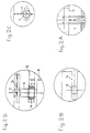
- Fig. 2 is a plan seen from above corresponding to FIG. 1.
- Figs. 2A to 2D are enlarged partial views of parts A, B, C and D surrounded in fig. 2.
- Fig. 3 is a plan seen from above similar to FIG. 2 and illustrating characteristic positions of groups printing.
- the tape leaves the dryer by wrapping around the cylinder 6 and leaves the group by cylinder 7. It enters the group following by cylinder 8 and in this group follows a identical route to that followed in the previous group.
- Fig. 2 is a top view showing the cylinders 7 and 8. These cylinders turn mad on their axes 9 and 10; they can be moved in a horizontal plane by rotating around the vertical pivot 11 (fig. 2C) and the vertical pivot sliding 12 (fig. 2D) and sliding in the guides or slides 13 and 14, which can be seen in fig. 1.
- Axes 9 and 10 are connected by connecting rods 15 and 16, the lengths are strictly identical. These connecting rods are linked to axes 9 and 10 by means of ball joints 17, 18, 19 and 20.
- the pivot 12 and the slide 14 are mounted on a support assembly 21 visible in FIG. 1 and who moves vertically relative to supports 22 and 23.
- the supports 22 and 23 carry the pivot 24 and the slide 25 of the cylinder 26, identical to cylinder 7 and by which the strip leaves the second group.
- the horizontal displacement of the cylinder 7 can be carried out by a flywheel or by a servomotor 27 (fig. 1).
- the vertical movement of the support assembly 21 can be carried out by a handwheel or by the servomotor 28 (fig. 1).
- the two servomotors 27 and 28 are shown on the front of the groups on the operator side but they can just as well be mounted on the opposite side, without it changing the description of operation. In this case, the figures would be symmetrical.
- the set of cylinders 7 and 8 and connecting rods 15 and 16 constitutes a deformable parallelogram.
- this parallelogram is a rectangle and the strip of material 29 which leaves the cylinder 7 along an axis perpendicular to it is brought to cylinder 8 too along the perpendicular axis of the latter.
- the path of the strip is will do without more constraint on it than if the two groups were perfectly aligned because the band 29 connects two cylinders 7 and 8 parallel, although they are not perfectly located in the same plane and part 30 of the strip connects two cylinders 8 and 31 of the second group which are parallel by construction.
- Aligning a machine can be done much more quickly and with much freer tolerances than those that are generally necessary.
- this alignment can be done without major concern for possible movements of groups in the future due to ground movements for example because, whatever happens, the strip path thanks to the guaranteed parallelism of the cylinders 7 and 8, on the one hand, and 8 and 31, on the other hand, will be always without constraint. You just have to move horizontally the cylinder 7 to bring the strip of material in the middle axis of the second group. Whereas in a conventional press, it would be necessary to carry out a new alignment.
- This same horizontol movement of cylinder 7 can be used to move the tape printed by the first group in the next group and therefore adjust the lateral marking colors without the need to move in the axially neither the engraved cylinder 32 nor the entire second printing group.
- the set of cylinders 7 and 8 and connecting rods 15 and 16 will be deformed into a parallelogram without the band 29 being constrained because the two cylinders 7 and 8 always remain parallel.
- the passage of the tape is as direct as in a group whose identification is adjusted by means of a differential and does not have the disadvantage of winding and the additional elongation that we encounter with a register integrated into the group.
- the invention is described in relation to a set of two groups printing according to the process rotogravure. It is obvious that this number is not limiting and that a greater number of printing groups can be aligned to form a press. Likewise, the following description is not limited to the process rotogravure. It can be applied to any other process using a similar strip passage and working by successive operations on the running of this strip.
Abstract
Description
Cette invention a pour but, tout en rendant très facile la mise en ligne d'une machine travaillant sur le défilement d'un matériau en bande, machine composée de plusieurs groupes de travail successifs, de simplifier sa construction et de grouper en un seul mécanisme trois fonctions habituellement séparées : alignement, repérage longitudinal et repérage latéral. Ces fonctions sont particulièrement importantes dans les machines d'impression, plus particulièrement les rotatives.This invention aims, while making it very easy to online setting of a scrolling machine of a strip material, machine composed of several groups successive work, to simplify its construction and usually group three functions into a single mechanism separate: alignment, longitudinal marking and marking lateral. These functions are particularly important in printing machines, especially rotary.
Dans une machine rotative, par exemple une rotative hélio, imprimant un matériau en bande, lorsque celle-ci va d'un cylindre à un autre et que ces deux cylindres ne sont pas parfaitement parallèles, les fibres extérieures de la bande ne sont pas tendues avec la même contrainte et de ce fait ne se trouvent pas en équilibre.In a rotary machine, for example a rotogravure press, printing a strip material, when this goes from one cylinder to another and that these two cylinders are not perfectly parallel, the outer fibers of the strip are not stretched with the same constraint and therefore do not are not in balance.
Il résulte de ce déséquilibre des mouvements latéraux du matériau et il devient alors impossible de maintenir la stabilité du repérage entre les couleurs successivement imprimées. Pour éviter ce déséquilibre, il est indispensable d'obtenir un alignement parfait des groupes imprimants, qui s'obtient après un travail minutieux de nivellement et de mise en parallèle.It results from this imbalance of the lateral movements of the material and then it becomes impossible to maintain the stable registration between colors successively printed. To avoid this imbalance, it is essential to obtain perfect alignment of the printing units, which is obtained after careful work of leveling and parallel.
Malheureusement, la réussite de ce travail n'est pas toujours vérifiée dans la pratique du fait :
- d'une part, des empilages et des tolérances des cotes dans la construction du groupe et de son séchage,
- d'autre part, de la mobilité de certains sols sur lesquels sont implantées les machines ce qui fait qu'une machine parfaitement alignée lors de son installation ne l'est plus après un certain temps.
- on the one hand, stacks and dimensional tolerances in the construction of the group and its drying,
- on the other hand, the mobility of certain floors on which the machines are installed, which means that a machine that is perfectly aligned during its installation is no longer so after a certain time.
Il faut donc assurer quoi qu'il arrive que le cylindre de sortie d'un groupe précédent soit parallèle au cylindre du groupe suivant. Ces deux cylindres ne doivent pas être nécessairement dans le même plan. En effet s'il existe entre leurs axes un petit angle dans une projection sur un plan parallèle aux deux cylindres, la bande de matériau trouvera facilement une position d'équilibre, de telle façon que les fibres extérieures soient tendues avec la même contrainte. Il est évident dans ce cas que les tensions des fibres extérieures seront plus fortes que la tension de la fibre médiane.So whatever happens, the cylinder of exit from a previous group be parallel to the cylinder of next group. These two cylinders should not be necessarily in the same plane. Indeed if there is between their axes a small angle in a projection on a plane parallel to the two cylinders, the strip of material will find easily an equilibrium position, so that the outer fibers are stretched with the same stress. he it is obvious in this case that the tensions of the fibers fibers will be stronger than the tension of the fiber median.
La différence de tension sera d'autant plus grande que l'angle projeté sur un plan parallèle aux deux cylindres sera grand.The difference in voltage will be all the greater as the angle projected on a plane parallel to the two cylinders will be tall.
Cependant, si l'angle projeté peut être considéré comme un infiniment petit du premier ordre, la différence entre les tensions extérieures et la tension médiane sera un infiniment petit du second ordre. Ceci revient à dire que, pour des petits angles d'écart, toujours dans l'hypothèse où les deux cylindres sont parallèles, la différence de tension entre les fibres extérieures et médianes est négligeable.However, if the projected angle can be considered as a infinitely small of the first order, the difference between external tensions and the median tension will be an infinitely small of the second order. This amounts to saying that, for small angles of deviation, always assuming that the two cylinders are parallel, the voltage difference between the outer and middle fibers is negligible.
Ce principe est bien connu des constructeurs de machines rotatives. Il est notamment utilisé avec succès dans les mécanismes de guidage de bande.This principle is well known to machine builders rotary. It is notably used with success in tape guiding mechanisms.
Dans une rotative hélio, la fonction de repérage latéral entre les couleurs est généralement obtenue par le déplacement axial des cylindres gravés. Ceci conduit à des mécanismes complexes, avec en plus l'inconvénient qu'un cylindre mobile dans le sens axial ne pourra pas être aussi rigide dans l'espace qu'un cylindre monté fixe par rapport au bâti.In a rotogravure press, the lateral tracking function between colors is usually obtained by the axial displacement of the engraved cylinders. This leads to complex mechanisms, with the additional disadvantage that cylinder movable in the axial direction cannot be as rigid in space that a mounted cylinder fixes relative to the built.
Pour pallier cet inconvénient, certains constructeurs ont choisi de déplacer latéralement le groupe entier sur son socle, à la manière d'une table de machine-outil. Il est évident, dans ce cas, bien que le cylindre gravé soit solidement lié au bâti, que tout le groupe est moins stable que s'il était rigidement fixé au sol.To overcome this drawback, some manufacturers have chose to move the whole group laterally on its base, like a machine tool table. It is obvious, in this case, although the engraved cylinder is solidly linked to the building, that the whole group is less stable only if it was rigidly fixed to the ground.
La fonction de repérage longitudinal est généralement obtenue au moyen d'un cylindre de renvoi mobile, appelé registre. Le mécanisme du registre est intégré au groupe et le mouvement du cylindre peut être manuel ou motorisé. Dans ce dernier cas, il est possible de rendre le repérage automatique au moyen d'un servomécanisme électronique.The longitudinal tracking function is generally obtained by means of a movable return cylinder, called a register. The register mechanism is integrated into the group and movement of the cylinder can be manual or motorized. In this last In this case, it is possible to make automatic tracking by means of an electronic servomechanism.
Ce système présente l'inconvénient, d'une part, d'allonger la bande entre deux groupes et par conséquent d'augmenter la constante de temps du système et, d'autre part, de faire varier la longueur de la bande dans la machine, à la suite des corrections, ce qui a pour conséquence de modifier inutilement le repérage des couleurs consécutives à celle qui vient d'être corrigée.This system has the drawback, on the one hand, of lengthening the band between two groups and therefore increase the system time constant and on the other hand to do vary the length of the tape in the machine, following corrections, which has the effect of modifying unnecessarily the identification of colors consecutive to that which has just been corrected.
Pour pallier ces inconvénients, certains constructeurs ont choisi d'effectuer le repérage longitudinal au moyen d'une transmission par différentiel de la commande au cylindre gravé. Ce mécanisme supprime totalement les deux inconvénients ci-dessus mais introduit dans les organes de transmission des jeux qui peuvent être nuisibles à la stabilité du repérage. To overcome these drawbacks, some manufacturers have chosen to perform longitudinal tracking using a differential transmission of the control to the cylinder serious. This mechanism completely removes both disadvantages above but introduced into the organs of transmission of games that may be harmful to the tracking stability.
Finalement et malgré ces inconvénients, le repérage par registre est très souvent préféré au repérage par différentiel.Finally and despite these drawbacks, the identification by register is very often preferred to identification by differential.
Dans le système, objet de cette invention, les trois fonctions, qui sont à la base de la stabilité et de la précision d'une rotative hélio, sont groupées dans un seul mécanisme très simple.In the system, object of this invention, the three functions, which are the basis of stability and precision of a rotogravure press, are grouped in one very simple mechanism.
Avec ce système, les groupes imprimants peuvent être solidement fixés au sol, les cylindres gravés peuvent être montés rigidement entre les bâtis de la machine, le jeu dans les transmissions peut être réduit au minimum et la longueur de la bande peut être aussi courte que dans une machine, dont le repérage est effectué au moyen d'un différentiel.With this system, the printing units can be securely fixed to the ground, the engraved cylinders can be rigidly mounted between the machine frames, the play in transmissions can be minimized and length tape can be as short as in a machine, which tracking is carried out by means of a differential.
Ceci conduit, par comparaison aux machines classiques, à une construction nettement plus économique plus robuste et un résultat final plus précis.This leads, compared to conventional machines, to a significantly more economical construction more robust and a more precise end result.
Conformément à l'invention, le dispositif de mise en ligne d'une bande utilisée dans une machine rotative d'impression comportant au moins deux groupes d'impression munis chacun d'un cylindre d'entrée et d'un cylindre de sortie pour la bande est caractérisé en ce que le cylindre de sortie d'un premier groupe est relié au cylindre d'entrée d'un second groupe pour constituer un parallélogramme déformable et en ce qu'au moins les cylindres de sortie et d'entrée de chaque groupe sont reliés respectivement à des mécanismes de déplacement.In accordance with the invention, the line-up device of a strip used in a rotary printing machine comprising at least two printing units each provided an inlet cylinder and an outlet cylinder for the strip is characterized in that the outlet cylinder of a first group is connected to the input cylinder of a second group to form a deformable parallelogram and in this that at least the output and input cylinders of each group are respectively linked to mechanisms of displacement.
Une forme de réalisation de l'objet de l'invention est représentée, à titre d'exemple non limitatif, aux dessins annexés. One embodiment of the subject of the invention is shown, by way of nonlimiting example, in the drawings attached.
Diverses autres caractéristiques de l'invention ressortent d'ailleurs de la description détaillée qui suit.Various other features of the invention emerge moreover from the detailed description which follows.
La fig. 1 est une élévation schématique du dispositif de l'invention mis en oeuvre dans un ensemble de deux groupes d'impression.Fig. 1 is a schematic elevation of the device the invention implemented in a set of two groups printing.
La fig. 2 est un plan vu de dessus correspondant à la fig. 1.Fig. 2 is a plan seen from above corresponding to FIG. 1.
Les fig. 2A à 2D sont des vues partielles agrandies des parties A, B, C et D entourées à la fig. 2.Figs. 2A to 2D are enlarged partial views of parts A, B, C and D surrounded in fig. 2.
La fig. 3 est un plan vu de dessus analogue à la fig. 2 et illustrant des positions caractéristiques des groupes d'impression.Fig. 3 is a plan seen from above similar to FIG. 2 and illustrating characteristic positions of groups printing.
La bande qui quitte le cylindre gravé 1, après avoir été
imprimée par la pression du cylindre 2, passe dans un sécheur
3 où elle s'enroule autour des cylindres de renvoi 4 et 5,
qui la supportent sur la face non imprimée, pendant que de
l'air chaud est soufflé sur la face qui vient d'être imprimée.The strip which leaves the engraved cylinder 1, after having been
printed by the pressure of cylinder 2, passes through a
La bande sort du sécheur en s'enroulant autour du cylindre 6
et quitte le groupe par le cylindre 7. Elle entre dans le
groupe suivant par le cylindre 8 et suit dans ce groupe un
trajet identique à celui suivi dans le groupe précédent.The tape leaves the dryer by wrapping around the cylinder 6
and leaves the group by
La fig. 2 est une vue de dessus, qui montre les cylindres 7
et 8. Ces cylindres tournent fous sur leurs axes 9 et 10 ;
ils peuvent être déplacés dans un plan horizontal en pivotant
autour du pivot vertical 11 (fig. 2C) et du pivot vertical
coulissant 12 (fig. 2D) et en coulissant dans les guides ou
coulisses 13 et 14, qu'on peut voir à la fig. 1. Les axes 9
et 10 sont reliés par des bielles 15 et 16, dont les
longueurs sont rigoureusement identiques. Ces bielles sont
liées aux axes 9 et 10 au moyen des rotules 17, 18, 19 et 20.Fig. 2 is a top view showing the
Aux fig. 2 et 2D, le pivot 12 et la coulisse 14 sont montés
sur un ensemble support 21 visible à la fig. 1 et qui se
déplace verticalement par rapport aux supports 22 et 23. Les
supports 22 et 23 portent le pivot 24 et la coulisse 25 du
cylindre 26, identiuque au cylindre 7 et par lequel la bande
quitte le deuxième groupe.In fig. 2 and 2D, the
Le déplacement horizontal du cylindre 7 peut être effectué
par un volant ou par un servomoteur 27 (fig. 1). Le
déplacement vertical de l'ensemble support 21 peut être
effectué par un volant ou par le servomoteur 28 (fig. 1).The horizontal displacement of the
Les deux servomoteurs 27 et 28 sont figurés sur l'avant des
groupes, du côté de l'opérateur mais ils peuvent tout aussi
bien être montés sur le côté opposé, sans que cela change la
description du fonctionnement. Dans ce cas, les figures
seraient symétriques.The two
A la fig. 2, l'ensemble des cylindres 7 et 8 et des bielles
15 et 16 constitue un parallélogramme déformable. Dans le cas
de la figure, ce parallélogramme est un rectangle et la bande
de matériau 29 qui quitte le cylindre 7 suivant un axe
perpendiculaire à celui-ci est amenée au cylindre 8 aussi
suivant l'axe perpendiculaire de ce dernier.In fig. 2, the set of
En supposant les deux groupes parfaitement horizontaux de niveau et parallèles entre eux, la bande suivra dans le cas de la figure un trajet sans contrainte et parfaitement centré par rapport aux deux groupes.Assuming the two perfectly horizontal groups of level and parallel to each other, the strip will follow in the case from the figure a perfectly centered and unconstrained path compared to the two groups.
En supposant maintenant que les deux groupes ne soient pas
parfaitement horizontaux ni parfaitement de niveau, ni
parfaitement parallèles, comme c'est souvent le cas en
pratique et comme cela est représenté sur la fig. 3 en vue de
dessus, il est toujours possible, en déplaçant
horizontalement le cylindre 7 de trouver un angle tel que la
bande 29 quittant le premier groupe dans l'axe médian du
cylindre 7 soit amenée au cylindre 8 aussi selon son axe
médian. Il est à remarquer dans ce cas, que la distance entre
les deux groupes peut être différente de celle du cas de la
fig. 1 sans que cela entraíne une contrainte sur la bielle 16
grâce au coulissement du pivot 12. Le trajet de la bande se
fera sans plus de contrainte sur celle-ci que si les deux
groupes étaient parfaitement alignés car la bande 29 relie
deux cylindres 7 et 8 parallèles, bien qu'ils ne soient pas
parfaitement situés dans le même plan et la partie 30 de la
bande relie deux cylindres 8 et 31 du deuxième groupe qui
sont parallèles par construction.Now assuming that the two groups are not
perfectly horizontal neither perfectly level nor
perfectly parallel, as is often the case in
practical and as shown in fig. 3 with a view to
above it is always possible, by moving
horizontally the
L'alignement d'une machine peut se faire ainsi beaucoup plus
rapidement et avec des tolérances beaucoup plus libres que
celles qui sont généralement nécessaires. De plus, cet
alignement pourra se faire sans souci majeur pour des
déplacements éventuels des groupes dans l'avenir dus à des
mouvements du sol par exemple car, quoi qu'il arrive, le
trajet de la bande grâce au parallélisme assuré des cylindres
7 et 8, d'une part, et 8 et 31, d'autre part, se fera
toujours sans contrainte. Il suffira simplement de déplacer
horizontalement le cylindre 7 pour ramener la bande de
matériau dans l'axe médian du deuxième groupe. Alors que dans
une rotative classique, il serait nécessaire de procéder à un
nouvel alignement.Aligning a machine can be done much more
quickly and with much freer tolerances than
those that are generally necessary. In addition, this
alignment can be done without major concern for
possible movements of groups in the future due to
ground movements for example because, whatever happens, the
strip path thanks to the guaranteed parallelism of the
Ce même mouvement horizontol du cylindre 7 peut être utilisé
pour déplacer la bande imprimée par le premier groupe dans le
groupe suivant et par conséquent ajuster le repérage latéral
des couleurs sans qu'il soit nécessaire de déplacer dans le
sens axial ni le cylindre gravé 32 ni l'ensemble du deuxième
groupe imprimant. Dans ce cas, l'ensemble des cylindres 7 et
8 et des bielles 15 et 16 sera déformé en parallélogramme
sans que la bande 29 soit contrainte pour autant car les deux
cylindres 7 et 8 restent toujours parallèles.This same horizontol movement of
De même, un déplacement angulaire faible vers le haut ou vers
le bas des bielles 15 et 16 au moyen du servomoteur 28
allongera ou raccourcira la bande entre les cylindres gravés
1 et 32 et, par conséquent, permettra d'ajuster le repérage
longitudinal entre les couleurs imprimées.Likewise, a slight angular displacement upwards or towards
the bottom of the connecting
Dans ce cas, le passage de la bande est aussi direct que dans un groupe dont le repérage est réglé au moyen d'un différentiel et n'a pas l'inconvénient de l'enroulement et de l'allongement supplémentaires que l'on rencontre avec un registre intégré au groupe.In this case, the passage of the tape is as direct as in a group whose identification is adjusted by means of a differential and does not have the disadvantage of winding and the additional elongation that we encounter with a register integrated into the group.
Dans ce qui précède, l'invention est décrite en relation avec un ensemble de deux groupes imprimant selon le procédé d'héliogravure. Il est évident que ce nombre n'est pas limitatif et qu'un plus grand nombre de groupes imprimants peuvent être alignés pour constituer une rotative. De même, la description qui suit n'est pas limitée au procédé d'héliogravure. Elle peut s'appliquer à toute autre procédé utilisant un passage de bande similaire et travaillant par des opérations successives sur le défilement de cette bande.In the foregoing, the invention is described in relation to a set of two groups printing according to the process rotogravure. It is obvious that this number is not limiting and that a greater number of printing groups can be aligned to form a press. Likewise, the following description is not limited to the process rotogravure. It can be applied to any other process using a similar strip passage and working by successive operations on the running of this strip.
L'invention n'est pas limitée aux exemples de réalisation représentés et décrits en détail car diverses modifications peuvent y être apportées sans sortir de son cadre.The invention is not limited to the exemplary embodiments shown and described in detail because various modifications can be made without departing from its scope.
Claims (8)
Priority Applications (2)
| Application Number | Priority Date | Filing Date | Title |
|---|---|---|---|
| DE1996603202 DE69603202T2 (en) | 1996-11-27 | 1996-11-27 | Web alignment device for use in a rotary printing press |
| EP19960402560 EP0860274B1 (en) | 1996-11-27 | 1996-11-27 | Web aligning device used in a rotary printing machine |
Applications Claiming Priority (1)
| Application Number | Priority Date | Filing Date | Title |
|---|---|---|---|
| EP19960402560 EP0860274B1 (en) | 1996-11-27 | 1996-11-27 | Web aligning device used in a rotary printing machine |
Publications (2)
| Publication Number | Publication Date |
|---|---|
| EP0860274A1 true EP0860274A1 (en) | 1998-08-26 |
| EP0860274B1 EP0860274B1 (en) | 1999-07-07 |
Family
ID=8225323
Family Applications (1)
| Application Number | Title | Priority Date | Filing Date |
|---|---|---|---|
| EP19960402560 Expired - Lifetime EP0860274B1 (en) | 1996-11-27 | 1996-11-27 | Web aligning device used in a rotary printing machine |
Country Status (2)
| Country | Link |
|---|---|
| EP (1) | EP0860274B1 (en) |
| DE (1) | DE69603202T2 (en) |
Cited By (2)
| Publication number | Priority date | Publication date | Assignee | Title |
|---|---|---|---|---|
| GB2340232A (en) * | 1998-07-31 | 2000-02-16 | Hewlett Packard Co | Detecting fluid levels in a container |
| EP1213142A2 (en) * | 2000-12-07 | 2002-06-12 | Heidelberger Druckmaschinen Aktiengesellschaft | Roll pair arrangement |
Families Citing this family (1)
| Publication number | Priority date | Publication date | Assignee | Title |
|---|---|---|---|---|
| JP4982313B2 (en) | 2007-09-20 | 2012-07-25 | リョービ株式会社 | Transfer film winding method and printing paper transfer device |
Citations (6)
| Publication number | Priority date | Publication date | Assignee | Title |
|---|---|---|---|---|
| DE744927C (en) * | 1939-12-12 | 1944-02-22 | Vomag Vogtlaendische Maschinen | Register setting device for rotary printing machines, in particular rotogravure printing machines |
| US3373288A (en) * | 1965-08-26 | 1968-03-12 | Web Press Eng Inc | Photosensitive web shifting apparatus |
| US4069959A (en) * | 1976-10-27 | 1978-01-24 | Butler Automatic, Inc. | Web guide apparatus |
| GB2190042A (en) * | 1986-05-01 | 1987-11-11 | Rofrep Ltd | Multicolour printing of successive images on elongate web |
| WO1994020299A1 (en) * | 1993-03-09 | 1994-09-15 | Seroma | Device for the adjustment of a flexographic printing machine unit |
| EP0683123A1 (en) * | 1994-05-20 | 1995-11-22 | De La Rue Giori S.A. | Rotary printing machine provided with a register device for aligning the paper web |
-
1996
- 1996-11-27 DE DE1996603202 patent/DE69603202T2/en not_active Expired - Fee Related
- 1996-11-27 EP EP19960402560 patent/EP0860274B1/en not_active Expired - Lifetime
Patent Citations (6)
| Publication number | Priority date | Publication date | Assignee | Title |
|---|---|---|---|---|
| DE744927C (en) * | 1939-12-12 | 1944-02-22 | Vomag Vogtlaendische Maschinen | Register setting device for rotary printing machines, in particular rotogravure printing machines |
| US3373288A (en) * | 1965-08-26 | 1968-03-12 | Web Press Eng Inc | Photosensitive web shifting apparatus |
| US4069959A (en) * | 1976-10-27 | 1978-01-24 | Butler Automatic, Inc. | Web guide apparatus |
| GB2190042A (en) * | 1986-05-01 | 1987-11-11 | Rofrep Ltd | Multicolour printing of successive images on elongate web |
| WO1994020299A1 (en) * | 1993-03-09 | 1994-09-15 | Seroma | Device for the adjustment of a flexographic printing machine unit |
| EP0683123A1 (en) * | 1994-05-20 | 1995-11-22 | De La Rue Giori S.A. | Rotary printing machine provided with a register device for aligning the paper web |
Cited By (5)
| Publication number | Priority date | Publication date | Assignee | Title |
|---|---|---|---|---|
| GB2340232A (en) * | 1998-07-31 | 2000-02-16 | Hewlett Packard Co | Detecting fluid levels in a container |
| US6274880B1 (en) | 1998-07-31 | 2001-08-14 | Hewlett-Packard Company | Fluid level sensing system and method having controlled surface pairs |
| GB2340232B (en) * | 1998-07-31 | 2003-09-03 | Hewlett Packard Co | Method and apparatus for detecting fluid level in a fluid container |
| EP1213142A2 (en) * | 2000-12-07 | 2002-06-12 | Heidelberger Druckmaschinen Aktiengesellschaft | Roll pair arrangement |
| EP1213142A3 (en) * | 2000-12-07 | 2003-03-19 | Heidelberger Druckmaschinen Aktiengesellschaft | Roll pair arrangement |
Also Published As
| Publication number | Publication date |
|---|---|
| DE69603202D1 (en) | 1999-08-12 |
| EP0860274B1 (en) | 1999-07-07 |
| DE69603202T2 (en) | 2000-05-18 |
Similar Documents
| Publication | Publication Date | Title |
|---|---|---|
| EP0860274B1 (en) | Web aligning device used in a rotary printing machine | |
| FR2646633A1 (en) | FOLDING DEVICE IN A CORRUGATED BOX MANUFACTURING MACHINE | |
| EP0983951B1 (en) | Correcting device with rollers or belts for lateral aligning, during the processing, of articles such as sheets or blanks, partially folded in a folding-gluing machine | |
| FR2505734A1 (en) | ROTARY PRESS WITH COILS | |
| FR2689490A1 (en) | Device for adjusting the lateral position of a continuous sheet | |
| FR2740725A1 (en) | Alignment feed for rotary printer feed belt | |
| BE1010857A3 (en) | Device for aligning a strip used in a rotary press | |
| US5890672A (en) | Surface winder apparatus and method | |
| EP0381845B1 (en) | Device for aligning box blanks in a machine for treating them | |
| EP0610791B1 (en) | Device for aligning box blanks in a machine for treating them | |
| FR2802192A1 (en) | DEVICE FOR GUIDING STRIPS OF MATERIAL IN ROTARY PRINTING PRESSES | |
| FR2577539A1 (en) | DEVICE FOR ADJUSTING THE POSITION OF A CONTINUOUSLY MOVED BAND, FOR EXAMPLE OF A PAPER BAND ON ROTARY PRINTING MACHINES | |
| FR2535298A1 (en) | DEVICE FOR CONNECTING EACH OTHER TWO COILS OF BAND MATERIAL | |
| FR2726502A1 (en) | DEVICE FOR FEEDING A STRIP OF PAPER TO A FOLDER OF A ROLLING PRINTING ROTARY | |
| CH365259A (en) | Mechanism causing a section of tape to be transported step by step over a determined sector, independently of the movements made by the rest of the tape | |
| FR2690643A1 (en) | Device for adjusting a cutting blade for cutting continuous strips of material | |
| BE1003884A5 (en) | Tufting PROCESS AND DEVICE FOR IMPLEMENTING THE METHOD. | |
| FR2535299A1 (en) | Printed sheet folding machine | |
| FR2549108A1 (en) | DEVICE FOR TREATING TUBULAR TEXTILE MATERIAL EQUIPPED WITH AT LEAST ONE CYLINDRICAL EXCHANGER | |
| FR2581664A1 (en) | STRETCHING APPARATUS | |
| FR2601935A1 (en) | CORRECTIVE CYLINDERS, ESPECIALLY FOR A ROTARY FOLDING APPARATUS, IN PARTICULAR IN THE MANUFACTURE OF PRINTING PRODUCTS | |
| BE1005324A3 (en) | Power delivery sheet roll of a plot and method for setting the route route leaf roll. | |
| NL1005022C2 (en) | Alignment feed for rotary printer feed belt - has outlet cylinder of group connected to input cylinder of second group to form deformable parallelogram | |
| FR2797800A1 (en) | SUPPORT AND ROTARY MOUNTING UNIT FOR TAPE ROLLERS, ESPECIALLY PRINTED TAPES, AND FOLDER USING SUCH A UNIT | |
| JPH0372973B2 (en) |
Legal Events
| Date | Code | Title | Description |
|---|---|---|---|
| GRAG | Despatch of communication of intention to grant |
Free format text: ORIGINAL CODE: EPIDOS AGRA |
|
| PUAI | Public reference made under article 153(3) epc to a published international application that has entered the european phase |
Free format text: ORIGINAL CODE: 0009012 |
|
| 17P | Request for examination filed |
Effective date: 19961202 |
|
| AK | Designated contracting states |
Kind code of ref document: A1 Designated state(s): CH DE GB IT LI |
|
| GRAG | Despatch of communication of intention to grant |
Free format text: ORIGINAL CODE: EPIDOS AGRA |
|
| GRAH | Despatch of communication of intention to grant a patent |
Free format text: ORIGINAL CODE: EPIDOS IGRA |
|
| GRAH | Despatch of communication of intention to grant a patent |
Free format text: ORIGINAL CODE: EPIDOS IGRA |
|
| AKX | Designation fees paid |
Free format text: CH DE GB IT LI |
|
| RBV | Designated contracting states (corrected) |
Designated state(s): CH DE GB IT LI |
|
| GRAA | (expected) grant |
Free format text: ORIGINAL CODE: 0009210 |
|
| AK | Designated contracting states |
Kind code of ref document: B1 Designated state(s): CH DE GB IT LI |
|
| REG | Reference to a national code |
Ref country code: CH Ref legal event code: EP |
|
| REF | Corresponds to: |
Ref document number: 69603202 Country of ref document: DE Date of ref document: 19990812 |
|
| ITF | It: translation for a ep patent filed |
Owner name: STUDIO ING. ALFREDO RAIMONDI |
|
| RAP2 | Party data changed (patent owner data changed or rights of a patent transferred) |
Owner name: ATN |
|
| PLBE | No opposition filed within time limit |
Free format text: ORIGINAL CODE: 0009261 |
|
| STAA | Information on the status of an ep patent application or granted ep patent |
Free format text: STATUS: NO OPPOSITION FILED WITHIN TIME LIMIT |
|
| PGFP | Annual fee paid to national office [announced via postgrant information from national office to epo] |
Ref country code: DE Payment date: 20000531 Year of fee payment: 4 |
|
| 26N | No opposition filed | ||
| PG25 | Lapsed in a contracting state [announced via postgrant information from national office to epo] |
Ref country code: GB Free format text: LAPSE BECAUSE OF NON-PAYMENT OF DUE FEES Effective date: 20001127 |
|
| PG25 | Lapsed in a contracting state [announced via postgrant information from national office to epo] |
Ref country code: LI Free format text: LAPSE BECAUSE OF NON-PAYMENT OF DUE FEES Effective date: 20001130 Ref country code: CH Free format text: LAPSE BECAUSE OF NON-PAYMENT OF DUE FEES Effective date: 20001130 |
|
| REG | Reference to a national code |
Ref country code: CH Ref legal event code: PL |
|
| GBPC | Gb: european patent ceased through non-payment of renewal fee |
Effective date: 20001127 |
|
| PG25 | Lapsed in a contracting state [announced via postgrant information from national office to epo] |
Ref country code: DE Free format text: LAPSE BECAUSE OF NON-PAYMENT OF DUE FEES Effective date: 20010801 |
|
| PG25 | Lapsed in a contracting state [announced via postgrant information from national office to epo] |
Ref country code: IT Free format text: LAPSE BECAUSE OF NON-PAYMENT OF DUE FEES;WARNING: LAPSES OF ITALIAN PATENTS WITH EFFECTIVE DATE BEFORE 2007 MAY HAVE OCCURRED AT ANY TIME BEFORE 2007. THE CORRECT EFFECTIVE DATE MAY BE DIFFERENT FROM THE ONE RECORDED. Effective date: 20051127 |