EP0859969B1 - Method and device for manufacturing a broadband cholesteric polarizer - Google Patents
Method and device for manufacturing a broadband cholesteric polarizer Download PDFInfo
- Publication number
- EP0859969B1 EP0859969B1 EP97925235A EP97925235A EP0859969B1 EP 0859969 B1 EP0859969 B1 EP 0859969B1 EP 97925235 A EP97925235 A EP 97925235A EP 97925235 A EP97925235 A EP 97925235A EP 0859969 B1 EP0859969 B1 EP 0859969B1
- Authority
- EP
- European Patent Office
- Prior art keywords
- edge position
- radiation
- band
- desired edge
- intensity
- Prior art date
- Legal status (The legal status is an assumption and is not a legal conclusion. Google has not performed a legal analysis and makes no representation as to the accuracy of the status listed.)
- Expired - Lifetime
Links
- 230000003098 cholesteric effect Effects 0.000 title claims abstract description 34
- 238000000034 method Methods 0.000 title claims abstract description 29
- 238000004519 manufacturing process Methods 0.000 title claims abstract description 15
- 230000005855 radiation Effects 0.000 claims abstract description 47
- 239000000178 monomer Substances 0.000 claims abstract description 21
- 230000009257 reactivity Effects 0.000 claims abstract description 7
- 206010073306 Exposure to radiation Diseases 0.000 claims abstract description 3
- 239000000758 substrate Substances 0.000 claims description 27
- 230000005540 biological transmission Effects 0.000 claims description 11
- 238000005286 illumination Methods 0.000 claims description 5
- 230000003287 optical effect Effects 0.000 claims description 5
- 238000005259 measurement Methods 0.000 claims description 3
- 239000007788 liquid Substances 0.000 claims description 2
- 230000001747 exhibiting effect Effects 0.000 claims 2
- 238000006116 polymerization reaction Methods 0.000 description 11
- 239000000203 mixture Substances 0.000 description 10
- 239000000463 material Substances 0.000 description 9
- 150000001875 compounds Chemical class 0.000 description 3
- 238000010924 continuous production Methods 0.000 description 3
- 239000002178 crystalline material Substances 0.000 description 3
- 239000011888 foil Substances 0.000 description 3
- 239000004642 Polyimide Substances 0.000 description 2
- 238000010923 batch production Methods 0.000 description 2
- 238000009792 diffusion process Methods 0.000 description 2
- 230000007935 neutral effect Effects 0.000 description 2
- 230000010287 polarization Effects 0.000 description 2
- 229920001721 polyimide Polymers 0.000 description 2
- KWVGIHKZDCUPEU-UHFFFAOYSA-N 2,2-dimethoxy-2-phenylacetophenone Chemical compound C=1C=CC=CC=1C(OC)(OC)C(=O)C1=CC=CC=C1 KWVGIHKZDCUPEU-UHFFFAOYSA-N 0.000 description 1
- OXBLVCZKDOZZOJ-UHFFFAOYSA-N 2,3-Dihydrothiophene Chemical compound C1CC=CS1 OXBLVCZKDOZZOJ-UHFFFAOYSA-N 0.000 description 1
- 239000004593 Epoxy Chemical class 0.000 description 1
- OWYWGLHRNBIFJP-UHFFFAOYSA-N Ipazine Chemical compound CCN(CC)C1=NC(Cl)=NC(NC(C)C)=N1 OWYWGLHRNBIFJP-UHFFFAOYSA-N 0.000 description 1
- VYPSYNLAJGMNEJ-UHFFFAOYSA-N Silicium dioxide Chemical compound O=[Si]=O VYPSYNLAJGMNEJ-UHFFFAOYSA-N 0.000 description 1
- QYKIQEUNHZKYBP-UHFFFAOYSA-N Vinyl ether Chemical class C=COC=C QYKIQEUNHZKYBP-UHFFFAOYSA-N 0.000 description 1
- 238000010521 absorption reaction Methods 0.000 description 1
- NIXOWILDQLNWCW-UHFFFAOYSA-M acrylate group Chemical group C(C=C)(=O)[O-] NIXOWILDQLNWCW-UHFFFAOYSA-M 0.000 description 1
- 150000001252 acrylic acid derivatives Chemical class 0.000 description 1
- 230000008033 biological extinction Effects 0.000 description 1
- 230000007423 decrease Effects 0.000 description 1
- 230000002349 favourable effect Effects 0.000 description 1
- 239000011521 glass Substances 0.000 description 1
- 230000001678 irradiating effect Effects 0.000 description 1
- NWVVVBRKAWDGAB-UHFFFAOYSA-N p-methoxyphenol Chemical compound COC1=CC=C(O)C=C1 NWVVVBRKAWDGAB-UHFFFAOYSA-N 0.000 description 1
- 229910052814 silicon oxide Inorganic materials 0.000 description 1
- 125000006850 spacer group Chemical group 0.000 description 1
- 230000002269 spontaneous effect Effects 0.000 description 1
- 239000003381 stabilizer Substances 0.000 description 1
- 239000000126 substance Substances 0.000 description 1
Images

Classifications
-
- G—PHYSICS
- G02—OPTICS
- G02B—OPTICAL ELEMENTS, SYSTEMS OR APPARATUS
- G02B5/00—Optical elements other than lenses
- G02B5/30—Polarising elements
- G02B5/3016—Polarising elements involving passive liquid crystal elements
Definitions
- the invention relates to a method of manufacturing a broadband cholesteric polarizer, in which a liquid-crystalline, cholesterically ordered layer comprising reactive chiral monomers and reactive nematogenic monomers of different reactivity is polymerized by exposure to radiation.
- the invention also relates to devices for carrying out the method in accordance with the invention.
- cholesteric polarizers and methods of manufacturing same are known per se, for example, from Patent Publications EP-A 404.939, EP-A 404.940 and WO 96/02016, which are all in the name of the current Applicant.
- Polarizers of this type comprise a thin layer of a cholesterically (i.e. chirally nematically) ordered material. This material contains chiral, liquid-crystalline molecules having such a structure that they order themselves more or less spontaneously into a spiral-shaped or helical structure.
- the pitch of this helix can be increased by adding a quantity of a non-chiral, liquid-crystalline (i.e. nematogenic) material to the chiral, liquid-crystalline material.
- the exact pitch is governed by the ratio between the quantities of chiral and non-chiral liquid-crystalline molecules as well as by their chemical structure.
- this material is provided in the form of a thin layer on a substrate or between two substrates, said helical structure assumes such an orientation that the axis of the helix extends transversely to the layer.
- a layer is capable of reflecting a narrow band of light whose wavelength corresponds to the product of the pitch and the refractive index of the material and whose direction of polarization corresponds to the handedness of the helical structure.
- a cholesteric layer can very suitably be used in an optical polarizer.
- the refractive index of a material is to be understood to mean in this context the geometric mean (n e +n o )/2 of the ordinary refractive index n o and the extraordinary refractive index n e of this material.
- Broadband cholesteric polarizers are distinguished from the customary cholesteric polarizers by the presence of a relatively broad reflection band.
- the bandwidth of the customary cholesteric polarizers is only approximately 40-50 nm. In the case of broadband polarizers, bandwidths of 100 nm, 150 nm, 200 nm and even more than 400 nm have been achieved.
- the band position of a cholesteric filter is defined as the center of the wavelength range in which the reflection takes place.
- a width of a band is defined as the difference in wavelength between the long-wave and the short-wave edge positions of the band.
- the wavelength of an edge position is defined as the wavelength at which the intensity amounts to 50% of the maximum intensity.
- EP 404.940 describes an elegant method of manufacturing a broadband cholesteric polarizer.
- use is made of a mixture comprising reactive chiral monomers and reactive nematogenic monomers, which exhibit a different reactivity.
- reactive monomers use can be made of compounds containing a reactive group on the basis of acrylates, epoxy compounds, vinylethers and thiolene systems, as described, inter alia, in US 5,188,760.
- Monomers containing different reactive groups generally exhibit a different reactivity. A difference in reactivity also occurs if one type of monomers contains one reactive group and the other type of monomers contains two (identical) reactive groups.
- a layer of this mixture is polymerized by means of (actinic) radiation, in particular UV radiation.
- actinic radiation in particular UV radiation.
- the conditions are selected in such a manner that during the polymerization operation a radiation profile of varied intensity is formed in the layer.
- diffusion processes take place in the cholesteric layer during polymerization.
- this cholesteric polarizer exhibits a relatively broad reflection band.
- the invention more particularly aims at providing a method of manufacturing broadband cholesteric polarizers of which the position of one of the two edges of the reflection band can be adjusted in a very reproducible manner.
- the method in accordance with the invention should enable these polarizers to be mass-produced.
- the invention is based on the experimentally gained insight that the intensity of the radiation used during polymerization plays an important part in the manufacture of broadband polarizers. It has been demonstrated that the eventually achieved bandwidth is governed to a substantial degree by the radiation intensity used. If use is made of a relatively high UV intensity (typically 0.5 mW/cm 2 or higher), the eventually achieved bandwidth is found to be relatively small, and it differs hardly from that of the unpolymerized mixture. If a relatively low radiation intensity (typically 0.05 mW/cm 2 or lower) is used, a much broader reflection band is obtained. See also Table I in US-A- 5,506,704.
- a colored, narrow reflection band is formed, which subsequently broadens into an uncolored, broadband reflection band.
- a substantial increase of the intensity causes the bandwidth obtained at that instant to be frozen, as it were. It has been demonstrated that the increase in intensity should preferably be a factor of 10 or more to bring about said frozen state. Preferably, this factor is 20 or more. Under these conditions, the cholesterically ordered layer becomes momentary polymerized.
- a preferred embodiment of the method in accordance with the invention is characterized in that the attainment of the desired edge position of the band is determined by means of a monochromatic photosensor, the wavelength used by said sensor corresponding to the wavelength of the desired edge position of the band.
- a photosensor comprises a photodetector as well as a monochromatic light source.
- a laser can very advantageously be used as the monochromatic light source in the sensor.
- the sensor can be used in reflection.
- Said sensor is constructed in such a manner that the monochromatic light, which emanates from the light source and which is used in the measuring operation, is directed to the layer to be polymerized.
- the monochromatic light which emanates from the light source and which is used in the measuring operation, is directed to the layer to be polymerized.
- this light will pass through the layer to be polymerized (transmission).
- reflection of the monochromatic light occurs.
- a proper positioning of the layer, the light source and the detector causes this light to be reflected at the detector. At this moment, the intensity of the polymerization radiation should be increased.
- a second polymerization lamp having a higher radiation intensity is activated or, preferably, a filter situated in front of the polymerization lamp is removed.
- a filter situated in front of the polymerization lamp is removed.
- use can also advantageously be made of a filter whose transmission is adjustable.
- the desired edge position of the band is determined by means of a transmission measurement.
- the sensor is constructed so that the light source and the detector are situated on either side of the layer to be polymerized. In this case, the sensor is activated as soon as the detector detects a substantial reduction in intensity of the light emanating from the light source.
- Such an arrangement has the advantage that the exact alignment of the layer to be polymerized does not affect the measuring results of the sensor.
- Another suitable embodiment of the method in accordance with the invention is characterized in that the liquid crystalline, cholesterically ordered layer is passed through an illumination tunnel which is provided with a number of compartments which comprise a radiation source as well as a light sensor by means of which the intensity of the radiation incident on the layer can be changed.
- This embodiment of the method in accordance with the invention enables broadband, cholesteric polarizers to be manufactured in a continuous process. This has a favorable effect on the cost price per unit area.
- the invention also relates to a device for manufacturing a broadband cholesteric polarizer, which is characterized by a radiation compartment comprising
- This device in accordance with the invention enables broadband polarizers to be manufactured in batch processes.
- the photodetector and the monochromatic light source are positioned in the radiation compartment in such a manner that the sensor measures in the transmission.
- the polarizer to be manufactured is situated between the detector and the light source during operation of the device.
- Another device in accordance with the invention which is used to manufacture a broadband cholesteric polarizer, is characterized in that the device comprises a number of radiation compartments, which are provided with
- This device in accordance with the invention enables broadband polarizers to be manufactured in a continuous process.
- the photodetector and the monochromatic light source are positioned in the radiation compartments in such a manner that the sensors measure in transmission.
- the - preferably elongated - substrate to be passed through the radiation compartments is situated between the detector and the light source during operation of the device.
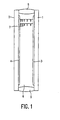
- Fig. 1 shows an embodiment of a broadband cholesteric polarizer which is manufactured by means of the method according to the invention.
- Said polarizer comprises two flat, transparent substrates 1 and 2, which are made, for example, of glass and which are positioned substantially parallel to each other and at some distance from each other.
- the facing surfaces of the substrates are provided with an orientation layer 3 and 4, for example, of rubbed polyimide or sputtered SiO x .
- a spacer 5 is provided at the edges of the substrates.
- a layer 6 of a cholesterically ordered polymeric material is situated between said two substrates.
- the axis of the molecular helix of the cholesterically ordered material extends transversely to the layer.
- the molecular helix has a variable pitch which increases continuously from one surface of layer 6 to the other surface. This is schematically shown by means of two spiral-shaped structures 7.
- the thickness of layer 6 typically ranges from 3 to 40 micrometers, preferably from 5 to 25 micrometers.
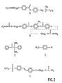
- the above-described embodiment of the cholesteric polarizer in accordance with the invention was manufactured as follows. First, a mixture containing reactive monomers was prepared. This mixture contained 35 wt. % of the chiral monomer A and 65 wt. % of the nematogenic monomer B. Monomer A contains one reactive group per molecule and monomer B contains two reactive groups per molecule. In this case, acrylate groups were used. The exact structural formulas of the monomers A and B are shown in Fig. 2. The difference in reactivity between both monomers can be attributed to the different number of reactive groups per molecule. Subsequently, 2 wt.
- the mixture thus prepared was subsequently provided between two transparent substrates. These substrates were provided with a layer of a rubbed polyimide. These layers serve to improve the alignment of the molecular helix, which develops spontaneously in the cholesteric mixture. It is noted that, in said method according to the invention, it is not absolutely necessary to use substrates which are provided with orientation layers. In the manufacture of (very) thin optically active layers, generally spontaneous orientation of the chiral and nematogrenic groups takes place. However, the presence of orientation layers during polymerization does lead to an improved orientation of the optically active layer, so that the optical properties of the polarizers are improved substantially.
- This device comprises a radiation compartment 11. This is provided with means for positioning the broadband cholesteric polarizer to be manufactured. In the device shown, these means are constructed as support bodies 12.
- the polarizer comprises two substrates 13 and a cholesterically ordered layer 14 situated between said substrates. It is noted that the method and device in accordance with the invention can also be used to manufacture polarizers in which only one substrate is used.
- Compartment 11 further comprises a radiation source in the form of an UV lamp.
- the power of the lamp and the distance between the lamp and the polarizer to be irradiated are selected in such a manner that the average illumination intensity to which the cholesteric layer is exposed during operation of the device is approximately 0.9 mW/cm 2 .
- a neutral-density filter 16 whose position or transmission is adjustable is arranged between the UV lamp and the polarizer. When the filter operates at maximum capacity, the radiation originating from the UV lamp is filtered in such a manner that the average illumination intensity on the polarizer is only approximately 0.03 mW/cm 2 .
- Compartment 11 also comprises a photosensor which consists of a monochromatic light source 17 in the form of a laser and of a photodetector 18.
- the wavelength of the laser is selected to be such that it is equal to the edge position of the broadband polarizer to be manufactured.
- the sensor measures in transmission, so that the detector and the light source are situated on opposite sides of the polarizer which is the subject of measurements.
- the sensor is coupled to the filter 16.
- the filter 16 As soon as the transmission of the polarizer decreases substantially (50% or more) during illumination, the sensor supplies a signal which causes the neutral density filter 16 to be activated. Depending on the type of filter, this is either removed from its position between the radiation source 15 and the polarizer or the transmission of the filter is maximized.
- the radiation intensity on the polarizer increases by a factor of 30, which results in the instantaneous, complete polymerization of the cholesteric layer.
- the bandwidth as well as the exact position of one of the band edges is defined.
- Fig. 4 is a schematic, sectional view of a device in accordance with the invention for mass-producing broadband cholesteric polarizers.
- This device comprises a temperature-controlled radiation tunnel 21 which accommodates a number of radiation compartments 22.
- Said radiation tunnel is provided with means 23, for example in the form of drivable rollers, enabling an elongated, flexible substrate 24 to be continuously fed through.
- This substrate may consist, for example, of a thin, transparent foil carrying a cholesterically ordered layer of a mixture of reactive, liquid-crystalline monomers to be polymerized.
- the compartments are provided with a radiation source 25, for example in the form of an UV lamp which is used to irradiate the substrate while it is being fed through the radiation tunnel.
- a radiation source 25 for example in the form of an UV lamp which is used to irradiate the substrate while it is being fed through the radiation tunnel.
- a number of said compartments are provided with a photodetector 26 and with a monochromatic light source in the form of a single laser 27.
- the partially transmissive mirrors 28 divide the laser beam of laser 27 into a number of deflecting sub-beams which are incident on the photodetector via the substrate.
- the method in accordance with the invention can be applied continuously in the device in accordance with the invention in the following manner.
- a substrate which is transparent to the laser light used is provided with a cholesterically ordered layer of a liquid-crystalline material.
- This substrate is passed through the radiation tunnel by drive means.
- the substrate is fed past a number of radiation compartments in which it is exposed to an UV lamp of a relatively low intensity (0.05 mW/cm 2 or less).
- the reflection band will have reached such a width, as a result of the polymerization process, that the wavelength of one of the edge positions is equal to that of the laser used.
- the intensity measured by the photodetector is reduced substantially.
- a signal is then given which causes the radiation intensity to be increased substantially, for example, by a factor of 10 or more.
- instantaneous, complete polymerization of the liquid-crystalline material takes place, so that the measured edge position and bandwidth become frozen, as it were.
- the egressing substrate with the polymerized, broadband, cholesterically ordered layer can be processed further, in a manner which is well-known to those skilled in the art, to form a broadband cholesteric polarizer.
- the substrate is cut to the proper dimensions and, if necessary, provided with a quarter lambda foil if the transmitted light should be circularly polarized. If necessary, the contrast can be increased by providing the filter with a dichroic polarization foil.
- the method in accordance with the invention enables broadband cholesteric polarizers having an accurately adjusted edge position to be manufactured. By virtue thereof, the viewing-angle dependence of a display provided with such a polarizer can be reduced.
- the polarizers can be produced in batch processes or continuous processes.
Landscapes
- Physics & Mathematics (AREA)
- Chemical & Material Sciences (AREA)
- Crystallography & Structural Chemistry (AREA)
- General Physics & Mathematics (AREA)
- Optics & Photonics (AREA)
- Polarising Elements (AREA)
- Liquid Crystal (AREA)
Priority Applications (1)
| Application Number | Priority Date | Filing Date | Title |
|---|---|---|---|
| EP97925235A EP0859969B1 (en) | 1996-08-21 | 1997-06-23 | Method and device for manufacturing a broadband cholesteric polarizer |
Applications Claiming Priority (4)
| Application Number | Priority Date | Filing Date | Title |
|---|---|---|---|
| EP96202326 | 1996-08-21 | ||
| EP96202326 | 1996-08-21 | ||
| PCT/IB1997/000766 WO1998008135A1 (en) | 1996-08-21 | 1997-06-23 | Method and device for manufacturing a broadband cholesteric polarizer |
| EP97925235A EP0859969B1 (en) | 1996-08-21 | 1997-06-23 | Method and device for manufacturing a broadband cholesteric polarizer |
Publications (2)
| Publication Number | Publication Date |
|---|---|
| EP0859969A1 EP0859969A1 (en) | 1998-08-26 |
| EP0859969B1 true EP0859969B1 (en) | 2004-12-01 |
Family
ID=8224302
Family Applications (1)
| Application Number | Title | Priority Date | Filing Date |
|---|---|---|---|
| EP97925235A Expired - Lifetime EP0859969B1 (en) | 1996-08-21 | 1997-06-23 | Method and device for manufacturing a broadband cholesteric polarizer |
Country Status (8)
| Country | Link |
|---|---|
| US (3) | US5948831A (enExample) |
| EP (1) | EP0859969B1 (enExample) |
| JP (1) | JPH11514757A (enExample) |
| CN (1) | CN1146748C (enExample) |
| AT (1) | ATE284047T1 (enExample) |
| DE (1) | DE69731813T2 (enExample) |
| TW (1) | TW353145B (enExample) |
| WO (1) | WO1998008135A1 (enExample) |
Families Citing this family (31)
| Publication number | Priority date | Publication date | Assignee | Title |
|---|---|---|---|---|
| US6753044B2 (en) | 1991-11-27 | 2004-06-22 | Reveo, Inc. | Coloring media having improved brightness and color characteristics |
| US6404464B1 (en) | 1995-10-30 | 2002-06-11 | Reveo, Inc. | Method and system for producing color images with improved brightness and color characteristics on radiation absorptive surfaces |
| TW353145B (en) | 1996-08-21 | 1999-02-21 | Koninkl Philips Electronics Nv | Method and device for manufacturing a broadband cholesteric polarizer |
| DE19726051A1 (de) * | 1997-06-19 | 1998-12-24 | Consortium Elektrochem Ind | Verfahren und Verbreiterung cholesterischer Reflexionsbanden von photopolymerisierbaren cholesterischen Flüssigkristallen und optische Elemente hergestellt nach diesem Verfahren |
| US6099758A (en) * | 1997-09-17 | 2000-08-08 | Merck Patent Gesellschaft Mit Beschrankter Haftung | Broadband reflective polarizer |
| KR100310153B1 (ko) * | 1998-01-10 | 2001-11-15 | 권문구 | 적층방법을 이용한 광대역 특성을 갖는 편광막의 제조방법 |
| US6160663A (en) * | 1998-10-01 | 2000-12-12 | 3M Innovative Properties Company | Film confined to a frame having relative anisotropic expansion characteristics |
| US6773766B2 (en) | 1998-12-22 | 2004-08-10 | Basf Aktiengesellschaft | Utilization of polymerizable liquid crystal substances for the production of optical components |
| EP1074863B1 (fr) * | 1999-08-04 | 2015-03-04 | Asulab S.A. | Dispositif optique à réflexion de Bragg et procédés pour sa fabrication |
| US20020044351A1 (en) * | 2000-08-15 | 2002-04-18 | Reflexite Corporation | Light polarizer |
| US8054416B2 (en) * | 2000-08-15 | 2011-11-08 | Reflexite Corporation | Light polarizer |
| DE10114283C2 (de) * | 2000-12-22 | 2003-04-24 | Fresenius Medical Care De Gmbh | Verfahren zur Ermittlung der Ionenkonzentration des Blutes eines Patienten bei der citrat-antikoagulierten Hämodialyse und/oder Hämofiltration; Dialysegerät |
| US6917399B2 (en) * | 2001-02-22 | 2005-07-12 | 3M Innovative Properties Company | Optical bodies containing cholesteric liquid crystal material and methods of manufacture |
| CN100485481C (zh) * | 2004-06-04 | 2009-05-06 | 长兴化学工业股份有限公司 | 光学膜及其制造方法 |
| DE102005031377A1 (de) | 2005-07-05 | 2007-01-11 | Siemens Ag | Kunststoffbauteil mit einer oberflächlich aufgebrachten Metallschicht zum in einem thermischen Befestigungsverfahren, insbesondere einem Lötverfahren erfolgenden elektrischen Kontaktieren von elektrischen Bauelementen |
| TW200721068A (en) * | 2005-10-03 | 2007-06-01 | Koninkl Philips Electronics Nv | An image dispaly apparatus |
| WO2007039863A1 (en) * | 2005-10-03 | 2007-04-12 | Koninklijke Philips Electronics N.V. | An image display apparatus |
| JP5201130B2 (ja) | 2007-02-23 | 2013-06-05 | 日本ゼオン株式会社 | 液晶性化合物、液晶性組成物、光学フィルムおよび光学積層体 |
| WO2008104905A2 (en) * | 2007-02-28 | 2008-09-04 | Koninklijke Philips Electronics N.V. | Image display apparatus, and disguising device |
| KR20100014882A (ko) | 2007-03-01 | 2010-02-11 | 제온 코포레이션 | 중합성 액정 화합물, 중합성 액정 조성물, 액정 중합체 및 광학 이방체 |
| US8158021B2 (en) | 2007-04-24 | 2012-04-17 | Zeon Corporation | Polymerizable liquid crystal compound, polymerizable liquid crystal composition, liquid crystalline polymer, and optical anisotropic article |
| WO2009153168A1 (de) * | 2008-06-17 | 2009-12-23 | Basf Se | Polymerisierbare chirale verbindungen, enthaltend 2,6-naphthyl- und isomannit-einheiten, und deren verwendung als chirale dotierstoffe |
| US8454857B2 (en) | 2008-06-30 | 2013-06-04 | Zeon Corporation | Polymerizable liquid crystal compounds, polymerizable liquid crystal compositions, liquid crystalline polymers and optically anisotropic materials |
| CN101354460B (zh) * | 2008-09-22 | 2010-04-07 | 北京科技大学 | 一种具有宽波反射的高分子稳定液晶薄膜材料的制备方法 |
| US8603357B2 (en) | 2008-10-01 | 2013-12-10 | Zeon Corporation | Polymerizable chiral compound, polymerizable liquid crystal composition, liquid crystal polymer and optically anisotropic body |
| WO2010038183A1 (en) * | 2008-10-02 | 2010-04-08 | Koninklijke Philips Electronics N.V. | Spectral detector comprising a cholesteric liquid crystal mixture |
| US20120241664A1 (en) | 2009-12-17 | 2012-09-27 | Basf Se | Liquid-crystalline mixtures |
| EP2554557B1 (en) | 2010-03-31 | 2017-07-19 | Zeon Corporation | Polymerizable chiral compound, polymerizable liquid crystal composition, liquid crystal polymer, and optically anisotropic material |
| CN102749669A (zh) * | 2012-06-20 | 2012-10-24 | 京东方科技集团股份有限公司 | 反射式偏振片、制备反射式偏振片的方法及液晶显示装置 |
| CN114114516A (zh) * | 2021-11-29 | 2022-03-01 | 淮安泰华新材料有限公司 | 一种宽波反射式液晶偏振片的制备方法 |
| CN115368912B (zh) * | 2022-06-16 | 2024-05-14 | 上海先认新材料合伙企业(有限合伙) | 一种液晶组合物、反射膜及其制备方法 |
Family Cites Families (10)
| Publication number | Priority date | Publication date | Assignee | Title |
|---|---|---|---|---|
| NL8901167A (nl) * | 1989-05-10 | 1990-12-03 | Philips Nv | Methode voor de vervaardiging van een polarisatiefilter, een aldus verkregen polarisatiefilter en een display dat voorzien is van het polarisatiefilter. |
| NL9000808A (nl) * | 1990-04-06 | 1991-11-01 | Koninkl Philips Electronics Nv | Vloeibaar kristallijn materiaal en beeldweergeefcel die dit materiaal bevat. |
| US5691789A (en) * | 1995-10-30 | 1997-11-25 | Li; Le | Single-layer reflective super broadband circular polarizer and method of fabrication therefor |
| TW289095B (enExample) * | 1993-01-11 | 1996-10-21 | ||
| EP0606939B1 (en) * | 1993-01-11 | 1998-05-06 | Koninklijke Philips Electronics N.V. | Illumination system and display device including such a system |
| BE1007485A3 (nl) * | 1993-09-08 | 1995-07-11 | Philips Electronics Nv | Schakelbaar cholesterisch filter en verlichtingsarmatuur voorzien van een filter. |
| US5717217A (en) * | 1994-05-05 | 1998-02-10 | Spectra Group Limited, Inc. | Method for determining thickness, degree of cure and other properties of a polymeric coating |
| KR960705253A (ko) * | 1994-07-12 | 1996-10-09 | 요트.게.아. 롤페즈 | 조명 시스템, 조명시스템용 선형 평광기와 조명시스템을 구비하는 표시장치(Illumination system, linear polarizer for such an illumination system and a display device comprising such an illumination system) |
| EP0804749B1 (en) * | 1995-11-22 | 2004-05-19 | Koninklijke Philips Electronics N.V. | Illumination system, linear polarizer for such an illumination system and display device comprising such an illumination system |
| TW353145B (en) | 1996-08-21 | 1999-02-21 | Koninkl Philips Electronics Nv | Method and device for manufacturing a broadband cholesteric polarizer |
-
1997
- 1997-02-04 TW TW086101333A patent/TW353145B/zh active
- 1997-06-23 JP JP10510532A patent/JPH11514757A/ja not_active Ceased
- 1997-06-23 DE DE69731813T patent/DE69731813T2/de not_active Expired - Fee Related
- 1997-06-23 WO PCT/IB1997/000766 patent/WO1998008135A1/en not_active Ceased
- 1997-06-23 AT AT97925235T patent/ATE284047T1/de not_active IP Right Cessation
- 1997-06-23 CN CNB971911061A patent/CN1146748C/zh not_active Expired - Fee Related
- 1997-06-23 EP EP97925235A patent/EP0859969B1/en not_active Expired - Lifetime
- 1997-08-14 US US08/911,078 patent/US5948831A/en not_active Expired - Fee Related
-
1999
- 1999-03-09 US US09/264,911 patent/US6193937B1/en not_active Expired - Fee Related
-
2001
- 2001-01-10 US US09/757,875 patent/US6638449B2/en not_active Expired - Fee Related
Also Published As
| Publication number | Publication date |
|---|---|
| US5948831A (en) | 1999-09-07 |
| WO1998008135A1 (en) | 1998-02-26 |
| DE69731813T2 (de) | 2005-12-15 |
| US6638449B2 (en) | 2003-10-28 |
| DE69731813D1 (de) | 2005-01-05 |
| US20010001509A1 (en) | 2001-05-24 |
| CN1146748C (zh) | 2004-04-21 |
| US6193937B1 (en) | 2001-02-27 |
| JPH11514757A (ja) | 1999-12-14 |
| ATE284047T1 (de) | 2004-12-15 |
| CN1198819A (zh) | 1998-11-11 |
| TW353145B (en) | 1999-02-21 |
| EP0859969A1 (en) | 1998-08-26 |
Similar Documents
| Publication | Publication Date | Title |
|---|---|---|
| EP0859969B1 (en) | Method and device for manufacturing a broadband cholesteric polarizer | |
| EP0606940B1 (en) | Cholesteric polarizer and the manufacture thereof | |
| US4938568A (en) | Polymer dispersed liquid crystal film devices, and method of forming the same | |
| US6899929B2 (en) | Anisotropic polymer layer | |
| US6339464B1 (en) | Filter and method of making an optical device | |
| US5096282A (en) | Polymer dispersed liquid crystal film devices | |
| EP0860716B1 (en) | Broadband cholesteric optical device, polariser, filter liquid crystal device and polarising beam-splitter | |
| JP7153087B2 (ja) | 導光素子、画像表示装置およびセンシング装置 | |
| US7311952B2 (en) | Liquid crystalline film with broadened reflection bandwidth and process for preparation thereof | |
| KR0148606B1 (ko) | 상-형성, 칼라- 및 편광-선택성 반사를 가지며 콜레스테릭액정을 포함한 광구성요소, 그 제조방법 및 그 사용 | |
| US7393570B2 (en) | Broad-band-cholesteric liquid-crystal film, process for producing the same, circularly polarizing plate, linearly polarizing element, illiminator, and liquid-crystal display | |
| EP1584957A1 (en) | Broad-band-cholesteric liquid-crystal film and process for producing the same, circularly polarizing plate, linearly polarizing element, illuminator, and liquid-crystal display | |
| US6816215B2 (en) | Circular polarization controlling optical element and method of producing the same | |
| EP1273881A1 (en) | Pretilt angle measuring method and measuring instrument | |
| JPWO2015025909A1 (ja) | 円偏光フィルターおよびその応用 | |
| US7352422B2 (en) | Retardation optical element and method of producing the same, and polarization element and liquid crystal display, each including retardation optical element | |
| WO2004088367A1 (ja) | 広帯域コレステリック液晶フィルムの製造方法、円偏光板、直線偏光素子、照明装置および液晶表示装置 | |
| US20240329418A1 (en) | Beam combiner, method of forming alignment film, and method of manufacturing optical element | |
| US20060038929A1 (en) | Tunable spectral imaging filter configured for UV spectral ranges | |
| US5359439A (en) | Optical elements based on liquid-crystalline substances with no birefringence in a non-perpendicular direction and a process for their preparation | |
| JP2003307622A (ja) | 偏光素子 | |
| US5394245A (en) | Process and apparatus for measuring pretilt angle of liquid crystals | |
| WO2004088366A1 (ja) | 広帯域コレステリック液晶フィルムの製造方法、円偏光板、直線偏光素子、照明装置および液晶表示装置 | |
| US20040212766A1 (en) | Retardation optical element having the function of reflecting ultraviolet light, and liquid crystal display comprising the same | |
| WO2024071217A1 (ja) | 液晶回折素子 |
Legal Events
| Date | Code | Title | Description |
|---|---|---|---|
| PUAI | Public reference made under article 153(3) epc to a published international application that has entered the european phase |
Free format text: ORIGINAL CODE: 0009012 |
|
| AK | Designated contracting states |
Kind code of ref document: A1 Designated state(s): AT CH DE FR GB IT LI NL |
|
| 17P | Request for examination filed |
Effective date: 19980826 |
|
| GRAP | Despatch of communication of intention to grant a patent |
Free format text: ORIGINAL CODE: EPIDOSNIGR1 |
|
| GRAS | Grant fee paid |
Free format text: ORIGINAL CODE: EPIDOSNIGR3 |
|
| GRAA | (expected) grant |
Free format text: ORIGINAL CODE: 0009210 |
|
| AK | Designated contracting states |
Kind code of ref document: B1 Designated state(s): AT CH DE FR GB IT LI NL |
|
| PG25 | Lapsed in a contracting state [announced via postgrant information from national office to epo] |
Ref country code: NL Free format text: LAPSE BECAUSE OF FAILURE TO SUBMIT A TRANSLATION OF THE DESCRIPTION OR TO PAY THE FEE WITHIN THE PRESCRIBED TIME-LIMIT Effective date: 20041201 Ref country code: LI Free format text: LAPSE BECAUSE OF FAILURE TO SUBMIT A TRANSLATION OF THE DESCRIPTION OR TO PAY THE FEE WITHIN THE PRESCRIBED TIME-LIMIT Effective date: 20041201 Ref country code: IT Free format text: LAPSE BECAUSE OF FAILURE TO SUBMIT A TRANSLATION OF THE DESCRIPTION OR TO PAY THE FEE WITHIN THE PRESCRIBED TIME-LIMIT;WARNING: LAPSES OF ITALIAN PATENTS WITH EFFECTIVE DATE BEFORE 2007 MAY HAVE OCCURRED AT ANY TIME BEFORE 2007. THE CORRECT EFFECTIVE DATE MAY BE DIFFERENT FROM THE ONE RECORDED. Effective date: 20041201 Ref country code: CH Free format text: LAPSE BECAUSE OF FAILURE TO SUBMIT A TRANSLATION OF THE DESCRIPTION OR TO PAY THE FEE WITHIN THE PRESCRIBED TIME-LIMIT Effective date: 20041201 Ref country code: AT Free format text: LAPSE BECAUSE OF FAILURE TO SUBMIT A TRANSLATION OF THE DESCRIPTION OR TO PAY THE FEE WITHIN THE PRESCRIBED TIME-LIMIT Effective date: 20041201 |
|
| REG | Reference to a national code |
Ref country code: GB Ref legal event code: FG4D |
|
| REG | Reference to a national code |
Ref country code: CH Ref legal event code: EP |
|
| REF | Corresponds to: |
Ref document number: 69731813 Country of ref document: DE Date of ref document: 20050105 Kind code of ref document: P |
|
| NLV1 | Nl: lapsed or annulled due to failure to fulfill the requirements of art. 29p and 29m of the patents act | ||
| REG | Reference to a national code |
Ref country code: CH Ref legal event code: PL |
|
| PLBE | No opposition filed within time limit |
Free format text: ORIGINAL CODE: 0009261 |
|
| STAA | Information on the status of an ep patent application or granted ep patent |
Free format text: STATUS: NO OPPOSITION FILED WITHIN TIME LIMIT |
|
| ET | Fr: translation filed | ||
| 26N | No opposition filed |
Effective date: 20050902 |
|
| PGFP | Annual fee paid to national office [announced via postgrant information from national office to epo] |
Ref country code: FR Payment date: 20060627 Year of fee payment: 10 |
|
| PGFP | Annual fee paid to national office [announced via postgrant information from national office to epo] |
Ref country code: GB Payment date: 20060628 Year of fee payment: 10 |
|
| PGFP | Annual fee paid to national office [announced via postgrant information from national office to epo] |
Ref country code: DE Payment date: 20060811 Year of fee payment: 10 |
|
| GBPC | Gb: european patent ceased through non-payment of renewal fee |
Effective date: 20070623 |
|
| REG | Reference to a national code |
Ref country code: FR Ref legal event code: ST Effective date: 20080229 |
|
| PG25 | Lapsed in a contracting state [announced via postgrant information from national office to epo] |
Ref country code: DE Free format text: LAPSE BECAUSE OF NON-PAYMENT OF DUE FEES Effective date: 20080101 |
|
| PG25 | Lapsed in a contracting state [announced via postgrant information from national office to epo] |
Ref country code: GB Free format text: LAPSE BECAUSE OF NON-PAYMENT OF DUE FEES Effective date: 20070623 |
|
| PG25 | Lapsed in a contracting state [announced via postgrant information from national office to epo] |
Ref country code: FR Free format text: LAPSE BECAUSE OF NON-PAYMENT OF DUE FEES Effective date: 20070702 |