EP0858572B1 - Ship based system for compressed natural gas transport - Google Patents
Ship based system for compressed natural gas transport Download PDFInfo
- Publication number
- EP0858572B1 EP0858572B1 EP96935299A EP96935299A EP0858572B1 EP 0858572 B1 EP0858572 B1 EP 0858572B1 EP 96935299 A EP96935299 A EP 96935299A EP 96935299 A EP96935299 A EP 96935299A EP 0858572 B1 EP0858572 B1 EP 0858572B1
- Authority
- EP
- European Patent Office
- Prior art keywords
- gas
- pressure manifold
- ship
- compressed gas
- low pressure
- Prior art date
- Legal status (The legal status is an assumption and is not a legal conclusion. Google has not performed a legal analysis and makes no representation as to the accuracy of the status listed.)
- Expired - Lifetime
Links
- VNWKTOKETHGBQD-UHFFFAOYSA-N methane Chemical compound C VNWKTOKETHGBQD-UHFFFAOYSA-N 0.000 title claims abstract description 66
- 239000003345 natural gas Substances 0.000 title claims abstract description 33
- 239000007789 gas Substances 0.000 claims abstract description 194
- 210000000352 storage cell Anatomy 0.000 claims abstract description 59
- 210000004027 cell Anatomy 0.000 claims abstract description 21
- 238000000034 method Methods 0.000 claims description 32
- 238000003860 storage Methods 0.000 claims description 14
- 230000006837 decompression Effects 0.000 claims description 8
- 238000007599 discharging Methods 0.000 claims description 7
- 230000008569 process Effects 0.000 claims description 7
- 238000013022 venting Methods 0.000 claims description 5
- 239000011261 inert gas Substances 0.000 claims description 4
- 238000001514 detection method Methods 0.000 claims description 2
- 238000011144 upstream manufacturing Methods 0.000 claims description 2
- 229910001209 Low-carbon steel Inorganic materials 0.000 claims 1
- 230000005540 biological transmission Effects 0.000 claims 1
- 239000003949 liquefied natural gas Substances 0.000 description 18
- 230000009286 beneficial effect Effects 0.000 description 15
- XLYOFNOQVPJJNP-UHFFFAOYSA-N water Substances O XLYOFNOQVPJJNP-UHFFFAOYSA-N 0.000 description 11
- 229910000831 Steel Inorganic materials 0.000 description 8
- 239000010959 steel Substances 0.000 description 8
- 238000005057 refrigeration Methods 0.000 description 7
- 230000006835 compression Effects 0.000 description 5
- 238000007906 compression Methods 0.000 description 5
- 238000001816 cooling Methods 0.000 description 4
- 238000013461 design Methods 0.000 description 4
- 239000000446 fuel Substances 0.000 description 3
- 230000008901 benefit Effects 0.000 description 2
- 238000011161 development Methods 0.000 description 2
- 238000010586 diagram Methods 0.000 description 2
- 239000000835 fiber Substances 0.000 description 2
- 239000007788 liquid Substances 0.000 description 2
- 238000012423 maintenance Methods 0.000 description 2
- 239000003208 petroleum Substances 0.000 description 2
- 238000005096 rolling process Methods 0.000 description 2
- 239000013535 sea water Substances 0.000 description 2
- 229910000851 Alloy steel Inorganic materials 0.000 description 1
- OKTJSMMVPCPJKN-UHFFFAOYSA-N Carbon Chemical compound [C] OKTJSMMVPCPJKN-UHFFFAOYSA-N 0.000 description 1
- 230000002411 adverse Effects 0.000 description 1
- XAGFODPZIPBFFR-UHFFFAOYSA-N aluminium Chemical compound [Al] XAGFODPZIPBFFR-UHFFFAOYSA-N 0.000 description 1
- 229910052782 aluminium Inorganic materials 0.000 description 1
- 229910052799 carbon Inorganic materials 0.000 description 1
- 238000004891 communication Methods 0.000 description 1
- 230000001143 conditioned effect Effects 0.000 description 1
- 238000005516 engineering process Methods 0.000 description 1
- 230000007613 environmental effect Effects 0.000 description 1
- 238000004880 explosion Methods 0.000 description 1
- 239000011152 fibreglass Substances 0.000 description 1
- 230000006872 improvement Effects 0.000 description 1
- 238000009413 insulation Methods 0.000 description 1
- 230000013011 mating Effects 0.000 description 1
- 238000010327 methods by industry Methods 0.000 description 1
- 238000012986 modification Methods 0.000 description 1
- 230000004048 modification Effects 0.000 description 1
- 238000005457 optimization Methods 0.000 description 1
- 230000000704 physical effect Effects 0.000 description 1
- 238000012360 testing method Methods 0.000 description 1
- 230000035899 viability Effects 0.000 description 1
- 238000003466 welding Methods 0.000 description 1
Images

Classifications
-
- B—PERFORMING OPERATIONS; TRANSPORTING
- B63—SHIPS OR OTHER WATERBORNE VESSELS; RELATED EQUIPMENT
- B63B—SHIPS OR OTHER WATERBORNE VESSELS; EQUIPMENT FOR SHIPPING
- B63B25/00—Load-accommodating arrangements, e.g. stowing, trimming; Vessels characterised thereby
- B63B25/02—Load-accommodating arrangements, e.g. stowing, trimming; Vessels characterised thereby for bulk goods
- B63B25/08—Load-accommodating arrangements, e.g. stowing, trimming; Vessels characterised thereby for bulk goods fluid
- B63B25/12—Load-accommodating arrangements, e.g. stowing, trimming; Vessels characterised thereby for bulk goods fluid closed
-
- B—PERFORMING OPERATIONS; TRANSPORTING
- B63—SHIPS OR OTHER WATERBORNE VESSELS; RELATED EQUIPMENT
- B63B—SHIPS OR OTHER WATERBORNE VESSELS; EQUIPMENT FOR SHIPPING
- B63B25/00—Load-accommodating arrangements, e.g. stowing, trimming; Vessels characterised thereby
- B63B25/02—Load-accommodating arrangements, e.g. stowing, trimming; Vessels characterised thereby for bulk goods
- B63B25/08—Load-accommodating arrangements, e.g. stowing, trimming; Vessels characterised thereby for bulk goods fluid
- B63B25/12—Load-accommodating arrangements, e.g. stowing, trimming; Vessels characterised thereby for bulk goods fluid closed
- B63B25/14—Load-accommodating arrangements, e.g. stowing, trimming; Vessels characterised thereby for bulk goods fluid closed pressurised
-
- B—PERFORMING OPERATIONS; TRANSPORTING
- B63—SHIPS OR OTHER WATERBORNE VESSELS; RELATED EQUIPMENT
- B63B—SHIPS OR OTHER WATERBORNE VESSELS; EQUIPMENT FOR SHIPPING
- B63B25/00—Load-accommodating arrangements, e.g. stowing, trimming; Vessels characterised thereby
- B63B25/02—Load-accommodating arrangements, e.g. stowing, trimming; Vessels characterised thereby for bulk goods
- B63B25/08—Load-accommodating arrangements, e.g. stowing, trimming; Vessels characterised thereby for bulk goods fluid
- B63B25/12—Load-accommodating arrangements, e.g. stowing, trimming; Vessels characterised thereby for bulk goods fluid closed
- B63B25/16—Load-accommodating arrangements, e.g. stowing, trimming; Vessels characterised thereby for bulk goods fluid closed heat-insulated
-
- B—PERFORMING OPERATIONS; TRANSPORTING
- B63—SHIPS OR OTHER WATERBORNE VESSELS; RELATED EQUIPMENT
- B63B—SHIPS OR OTHER WATERBORNE VESSELS; EQUIPMENT FOR SHIPPING
- B63B25/00—Load-accommodating arrangements, e.g. stowing, trimming; Vessels characterised thereby
- B63B25/22—Load-accommodating arrangements, e.g. stowing, trimming; Vessels characterised thereby for palletised articles
-
- F—MECHANICAL ENGINEERING; LIGHTING; HEATING; WEAPONS; BLASTING
- F17—STORING OR DISTRIBUTING GASES OR LIQUIDS
- F17C—VESSELS FOR CONTAINING OR STORING COMPRESSED, LIQUEFIED OR SOLIDIFIED GASES; FIXED-CAPACITY GAS-HOLDERS; FILLING VESSELS WITH, OR DISCHARGING FROM VESSELS, COMPRESSED, LIQUEFIED, OR SOLIDIFIED GASES
- F17C1/00—Pressure vessels, e.g. gas cylinder, gas tank, replaceable cartridge
- F17C1/002—Storage in barges or on ships
-
- F—MECHANICAL ENGINEERING; LIGHTING; HEATING; WEAPONS; BLASTING
- F17—STORING OR DISTRIBUTING GASES OR LIQUIDS
- F17C—VESSELS FOR CONTAINING OR STORING COMPRESSED, LIQUEFIED OR SOLIDIFIED GASES; FIXED-CAPACITY GAS-HOLDERS; FILLING VESSELS WITH, OR DISCHARGING FROM VESSELS, COMPRESSED, LIQUEFIED, OR SOLIDIFIED GASES
- F17C5/00—Methods or apparatus for filling containers with liquefied, solidified, or compressed gases under pressures
- F17C5/06—Methods or apparatus for filling containers with liquefied, solidified, or compressed gases under pressures for filling with compressed gases
-
- F—MECHANICAL ENGINEERING; LIGHTING; HEATING; WEAPONS; BLASTING
- F17—STORING OR DISTRIBUTING GASES OR LIQUIDS
- F17C—VESSELS FOR CONTAINING OR STORING COMPRESSED, LIQUEFIED OR SOLIDIFIED GASES; FIXED-CAPACITY GAS-HOLDERS; FILLING VESSELS WITH, OR DISCHARGING FROM VESSELS, COMPRESSED, LIQUEFIED, OR SOLIDIFIED GASES
- F17C7/00—Methods or apparatus for discharging liquefied, solidified, or compressed gases from pressure vessels, not covered by another subclass
-
- F—MECHANICAL ENGINEERING; LIGHTING; HEATING; WEAPONS; BLASTING
- F17—STORING OR DISTRIBUTING GASES OR LIQUIDS
- F17C—VESSELS FOR CONTAINING OR STORING COMPRESSED, LIQUEFIED OR SOLIDIFIED GASES; FIXED-CAPACITY GAS-HOLDERS; FILLING VESSELS WITH, OR DISCHARGING FROM VESSELS, COMPRESSED, LIQUEFIED, OR SOLIDIFIED GASES
- F17C2201/00—Vessel construction, in particular geometry, arrangement or size
- F17C2201/01—Shape
- F17C2201/0104—Shape cylindrical
- F17C2201/0109—Shape cylindrical with exteriorly curved end-piece
-
- F—MECHANICAL ENGINEERING; LIGHTING; HEATING; WEAPONS; BLASTING
- F17—STORING OR DISTRIBUTING GASES OR LIQUIDS
- F17C—VESSELS FOR CONTAINING OR STORING COMPRESSED, LIQUEFIED OR SOLIDIFIED GASES; FIXED-CAPACITY GAS-HOLDERS; FILLING VESSELS WITH, OR DISCHARGING FROM VESSELS, COMPRESSED, LIQUEFIED, OR SOLIDIFIED GASES
- F17C2201/00—Vessel construction, in particular geometry, arrangement or size
- F17C2201/03—Orientation
- F17C2201/032—Orientation with substantially vertical main axis
-
- F—MECHANICAL ENGINEERING; LIGHTING; HEATING; WEAPONS; BLASTING
- F17—STORING OR DISTRIBUTING GASES OR LIQUIDS
- F17C—VESSELS FOR CONTAINING OR STORING COMPRESSED, LIQUEFIED OR SOLIDIFIED GASES; FIXED-CAPACITY GAS-HOLDERS; FILLING VESSELS WITH, OR DISCHARGING FROM VESSELS, COMPRESSED, LIQUEFIED, OR SOLIDIFIED GASES
- F17C2201/00—Vessel construction, in particular geometry, arrangement or size
- F17C2201/05—Size
- F17C2201/054—Size medium (>1 m3)
-
- F—MECHANICAL ENGINEERING; LIGHTING; HEATING; WEAPONS; BLASTING
- F17—STORING OR DISTRIBUTING GASES OR LIQUIDS
- F17C—VESSELS FOR CONTAINING OR STORING COMPRESSED, LIQUEFIED OR SOLIDIFIED GASES; FIXED-CAPACITY GAS-HOLDERS; FILLING VESSELS WITH, OR DISCHARGING FROM VESSELS, COMPRESSED, LIQUEFIED, OR SOLIDIFIED GASES
- F17C2203/00—Vessel construction, in particular walls or details thereof
- F17C2203/03—Thermal insulations
-
- F—MECHANICAL ENGINEERING; LIGHTING; HEATING; WEAPONS; BLASTING
- F17—STORING OR DISTRIBUTING GASES OR LIQUIDS
- F17C—VESSELS FOR CONTAINING OR STORING COMPRESSED, LIQUEFIED OR SOLIDIFIED GASES; FIXED-CAPACITY GAS-HOLDERS; FILLING VESSELS WITH, OR DISCHARGING FROM VESSELS, COMPRESSED, LIQUEFIED, OR SOLIDIFIED GASES
- F17C2203/00—Vessel construction, in particular walls or details thereof
- F17C2203/06—Materials for walls or layers thereof; Properties or structures of walls or their materials
- F17C2203/0602—Wall structures; Special features thereof
- F17C2203/0612—Wall structures
- F17C2203/0614—Single wall
- F17C2203/0619—Single wall with two layers
-
- F—MECHANICAL ENGINEERING; LIGHTING; HEATING; WEAPONS; BLASTING
- F17—STORING OR DISTRIBUTING GASES OR LIQUIDS
- F17C—VESSELS FOR CONTAINING OR STORING COMPRESSED, LIQUEFIED OR SOLIDIFIED GASES; FIXED-CAPACITY GAS-HOLDERS; FILLING VESSELS WITH, OR DISCHARGING FROM VESSELS, COMPRESSED, LIQUEFIED, OR SOLIDIFIED GASES
- F17C2203/00—Vessel construction, in particular walls or details thereof
- F17C2203/06—Materials for walls or layers thereof; Properties or structures of walls or their materials
- F17C2203/0634—Materials for walls or layers thereof
- F17C2203/0636—Metals
- F17C2203/0639—Steels
-
- F—MECHANICAL ENGINEERING; LIGHTING; HEATING; WEAPONS; BLASTING
- F17—STORING OR DISTRIBUTING GASES OR LIQUIDS
- F17C—VESSELS FOR CONTAINING OR STORING COMPRESSED, LIQUEFIED OR SOLIDIFIED GASES; FIXED-CAPACITY GAS-HOLDERS; FILLING VESSELS WITH, OR DISCHARGING FROM VESSELS, COMPRESSED, LIQUEFIED, OR SOLIDIFIED GASES
- F17C2203/00—Vessel construction, in particular walls or details thereof
- F17C2203/06—Materials for walls or layers thereof; Properties or structures of walls or their materials
- F17C2203/0634—Materials for walls or layers thereof
- F17C2203/0658—Synthetics
- F17C2203/0663—Synthetics in form of fibers or filaments
-
- F—MECHANICAL ENGINEERING; LIGHTING; HEATING; WEAPONS; BLASTING
- F17—STORING OR DISTRIBUTING GASES OR LIQUIDS
- F17C—VESSELS FOR CONTAINING OR STORING COMPRESSED, LIQUEFIED OR SOLIDIFIED GASES; FIXED-CAPACITY GAS-HOLDERS; FILLING VESSELS WITH, OR DISCHARGING FROM VESSELS, COMPRESSED, LIQUEFIED, OR SOLIDIFIED GASES
- F17C2205/00—Vessel construction, in particular mounting arrangements, attachments or identifications means
- F17C2205/01—Mounting arrangements
- F17C2205/0123—Mounting arrangements characterised by number of vessels
- F17C2205/013—Two or more vessels
-
- F—MECHANICAL ENGINEERING; LIGHTING; HEATING; WEAPONS; BLASTING
- F17—STORING OR DISTRIBUTING GASES OR LIQUIDS
- F17C—VESSELS FOR CONTAINING OR STORING COMPRESSED, LIQUEFIED OR SOLIDIFIED GASES; FIXED-CAPACITY GAS-HOLDERS; FILLING VESSELS WITH, OR DISCHARGING FROM VESSELS, COMPRESSED, LIQUEFIED, OR SOLIDIFIED GASES
- F17C2205/00—Vessel construction, in particular mounting arrangements, attachments or identifications means
- F17C2205/01—Mounting arrangements
- F17C2205/0123—Mounting arrangements characterised by number of vessels
- F17C2205/013—Two or more vessels
- F17C2205/0134—Two or more vessels characterised by the presence of fluid connection between vessels
- F17C2205/0142—Two or more vessels characterised by the presence of fluid connection between vessels bundled in parallel
-
- F—MECHANICAL ENGINEERING; LIGHTING; HEATING; WEAPONS; BLASTING
- F17—STORING OR DISTRIBUTING GASES OR LIQUIDS
- F17C—VESSELS FOR CONTAINING OR STORING COMPRESSED, LIQUEFIED OR SOLIDIFIED GASES; FIXED-CAPACITY GAS-HOLDERS; FILLING VESSELS WITH, OR DISCHARGING FROM VESSELS, COMPRESSED, LIQUEFIED, OR SOLIDIFIED GASES
- F17C2205/00—Vessel construction, in particular mounting arrangements, attachments or identifications means
- F17C2205/03—Fluid connections, filters, valves, closure means or other attachments
- F17C2205/0302—Fittings, valves, filters, or components in connection with the gas storage device
- F17C2205/0323—Valves
-
- F—MECHANICAL ENGINEERING; LIGHTING; HEATING; WEAPONS; BLASTING
- F17—STORING OR DISTRIBUTING GASES OR LIQUIDS
- F17C—VESSELS FOR CONTAINING OR STORING COMPRESSED, LIQUEFIED OR SOLIDIFIED GASES; FIXED-CAPACITY GAS-HOLDERS; FILLING VESSELS WITH, OR DISCHARGING FROM VESSELS, COMPRESSED, LIQUEFIED, OR SOLIDIFIED GASES
- F17C2209/00—Vessel construction, in particular methods of manufacturing
- F17C2209/22—Assembling processes
- F17C2209/221—Welding
-
- F—MECHANICAL ENGINEERING; LIGHTING; HEATING; WEAPONS; BLASTING
- F17—STORING OR DISTRIBUTING GASES OR LIQUIDS
- F17C—VESSELS FOR CONTAINING OR STORING COMPRESSED, LIQUEFIED OR SOLIDIFIED GASES; FIXED-CAPACITY GAS-HOLDERS; FILLING VESSELS WITH, OR DISCHARGING FROM VESSELS, COMPRESSED, LIQUEFIED, OR SOLIDIFIED GASES
- F17C2221/00—Handled fluid, in particular type of fluid
- F17C2221/03—Mixtures
- F17C2221/032—Hydrocarbons
- F17C2221/033—Methane, e.g. natural gas, CNG, LNG, GNL, GNC, PLNG
-
- F—MECHANICAL ENGINEERING; LIGHTING; HEATING; WEAPONS; BLASTING
- F17—STORING OR DISTRIBUTING GASES OR LIQUIDS
- F17C—VESSELS FOR CONTAINING OR STORING COMPRESSED, LIQUEFIED OR SOLIDIFIED GASES; FIXED-CAPACITY GAS-HOLDERS; FILLING VESSELS WITH, OR DISCHARGING FROM VESSELS, COMPRESSED, LIQUEFIED, OR SOLIDIFIED GASES
- F17C2223/00—Handled fluid before transfer, i.e. state of fluid when stored in the vessel or before transfer from the vessel
- F17C2223/01—Handled fluid before transfer, i.e. state of fluid when stored in the vessel or before transfer from the vessel characterised by the phase
- F17C2223/0107—Single phase
- F17C2223/0123—Single phase gaseous, e.g. CNG, GNC
-
- F—MECHANICAL ENGINEERING; LIGHTING; HEATING; WEAPONS; BLASTING
- F17—STORING OR DISTRIBUTING GASES OR LIQUIDS
- F17C—VESSELS FOR CONTAINING OR STORING COMPRESSED, LIQUEFIED OR SOLIDIFIED GASES; FIXED-CAPACITY GAS-HOLDERS; FILLING VESSELS WITH, OR DISCHARGING FROM VESSELS, COMPRESSED, LIQUEFIED, OR SOLIDIFIED GASES
- F17C2223/00—Handled fluid before transfer, i.e. state of fluid when stored in the vessel or before transfer from the vessel
- F17C2223/03—Handled fluid before transfer, i.e. state of fluid when stored in the vessel or before transfer from the vessel characterised by the pressure level
- F17C2223/036—Very high pressure (>80 bar)
-
- F—MECHANICAL ENGINEERING; LIGHTING; HEATING; WEAPONS; BLASTING
- F17—STORING OR DISTRIBUTING GASES OR LIQUIDS
- F17C—VESSELS FOR CONTAINING OR STORING COMPRESSED, LIQUEFIED OR SOLIDIFIED GASES; FIXED-CAPACITY GAS-HOLDERS; FILLING VESSELS WITH, OR DISCHARGING FROM VESSELS, COMPRESSED, LIQUEFIED, OR SOLIDIFIED GASES
- F17C2225/00—Handled fluid after transfer, i.e. state of fluid after transfer from the vessel
- F17C2225/01—Handled fluid after transfer, i.e. state of fluid after transfer from the vessel characterised by the phase
- F17C2225/0107—Single phase
- F17C2225/0123—Single phase gaseous, e.g. CNG, GNC
-
- F—MECHANICAL ENGINEERING; LIGHTING; HEATING; WEAPONS; BLASTING
- F17—STORING OR DISTRIBUTING GASES OR LIQUIDS
- F17C—VESSELS FOR CONTAINING OR STORING COMPRESSED, LIQUEFIED OR SOLIDIFIED GASES; FIXED-CAPACITY GAS-HOLDERS; FILLING VESSELS WITH, OR DISCHARGING FROM VESSELS, COMPRESSED, LIQUEFIED, OR SOLIDIFIED GASES
- F17C2225/00—Handled fluid after transfer, i.e. state of fluid after transfer from the vessel
- F17C2225/01—Handled fluid after transfer, i.e. state of fluid after transfer from the vessel characterised by the phase
- F17C2225/0146—Two-phase
- F17C2225/0153—Liquefied gas, e.g. LPG, GPL
-
- F—MECHANICAL ENGINEERING; LIGHTING; HEATING; WEAPONS; BLASTING
- F17—STORING OR DISTRIBUTING GASES OR LIQUIDS
- F17C—VESSELS FOR CONTAINING OR STORING COMPRESSED, LIQUEFIED OR SOLIDIFIED GASES; FIXED-CAPACITY GAS-HOLDERS; FILLING VESSELS WITH, OR DISCHARGING FROM VESSELS, COMPRESSED, LIQUEFIED, OR SOLIDIFIED GASES
- F17C2225/00—Handled fluid after transfer, i.e. state of fluid after transfer from the vessel
- F17C2225/03—Handled fluid after transfer, i.e. state of fluid after transfer from the vessel characterised by the pressure level
- F17C2225/033—Small pressure, e.g. for liquefied gas
-
- F—MECHANICAL ENGINEERING; LIGHTING; HEATING; WEAPONS; BLASTING
- F17—STORING OR DISTRIBUTING GASES OR LIQUIDS
- F17C—VESSELS FOR CONTAINING OR STORING COMPRESSED, LIQUEFIED OR SOLIDIFIED GASES; FIXED-CAPACITY GAS-HOLDERS; FILLING VESSELS WITH, OR DISCHARGING FROM VESSELS, COMPRESSED, LIQUEFIED, OR SOLIDIFIED GASES
- F17C2225/00—Handled fluid after transfer, i.e. state of fluid after transfer from the vessel
- F17C2225/03—Handled fluid after transfer, i.e. state of fluid after transfer from the vessel characterised by the pressure level
- F17C2225/035—High pressure, i.e. between 10 and 80 bars
-
- F—MECHANICAL ENGINEERING; LIGHTING; HEATING; WEAPONS; BLASTING
- F17—STORING OR DISTRIBUTING GASES OR LIQUIDS
- F17C—VESSELS FOR CONTAINING OR STORING COMPRESSED, LIQUEFIED OR SOLIDIFIED GASES; FIXED-CAPACITY GAS-HOLDERS; FILLING VESSELS WITH, OR DISCHARGING FROM VESSELS, COMPRESSED, LIQUEFIED, OR SOLIDIFIED GASES
- F17C2227/00—Transfer of fluids, i.e. method or means for transferring the fluid; Heat exchange with the fluid
- F17C2227/01—Propulsion of the fluid
- F17C2227/0128—Propulsion of the fluid with pumps or compressors
- F17C2227/0157—Compressors
-
- F—MECHANICAL ENGINEERING; LIGHTING; HEATING; WEAPONS; BLASTING
- F17—STORING OR DISTRIBUTING GASES OR LIQUIDS
- F17C—VESSELS FOR CONTAINING OR STORING COMPRESSED, LIQUEFIED OR SOLIDIFIED GASES; FIXED-CAPACITY GAS-HOLDERS; FILLING VESSELS WITH, OR DISCHARGING FROM VESSELS, COMPRESSED, LIQUEFIED, OR SOLIDIFIED GASES
- F17C2227/00—Transfer of fluids, i.e. method or means for transferring the fluid; Heat exchange with the fluid
- F17C2227/01—Propulsion of the fluid
- F17C2227/0128—Propulsion of the fluid with pumps or compressors
- F17C2227/0171—Arrangement
- F17C2227/0185—Arrangement comprising several pumps or compressors
-
- F—MECHANICAL ENGINEERING; LIGHTING; HEATING; WEAPONS; BLASTING
- F17—STORING OR DISTRIBUTING GASES OR LIQUIDS
- F17C—VESSELS FOR CONTAINING OR STORING COMPRESSED, LIQUEFIED OR SOLIDIFIED GASES; FIXED-CAPACITY GAS-HOLDERS; FILLING VESSELS WITH, OR DISCHARGING FROM VESSELS, COMPRESSED, LIQUEFIED, OR SOLIDIFIED GASES
- F17C2227/00—Transfer of fluids, i.e. method or means for transferring the fluid; Heat exchange with the fluid
- F17C2227/03—Heat exchange with the fluid
- F17C2227/0337—Heat exchange with the fluid by cooling
- F17C2227/0341—Heat exchange with the fluid by cooling using another fluid
- F17C2227/0344—Air cooling
-
- F—MECHANICAL ENGINEERING; LIGHTING; HEATING; WEAPONS; BLASTING
- F17—STORING OR DISTRIBUTING GASES OR LIQUIDS
- F17C—VESSELS FOR CONTAINING OR STORING COMPRESSED, LIQUEFIED OR SOLIDIFIED GASES; FIXED-CAPACITY GAS-HOLDERS; FILLING VESSELS WITH, OR DISCHARGING FROM VESSELS, COMPRESSED, LIQUEFIED, OR SOLIDIFIED GASES
- F17C2227/00—Transfer of fluids, i.e. method or means for transferring the fluid; Heat exchange with the fluid
- F17C2227/03—Heat exchange with the fluid
- F17C2227/0337—Heat exchange with the fluid by cooling
- F17C2227/0341—Heat exchange with the fluid by cooling using another fluid
- F17C2227/0348—Water cooling
- F17C2227/0351—Water cooling using seawater
-
- F—MECHANICAL ENGINEERING; LIGHTING; HEATING; WEAPONS; BLASTING
- F17—STORING OR DISTRIBUTING GASES OR LIQUIDS
- F17C—VESSELS FOR CONTAINING OR STORING COMPRESSED, LIQUEFIED OR SOLIDIFIED GASES; FIXED-CAPACITY GAS-HOLDERS; FILLING VESSELS WITH, OR DISCHARGING FROM VESSELS, COMPRESSED, LIQUEFIED, OR SOLIDIFIED GASES
- F17C2227/00—Transfer of fluids, i.e. method or means for transferring the fluid; Heat exchange with the fluid
- F17C2227/03—Heat exchange with the fluid
- F17C2227/0337—Heat exchange with the fluid by cooling
- F17C2227/0358—Heat exchange with the fluid by cooling by expansion
- F17C2227/036—"Joule-Thompson" effect
-
- F—MECHANICAL ENGINEERING; LIGHTING; HEATING; WEAPONS; BLASTING
- F17—STORING OR DISTRIBUTING GASES OR LIQUIDS
- F17C—VESSELS FOR CONTAINING OR STORING COMPRESSED, LIQUEFIED OR SOLIDIFIED GASES; FIXED-CAPACITY GAS-HOLDERS; FILLING VESSELS WITH, OR DISCHARGING FROM VESSELS, COMPRESSED, LIQUEFIED, OR SOLIDIFIED GASES
- F17C2227/00—Transfer of fluids, i.e. method or means for transferring the fluid; Heat exchange with the fluid
- F17C2227/04—Methods for emptying or filling
- F17C2227/041—Methods for emptying or filling vessel by vessel
-
- F—MECHANICAL ENGINEERING; LIGHTING; HEATING; WEAPONS; BLASTING
- F17—STORING OR DISTRIBUTING GASES OR LIQUIDS
- F17C—VESSELS FOR CONTAINING OR STORING COMPRESSED, LIQUEFIED OR SOLIDIFIED GASES; FIXED-CAPACITY GAS-HOLDERS; FILLING VESSELS WITH, OR DISCHARGING FROM VESSELS, COMPRESSED, LIQUEFIED, OR SOLIDIFIED GASES
- F17C2227/00—Transfer of fluids, i.e. method or means for transferring the fluid; Heat exchange with the fluid
- F17C2227/04—Methods for emptying or filling
- F17C2227/043—Methods for emptying or filling by pressure cascade
-
- F—MECHANICAL ENGINEERING; LIGHTING; HEATING; WEAPONS; BLASTING
- F17—STORING OR DISTRIBUTING GASES OR LIQUIDS
- F17C—VESSELS FOR CONTAINING OR STORING COMPRESSED, LIQUEFIED OR SOLIDIFIED GASES; FIXED-CAPACITY GAS-HOLDERS; FILLING VESSELS WITH, OR DISCHARGING FROM VESSELS, COMPRESSED, LIQUEFIED, OR SOLIDIFIED GASES
- F17C2260/00—Purposes of gas storage and gas handling
- F17C2260/02—Improving properties related to fluid or fluid transfer
- F17C2260/025—Reducing transfer time
-
- F—MECHANICAL ENGINEERING; LIGHTING; HEATING; WEAPONS; BLASTING
- F17—STORING OR DISTRIBUTING GASES OR LIQUIDS
- F17C—VESSELS FOR CONTAINING OR STORING COMPRESSED, LIQUEFIED OR SOLIDIFIED GASES; FIXED-CAPACITY GAS-HOLDERS; FILLING VESSELS WITH, OR DISCHARGING FROM VESSELS, COMPRESSED, LIQUEFIED, OR SOLIDIFIED GASES
- F17C2260/00—Purposes of gas storage and gas handling
- F17C2260/03—Dealing with losses
- F17C2260/035—Dealing with losses of fluid
- F17C2260/036—Avoiding leaks
-
- F—MECHANICAL ENGINEERING; LIGHTING; HEATING; WEAPONS; BLASTING
- F17—STORING OR DISTRIBUTING GASES OR LIQUIDS
- F17C—VESSELS FOR CONTAINING OR STORING COMPRESSED, LIQUEFIED OR SOLIDIFIED GASES; FIXED-CAPACITY GAS-HOLDERS; FILLING VESSELS WITH, OR DISCHARGING FROM VESSELS, COMPRESSED, LIQUEFIED, OR SOLIDIFIED GASES
- F17C2260/00—Purposes of gas storage and gas handling
- F17C2260/03—Dealing with losses
- F17C2260/035—Dealing with losses of fluid
- F17C2260/037—Handling leaked fluid
-
- F—MECHANICAL ENGINEERING; LIGHTING; HEATING; WEAPONS; BLASTING
- F17—STORING OR DISTRIBUTING GASES OR LIQUIDS
- F17C—VESSELS FOR CONTAINING OR STORING COMPRESSED, LIQUEFIED OR SOLIDIFIED GASES; FIXED-CAPACITY GAS-HOLDERS; FILLING VESSELS WITH, OR DISCHARGING FROM VESSELS, COMPRESSED, LIQUEFIED, OR SOLIDIFIED GASES
- F17C2260/00—Purposes of gas storage and gas handling
- F17C2260/04—Reducing risks and environmental impact
- F17C2260/042—Reducing risk of explosion
-
- F—MECHANICAL ENGINEERING; LIGHTING; HEATING; WEAPONS; BLASTING
- F17—STORING OR DISTRIBUTING GASES OR LIQUIDS
- F17C—VESSELS FOR CONTAINING OR STORING COMPRESSED, LIQUEFIED OR SOLIDIFIED GASES; FIXED-CAPACITY GAS-HOLDERS; FILLING VESSELS WITH, OR DISCHARGING FROM VESSELS, COMPRESSED, LIQUEFIED, OR SOLIDIFIED GASES
- F17C2265/00—Effects achieved by gas storage or gas handling
- F17C2265/03—Treating the boil-off
- F17C2265/031—Treating the boil-off by discharge
-
- F—MECHANICAL ENGINEERING; LIGHTING; HEATING; WEAPONS; BLASTING
- F17—STORING OR DISTRIBUTING GASES OR LIQUIDS
- F17C—VESSELS FOR CONTAINING OR STORING COMPRESSED, LIQUEFIED OR SOLIDIFIED GASES; FIXED-CAPACITY GAS-HOLDERS; FILLING VESSELS WITH, OR DISCHARGING FROM VESSELS, COMPRESSED, LIQUEFIED, OR SOLIDIFIED GASES
- F17C2265/00—Effects achieved by gas storage or gas handling
- F17C2265/05—Regasification
-
- F—MECHANICAL ENGINEERING; LIGHTING; HEATING; WEAPONS; BLASTING
- F17—STORING OR DISTRIBUTING GASES OR LIQUIDS
- F17C—VESSELS FOR CONTAINING OR STORING COMPRESSED, LIQUEFIED OR SOLIDIFIED GASES; FIXED-CAPACITY GAS-HOLDERS; FILLING VESSELS WITH, OR DISCHARGING FROM VESSELS, COMPRESSED, LIQUEFIED, OR SOLIDIFIED GASES
- F17C2265/00—Effects achieved by gas storage or gas handling
- F17C2265/06—Fluid distribution
- F17C2265/061—Fluid distribution for supply of supplying vehicles
-
- F—MECHANICAL ENGINEERING; LIGHTING; HEATING; WEAPONS; BLASTING
- F17—STORING OR DISTRIBUTING GASES OR LIQUIDS
- F17C—VESSELS FOR CONTAINING OR STORING COMPRESSED, LIQUEFIED OR SOLIDIFIED GASES; FIXED-CAPACITY GAS-HOLDERS; FILLING VESSELS WITH, OR DISCHARGING FROM VESSELS, COMPRESSED, LIQUEFIED, OR SOLIDIFIED GASES
- F17C2265/00—Effects achieved by gas storage or gas handling
- F17C2265/06—Fluid distribution
- F17C2265/068—Distribution pipeline networks
-
- F—MECHANICAL ENGINEERING; LIGHTING; HEATING; WEAPONS; BLASTING
- F17—STORING OR DISTRIBUTING GASES OR LIQUIDS
- F17C—VESSELS FOR CONTAINING OR STORING COMPRESSED, LIQUEFIED OR SOLIDIFIED GASES; FIXED-CAPACITY GAS-HOLDERS; FILLING VESSELS WITH, OR DISCHARGING FROM VESSELS, COMPRESSED, LIQUEFIED, OR SOLIDIFIED GASES
- F17C2270/00—Applications
- F17C2270/01—Applications for fluid transport or storage
- F17C2270/0102—Applications for fluid transport or storage on or in the water
- F17C2270/0105—Ships
-
- F—MECHANICAL ENGINEERING; LIGHTING; HEATING; WEAPONS; BLASTING
- F17—STORING OR DISTRIBUTING GASES OR LIQUIDS
- F17C—VESSELS FOR CONTAINING OR STORING COMPRESSED, LIQUEFIED OR SOLIDIFIED GASES; FIXED-CAPACITY GAS-HOLDERS; FILLING VESSELS WITH, OR DISCHARGING FROM VESSELS, COMPRESSED, LIQUEFIED, OR SOLIDIFIED GASES
- F17C2270/00—Applications
- F17C2270/01—Applications for fluid transport or storage
- F17C2270/0102—Applications for fluid transport or storage on or in the water
- F17C2270/0118—Offshore
- F17C2270/0123—Terminals
-
- F—MECHANICAL ENGINEERING; LIGHTING; HEATING; WEAPONS; BLASTING
- F17—STORING OR DISTRIBUTING GASES OR LIQUIDS
- F17C—VESSELS FOR CONTAINING OR STORING COMPRESSED, LIQUEFIED OR SOLIDIFIED GASES; FIXED-CAPACITY GAS-HOLDERS; FILLING VESSELS WITH, OR DISCHARGING FROM VESSELS, COMPRESSED, LIQUEFIED, OR SOLIDIFIED GASES
- F17C2270/00—Applications
- F17C2270/01—Applications for fluid transport or storage
- F17C2270/0134—Applications for fluid transport or storage placed above the ground
- F17C2270/0136—Terminals
-
- F—MECHANICAL ENGINEERING; LIGHTING; HEATING; WEAPONS; BLASTING
- F17—STORING OR DISTRIBUTING GASES OR LIQUIDS
- F17C—VESSELS FOR CONTAINING OR STORING COMPRESSED, LIQUEFIED OR SOLIDIFIED GASES; FIXED-CAPACITY GAS-HOLDERS; FILLING VESSELS WITH, OR DISCHARGING FROM VESSELS, COMPRESSED, LIQUEFIED, OR SOLIDIFIED GASES
- F17C2270/00—Applications
- F17C2270/05—Applications for industrial use
- F17C2270/0581—Power plants
Definitions
- the present invention relates to gas transportation systems and, more specifically, to the transport of compressed gas over water by ship.
- a first method is by way of subsea pipeline.
- a second method is by way of ship transport as liquefied natural gas (LNG).
- a third method is by way of barge, or above deck on a ship, as compressed natural gas (CNG).
- CNG compressed natural gas
- a fourth method is by way of ship, inside the holds, as refrigerated CNG or as medium conditioned liquefied gas (MLG).
- LNG liquefied natural gas
- CNG compressed natural gas
- MLG medium conditioned liquefied gas
- Subsea pipeline technology is well known for water depths of less than 1000 (approximately 304.8m) feet.
- the cost of deep water subsea pipelines is very high and methods of repairing and maintaining deep water subsea pipelines are just been pioneered.
- Transport by subsea pipeline is often not a viable option when crossing bodies of water exceeding 1000 (approximately 304.8m) feet in depth.
- a further disadvantage of subsea pipelines is that, once laid, it is impractical to relocate them.
- liquefaction of natural gas greatly increases its density, thereby allowing a relatively few number of ships to transport large volumes of natural gas over long distances.
- a LNG system requires a large investment for liquefaction facilities at the shipping point and for regassification faculties at the delivery point.
- the capital cost of constructing LNG facilities is too high to make LNG a viable option.
- the political risk at the delivery and/or supply point may make expensive LNG facilities unacceptable.
- a further disadvantage of LNG is that even on short routes, where only one or two LNG ships are required. the transportation economics is still burdened by the high cost of full shore facilities.
- the MLG process required the liquefaction of the gas by cooling to -175 degrees fahrenheit (approximately -115°C) and pressurization to 200 psi (approximately 1.38 MN/m 2 ).
- One disadvantage of both of these systems is the required cooling of the gas to temperatures sufficiently below ambient temperature prior to loading on the ship. The refrigeration of the gas to these temperatures and the provision of steel alloy and aluminum cylinders with appropriate properties at these temperatures was expensive.
- Another disadvantage was dealing with the inevitable expansion of gas in a safe manner as the gas warmed during transport.
- Marine transportation of natural gas has two main components, the over water transportation system and the on shore facilities.
- the shortcoming of all of the above described CNG transport systems is that the over the water transportation component is too expensive for them to be employed.
- the shortcoming of LNG transport systems is the high cost of the shore facilities which, on short distance routes, becomes the overwhelming portion of the capital cost. None of the above described references addresses problems associated with loading and unloading of the gas at shore facilities.
- FR-A-1452058 discloses a system for compressed gas transport, said system comprising a ship, a plurality of gas cylinders constructed and arranged to be transported by said ship, a high pressure manifold, said high pressure manifold including means adapted for connection to a shore terminal, and a low pressure manifold, said low pressure manifold including means adapted for connection to a shore terminal.
- Each gas cylinder is provided with an individual control valve and the control valves connect with one of a plurality of risers (pipes) which each connect to a high pressure manifold and a low pressure manifold by way of an arrangement of valves and ejectors (venturi tubes).
- each cylinder is emptied first by discharging through the respective riser into the high pressure manifold; then as the pressure in the cylinder falls, through the riser into the low pressure manifold and then via another control valve into an ejector which is in flow communication with a different riser so as to allow high pressure gas from the latter riser to create a partial vacuum in the low pressure manifold which serves to draw the lower pressure gas from the first riser through the low pressure manifold and into the high pressure manifold; and finally as the pressure in the first riser falls still further, the low pressure gas is discharged through the low pressure manifold.
- the invention provides a system for compressed gas transport, said system comprising:
- the on shore facilities mainly consist of efficient compressor stations.
- the use of both high and low pressure manifolds permits the compressors at the loading terminal to do useful work compressing pipeline gas up to full design pressure in some cells, while the cells are filling from the pipeline; and at the unloading terminal do useful work compressing the gas of cells below pipeline pressure while some high pressure storage cells are simultaneously producing by blowdown.
- beneficial results may be obtained through the use of the shp based system for compressed natural gas transport, as described above, even more beneficial results may be obtained by orienting the gas storage cells in a vertical manner. This vertical orientation will facilitate the replacement and maintenance of the storage cells should it be required.
- beneficial results may be obtained through the use of the ship based system for compressed natural gas transport, as described above, the safe ocean transport of the CNG, once loaded, must also be addressed. Even more beneficial results may, therefore, be obtained when the hold of the ship is covered with air tight hatch covers. This permits the holds containing the gas storage cells to be flooded with an inert atmosphere at near ambient pressure, eliminating fire hazard in the hold.
- beneficial results may be obtained through the use of the ship based system for compressed natural gas transport, as described above, adiabatic expansion of the CNG during the delivery process results in the steel bottles being cooled to some extent. It is desirable to preserve the coolness of this thermal mass of steel for its value in the next loading phase. Even more beneficial results may, therefore, be obtained when the hold and hatch covers are insulated.
- beneficial results may be obtained through the use of the ship based system for compressed natural gas transport, as described above, should a gas leak occur it must be safely dealt with. Even more beneficial results may, therefore, be obtained when each hold is fitted with gas leak detection equipment and leaking bottle identification equipment so that leaking storage cells can be isolated and vented through the high pressure manifold system to a venting/flare boom. The natural gas contaminated hold would be flushed with inert gas.
- beneficial results may be obtained through the use of the ship based system for compressed natural gas transport, as described above, in some markets a continuous supply of natural gas is crucial. Even more beneficial results may, therefore, be obtained when sufficient CNG ships of appropriate capacity and speed are used so that there is at all times a ship moored and unloading.
- beneficial effects may be obtained through the use of the ship based system for compressed natural gas transport, as described above, there is a considerable pressure energy on the ship that could be used at the discharge terminal to produce refrigeration. Even more beneficial effects may, therefore, be obtained when an appropriate cryogenic unit at the unloading terminal is used to generate a small amount of LNG.
- This LNG produced during a number of ship unloadings, will be accumulated in adjacent LNG storage tanks. This supply of LNG can be used in the event of an upset in CNG ship scheduling.
- the invention also includes a method for filling a ship-borne storage system with compressed gas from an upstream shore based facility adapted to supply compressed gas from a supply pipeline to said ship at a first pressure corresponding substantially to supply pipeline pressure and at a second pressure which is greater than the first pressure, said ship-borne storage system including a low pressure manifold adapted to receive gas at said first pressure from said shore based facility, a high pressure manifold adapted to receive gas at said second pressure from said shore based facility and a plurality of gas storage cells, each of said gas storage cells including a plurality of interconnected gas cylinders, said method comprising the steps of:
- the invention also includes a method for discharging compressed gas from a ship-borne storage system to a downstream shore facility adapted to further supply such compressed gas at pipeline pressure to a downstream gas pipeline, said shore facility including decompression means for decompressing compressed gas received from said ship prior to supplying the compressed gas to the downstream pipeline, said ship-borne storage system including a high pressure manifold adapted to discharge gas to said decompression means, a low pressure manifold adapted to discharge gas to said compressor means and a plurality of gas storage cells, each of said gas storage cells including a plurality of interconnected gas cylinders containing compressed gas at a ship-borne pressure which is substantially greater than said downstream pipeline pressure, said method comprising the steps of:
- FIGURES 1 through 4b The preferred embodiment, a ship based system for compressed natural gas transport generally identified by reference numeral 10, will now be described with reference to FIGURES 1 through 4b.
- a ship based system for compressed natural gas transport 10 includes a ship 12 having a plurality of gas cylinders 14.
- the gas cylinders are designed to safely accept the pressure of CNG, which may range between 1000 to 5000 psi (approximately 6.89 to 34.47 MN/m 2 ), to be set by optimization taking into account the cost of pressure vessels, ships, etc. and the physical properties of the gas. It is preferred that the values be in the range of 2500 to 3500 psi (approximately 17.23 to 24.13 MN/m 2 ).
- Gas cylinders 14 are cylindrical steel pipes in 30 to 100 foot lengths (approximately 9.14 to 30.48 m). A preferred length is 70 feet (approximately 21.34 m) long. The pipes will be capped, typically, by the welding of forged steel domes on both ends.
- the plurality of gas cylinders 14 are configured into a plurality of compressed gas storage cells 16.
- each of compressed gas storage cells 16 consists of between 3 and 30 gas cylinders 14 connected by a cell manifold 18 to a single control valve 20.
- gas cylinders 14 are mounted vertically oriented, for ease of replacement, within a hold 22 of ship 12.
- the length of cylinders 14 will typically be set so as to preserve the stability of ship 12.
- the holds 22 are covered with hatch covers 24 to keep out seawater in heavy weather, but also to facilitate cylinder changeout. Hatch covers 24 will have airtight seals to enable holds 22 to be flooded with an inert atmosphere at near ambient pressure.
- the holds 22 are serviced by a low pressure manifold system 42, as shown in FIGURE 2a, to provide initial flood and subsequent maintenance of the inert gas atmosphere.
- the present invention contemplates little or no refrigeration of the gas during the loading phase.
- the only cooling involved will be to return the gas to near ambient temperature by means of conventional air or seawater cooling immediately after compression.
- the lower the temperature of the gas the larger the quantity that can be stored in the cylinders 14.
- the steel cylinders 14 will be cooled to some extent. It is desirable to preserve the coolness of this thermal mass of steel for its value in the next loading phase, in typically 1 to 3 days time. For this reason, referring to FIGURE 2c, both holds 22 and hatch covers 24 are covered with a layer of insulation 26.
- a high pressure manifold 28 is provided which includes a valve 30 adapted for connection to shore terminals.
- a low pressure manifold 32 is provided including a valve 34 adapted for connection to shore terminals.
- a submanifold 36 extends between each control valve 20 to connect each storage cell 16 to both high pressure manifold 28 and low pressure manifold 32.
- a plurality of valves 38 control the flow of gas from submanifold 36 into high pressure manifold 28.
- a plurality of valves 40 control the flow of gas from submanifold 36 into low pressure manifold 32.
- the gas will be carried by high pressure manifold 28 to a venting boom 44 and thence to a flare 46, as illustrated in FIGURE 2a. If the engines of the ship 10 are designed to bum natural gas, either the high or low pressure manifold will convey it from the cells 16.
- FIGURE I is a flow chart that sets forth the step by step handling of the natural gas.
- natural gas is delivered to the system by a pipeline (1) at typically 500 to 700 psi (approximately 3.45 to 4.82 MN/m 2 ). A portion of this gas can pass directly through the shipping terminal (3) to the low pressure manifold 32 to raise a small number of the cells 16 to the pipeline pressure from their "empty" pressure of about 200 psi (approximately 1.38 MN/m 2 ).
- This process of opening and switching groups of cells, one after the other, is referred to as a "rolling fill.”
- the beneficial effect is that the compressor (2) is compressing to its full design pressure almost all the time which makes for maximum efficiency .
- the CNG Carrier (4) carries the compressed gas to the delivery terminal (5).
- the high pressure gas is then discharged to a decompression facility (6) where the gas pressure is reduced to the pressure required by the receiving pipeline (9).
- the decompression energy of the high pressure gas can be used to power a cryogenic unit to generate a small portion of LPG, gas liquids and LNG (6) which can be stored and the gas liquids and LNG regassified later (8) as required to maintain gas service to the market
- the gas pressure on the CNG Carrier will be insufficient to deliver gas at the rate and pressure required.
- the gas will be sent to the delivery point compression facility (7) where it will be compressed to the pipeline (9) required pressure. If the above process is carried out with small groups of cells 16 at a time, a "rolling empty" results which will, as above, provide the compressor (7) with the design back pressure most of the time and hence use it with maximum efficiency.
- the CNG ship system will provide essentially the same level of service as a natural gas pipeline.
- the ship's manifolds and delivery compression station (7) can be so sized that the ship's cargo can be loaded in a relatively short time, say 2-8 hours, typically 4 hours, versus one-half to three days, typically one day normal unloading time. This alternative would permit a marine CNG project to supply peak-shaving fuel into a market already possessed of sufficient base load capacity.
- the embodiment provides an improvement in over water CNG transport that utilizes a ship having a plurality of gas cylinders.
- the gas pressure in the cylinders would, preferably, be in the range of 2000 psi to 3500 psi (approximately 13.79 to 24.13 MN/m 2 ) when charged and in the range of 100 to 300 psi (approximately 0.69 to 2.07 MN/m 2 ) when discharged.
- the gas cylinders are configured into a plurality of compressed gas storage cells. Each compressed gas storage cell consists of between 3 and 30 gas cylinders connected by a cell manifold to a single control valve.
Landscapes
- Engineering & Computer Science (AREA)
- Mechanical Engineering (AREA)
- Chemical & Material Sciences (AREA)
- Combustion & Propulsion (AREA)
- Ocean & Marine Engineering (AREA)
- General Engineering & Computer Science (AREA)
- Filling Or Discharging Of Gas Storage Vessels (AREA)
- Pipeline Systems (AREA)
Abstract
Description
- The present invention relates to gas transportation systems and, more specifically, to the transport of compressed gas over water by ship.
- There are four known methods of transporting natural gas across bodies of water. A first method is by way of subsea pipeline. A second method is by way of ship transport as liquefied natural gas (LNG). A third method is by way of barge, or above deck on a ship, as compressed natural gas (CNG). A fourth method is by way of ship, inside the holds, as refrigerated CNG or as medium conditioned liquefied gas (MLG). Each method has its inherent advantages and disadvantages.
- Subsea pipeline technology is well known for water depths of less than 1000 (approximately 304.8m) feet. However, the cost of deep water subsea pipelines is very high and methods of repairing and maintaining deep water subsea pipelines are just been pioneered. Transport by subsea pipeline is often not a viable option when crossing bodies of water exceeding 1000 (approximately 304.8m) feet in depth. A further disadvantage of subsea pipelines is that, once laid, it is impractical to relocate them.
- The liquefaction of natural gas greatly increases its density, thereby allowing a relatively few number of ships to transport large volumes of natural gas over long distances. However, a LNG system requires a large investment for liquefaction facilities at the shipping point and for regassification faculties at the delivery point. In many cases, the capital cost of constructing LNG facilities is too high to make LNG a viable option. In other instances, the political risk at the delivery and/or supply point may make expensive LNG facilities unacceptable. A further disadvantage of LNG is that even on short routes, where only one or two LNG ships are required. the transportation economics is still burdened by the high cost of full shore facilities.
- In the early 1970s Columbia Gas System Service developed a ship transportation method for natural gas as refrigerated CNG and as pressurized MLG. These methods were described by Roger J. Broeker, their Director of Process Engineering, in an article published in 1974 entitled "CNG and MLG - New Natural Gas Transportation Processes." The CNG required the refrigeration of the gas to -75 degree fahrenheit (approximately -59°C) and pressurization to 1150 psi (approximately 7.93 MN/m2) before placing into pressure vessels contained within an insulated cargo hold of a ship. No cargo refrigeration facilities were provided aboard ship. The gas was contained in a multiplicity of vertically mounted cylindrical pressure vessels. The MLG process required the liquefaction of the gas by cooling to -175 degrees fahrenheit (approximately -115°C) and pressurization to 200 psi (approximately 1.38 MN/m2). One disadvantage of both of these systems is the required cooling of the gas to temperatures sufficiently below ambient temperature prior to loading on the ship. The refrigeration of the gas to these temperatures and the provision of steel alloy and aluminum cylinders with appropriate properties at these temperatures was expensive. Another disadvantage was dealing with the inevitable expansion of gas in a safe manner as the gas warmed during transport.
- In 1989 US-A-4 846 088 issued to Marine Gas Transport Ltd. which described a method of transporting CNG having the storage vessel disposed only on or above the deck of a seagoing barge. This patent reference disclosed a CNG storage system that comprised a plurality of pressure bottles made from pipeline type pipe stored horizontally above the deck of the seagoing barge. Due to the low cost of the pipe, the storage system had the advantage of low capital cost. Should gas leakage occur, it naturally vented to atmosphere to obviate the possibility of fire or explosion. The gas was transported at ambient temperature, avoiding the problems associated with refrigeration inherent in the Columbia Gas Service Corporation test vessel. One disadvantage of this method of transport of CNG described was the limit to the number of such pressure bottles that could be placed above deck and still maintain acceptable barge stability. This severely limits the amount of gas that a single barge can carry and results in a high cost per unit of gas carried. Another disadvantage is the venting of gas to atmosphere, which is now viewed as unacceptable from an environmental standpoint.
- In a more recent years the viability of transport by barge of CNG has been studied by Foster Wheeler Petroleum Development. In an article published in the early 1990s by R.H. Buchanan and A.V. Drew entitled "Alternative Ways to Develop an Offshore Dry Gas Field," transport of CNG by ship was reviewed, as well as an LNG transport options. The proposal of Foster Wheeler Petroleum Development disclosed a CNG transport method comprised of a plurality of pipeline type pressure bottles oriented horizontally in a series of detachable multiple barge-tug combination shuttles. Each bottle had a control valve and the temperatures were ambient. One disadvantage of this system was the requirement for connecting and disconnecting the barges into the shuttles which takes time and reduces efficiency. A further disadvantage was the limited seaworthiness of the multi-barge shuttles. The need to avoid heavy seas would reduce the reliability of the system. A further disadvantage was the complicated mating system which would adversely affect reliability and increase cost.
- Marine transportation of natural gas has two main components, the over water transportation system and the on shore facilities. The shortcoming of all of the above described CNG transport systems is that the over the water transportation component is too expensive for them to be employed. The shortcoming of LNG transport systems is the high cost of the shore facilities which, on short distance routes, becomes the overwhelming portion of the capital cost. None of the above described references addresses problems associated with loading and unloading of the gas at shore facilities.
- What is required is an over water transportation system for natural gas which is capable of utilizing abore facilities which are much less expensive than LNG liquefaction and regassification facilities or CNG refrigeration facilities, and also provides for over water transport of near ambient temperature CNG, that is less expensive that the prior art.
- FR-A-1452058 discloses a system for compressed gas transport, said system comprising a ship, a plurality of gas cylinders constructed and arranged to be transported by said ship, a high pressure manifold, said high pressure manifold including means adapted for connection to a shore terminal, and a low pressure manifold, said low pressure manifold including means adapted for connection to a shore terminal. Each gas cylinder is provided with an individual control valve and the control valves connect with one of a plurality of risers (pipes) which each connect to a high pressure manifold and a low pressure manifold by way of an arrangement of valves and ejectors (venturi tubes). The arrangement is such that each cylinder is emptied first by discharging through the respective riser into the high pressure manifold; then as the pressure in the cylinder falls, through the riser into the low pressure manifold and then via another control valve into an ejector which is in flow communication with a different riser so as to allow high pressure gas from the latter riser to create a partial vacuum in the low pressure manifold which serves to draw the lower pressure gas from the first riser through the low pressure manifold and into the high pressure manifold; and finally as the pressure in the first riser falls still further, the low pressure gas is discharged through the low pressure manifold.
The invention provides a system for compressed gas transport, said system comprising: - a ship;
- a plurality of compressed gas cylinders constructed and arranged to be transported by said ship;
- a high pressure manifold, said high pressure manifold including means adapted for connection to a shore terminal; and
- a low pressure manifold, said low pressure manifold including means adapted for connection to a shore terminal; characterised by a plurality of gas storage cells each comprising between 3 and 30 said gas cylinders connected by a cell manifold to a single cell control valve; by a plurality of submanifolds each connecting said high pressure manifold and said low pressure manifold to each single cell control valve of a respective plurality of said cell control valves; and by a plurality of valve means for selectively controlling the flow of compressed gas from said submanifolds through said high and low pressure manifolds. The gas cylinders will, preferably, be made from steel pipe with domed caps on each end. The steel cylinders may be wrapped with fibreglass, carbon fibre or some other high tensile strength fibre to afford a more cost effective bottle. A submanifold extends between each control valve to connect each storage cell to a high pressure main manifold and a low pressure main manifold. Both the high pressure main manifold and the low pressure main manifold include means for connection to shore terminals. Valves are provided for controlling the flow of gas through the high pressure manifold and the low pressure manifold.
-
- With the ship based system for compressed natural gas transport, as described above, the on shore facilities mainly consist of efficient compressor stations. The use of both high and low pressure manifolds permits the compressors at the loading terminal to do useful work compressing pipeline gas up to full design pressure in some cells, while the cells are filling from the pipeline; and at the unloading terminal do useful work compressing the gas of cells below pipeline pressure while some high pressure storage cells are simultaneously producing by blowdown. The technique of opening the storage cells in sequence by groups, one after another, so timed that the backpressure on the compressor is at all times close to the optimum pressure, minimizes the required compression horsepower.
- Although beneficial results may be obtained through the use of the shp based system for compressed natural gas transport, as described above, even more beneficial results may be obtained by orienting the gas storage cells in a vertical manner. This vertical orientation will facilitate the replacement and maintenance of the storage cells should it be required.
- Although beneficial results may be obtained through the use of the ship based system for compressed natural gas transport, as described above, the safe ocean transport of the CNG, once loaded, must also be addressed. Even more beneficial results may, therefore, be obtained when the hold of the ship is covered with air tight hatch covers. This permits the holds containing the gas storage cells to be flooded with an inert atmosphere at near ambient pressure, eliminating fire hazard in the hold.
- Although beneficial results may be obtained through the use of the ship based system for compressed natural gas transport, as described above, adiabatic expansion of the CNG during the delivery process results in the steel bottles being cooled to some extent. It is desirable to preserve the coolness of this thermal mass of steel for its value in the next loading phase. Even more beneficial results may, therefore, be obtained when the hold and hatch covers are insulated.
- Although beneficial results may be obtained through the use of the ship based system for compressed natural gas transport, as described above, should a gas leak occur it must be safely dealt with. Even more beneficial results may, therefore, be obtained when each hold is fitted with gas leak detection equipment and leaking bottle identification equipment so that leaking storage cells can be isolated and vented through the high pressure manifold system to a venting/flare boom. The natural gas contaminated hold would be flushed with inert gas.
- Although beneficial results may be obtained through the use of the ship based system for compressed natural gas transport, as described above, in some markets a continuous supply of natural gas is crucial. Even more beneficial results may, therefore, be obtained when sufficient CNG ships of appropriate capacity and speed are used so that there is at all times a ship moored and unloading.
- Although beneficial effects may be obtained through the use of the ship based system for compressed natural gas transport, as described above, there is a considerable pressure energy on the ship that could be used at the discharge terminal to produce refrigeration. Even more beneficial effects may, therefore, be obtained when an appropriate cryogenic unit at the unloading terminal is used to generate a small amount of LNG. This LNG, produced during a number of ship unloadings, will be accumulated in adjacent LNG storage tanks. This supply of LNG can be used in the event of an upset in CNG ship scheduling.
- Although beneficial effects may be obtained through the use of the ship based system for compressed natural gas transport, as described above, some markets will pay a premium for peak-shaving fuel (i.e., fuel delivered during the few hours per day of peak demand). Even more beneficial results may, therefore, be obtained if the main manifold system and unloading compressor station are so sized that the ship can be unloaded in the peak time, which is typically 4 to 8 hours.
- The invention also includes a method for filling a ship-borne storage system with compressed gas from an upstream shore based facility adapted to supply compressed gas from a supply pipeline to said ship at a first pressure corresponding substantially to supply pipeline pressure and at a second pressure which is greater than the first pressure, said ship-borne storage system including a low pressure manifold adapted to receive gas at said first pressure from said shore based facility, a high pressure manifold adapted to receive gas at said second pressure from said shore based facility and a plurality of gas storage cells, each of said gas storage cells including a plurality of interconnected gas cylinders, said method comprising the steps of:
- (a) connecting a first gas storage cell to said low pressure manifold;
- (b) conducting a portion of the compressed gas at the first pressure through the low pressure manifold to partially fill the first gas storage cell to substantially the first pressure;
- (c) isolating the first gas storage cell from the low pressure manifold;
- (d) connecting the first gas storage cell to the high pressure manifold;
- (e) conducting a portion of the compressed gas at the second pressure through the high pressure manifold to the first gas storage cell to fill first gas storage cell to substantially the second pressure;
- (f) connecting a second gas storage cell to the low pressure manifold; and
- (g) continuing said steps until substantially all of the gas storage cells are filled with compressed gas at substantially the second pressure.
-
- The invention also includes a method for discharging compressed gas from a ship-borne storage system to a downstream shore facility adapted to further supply such compressed gas at pipeline pressure to a downstream gas pipeline, said shore facility including decompression means for decompressing compressed gas received from said ship prior to supplying the compressed gas to the downstream pipeline, said ship-borne storage system including a high pressure manifold adapted to discharge gas to said decompression means, a low pressure manifold adapted to discharge gas to said compressor means and a plurality of gas storage cells, each of said gas storage cells including a plurality of interconnected gas cylinders containing compressed gas at a ship-borne pressure which is substantially greater than said downstream pipeline pressure, said method comprising the steps of:
- (a) connecting a first gas storage cell to said high pressure manifold;
- (b) discharging a portion of said compressed gas from said first gas storage cell through said high pressure manifold to said decompression means;
- (c) isolating said first gas storage cell from said high pressure manifold;
- (d) connecting said first gas storage cell to said low pressure manifold;
- (e) conducting a portion of said compressed gas from said first gas storage cell through said low pressure manifold to said compressor means;
- (f) connecting a second gas storage cell to said high pressure manifold; and
- (g) continuing said steps until substantially all of said gas storage cells have discharged a portion of their compressed gas through each of said high pressure and low pressure manifolds.
-
- These and other features of the invention will become more apparent from the following description in which reference is made to the appended drawings, wherein:
- FIGURE 1 is a flow chart setting forth the operation of a ship based system for compressed natural gas transport.
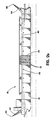
- FIGURE 2a is a side elevation view in section of a ship equipped in accordance with the teachings of the ship based system for compressed natural gas transport.
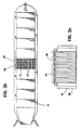
- FIGURE 2b is a top plan view in longitudinal section of the ship illustrated in FIGURE 2a.
- FIGURE 2c is an end elevation view in transverse section taken along section lines A-A of FIGURE 2b.
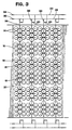
- FIGURE 3 is a detailed top plan view of a portion of the ship illustrated in FIGURE 2b.
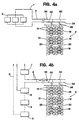
- FIGURE 4a is a schematic diagram of a loading arrangement for the ship based system for compressed natural gas transport.
- FIGURE 4b is a schematic diagram of an unloading arrangement for the ship based system for compressed natural gas transport.
-
- The preferred embodiment, a ship based system for compressed natural gas transport generally identified by
reference numeral 10, will now be described with reference to FIGURES 1 through 4b. - Referring to FIGURES 2a and 2b, a ship based system for compressed
natural gas transport 10 includes aship 12 having a plurality ofgas cylinders 14. The gas cylinders are designed to safely accept the pressure of CNG, which may range between 1000 to 5000 psi (approximately 6.89 to 34.47 MN/m2), to be set by optimization taking into account the cost of pressure vessels, ships, etc. and the physical properties of the gas. It is preferred that the values be in the range of 2500 to 3500 psi (approximately 17.23 to 24.13 MN/m2).Gas cylinders 14 are cylindrical steel pipes in 30 to 100 foot lengths (approximately 9.14 to 30.48 m). A preferred length is 70 feet (approximately 21.34 m) long. The pipes will be capped, typically, by the welding of forged steel domes on both ends. - The plurality of
gas cylinders 14 are configured into a plurality of compressedgas storage cells 16. Referring to FIGURE 3, each of compressedgas storage cells 16 consists of between 3 and 30gas cylinders 14 connected by acell manifold 18 to asingle control valve 20. Referring to FIGURES 2a and 2c,gas cylinders 14 are mounted vertically oriented, for ease of replacement, within ahold 22 ofship 12. The length ofcylinders 14 will typically be set so as to preserve the stability ofship 12. The holds 22 are covered with hatch covers 24 to keep out seawater in heavy weather, but also to facilitate cylinder changeout. Hatch covers 24 will have airtight seals to enable holds 22 to be flooded with an inert atmosphere at near ambient pressure. The holds 22 are serviced by a lowpressure manifold system 42, as shown in FIGURE 2a, to provide initial flood and subsequent maintenance of the inert gas atmosphere. - The present invention contemplates little or no refrigeration of the gas during the loading phase. Typically the only cooling involved will be to return the gas to near ambient temperature by means of conventional air or seawater cooling immediately after compression. However, the lower the temperature of the gas, the larger the quantity that can be stored in the
cylinders 14. Because of adiabatic expansion of the CNG during the delivery process. thesteel cylinders 14 will be cooled to some extent. It is desirable to preserve the coolness of this thermal mass of steel for its value in the next loading phase, in typically 1 to 3 days time. For this reason, referring to FIGURE 2c, both holds 22 and hatch covers 24 are covered with a layer ofinsulation 26. - Referring to FIGURE 3, a
high pressure manifold 28 is provided which includes avalve 30 adapted for connection to shore terminals. Alow pressure manifold 32 is provided including avalve 34 adapted for connection to shore terminals. Asubmanifold 36 extends between eachcontrol valve 20 to connect eachstorage cell 16 to bothhigh pressure manifold 28 andlow pressure manifold 32. A plurality ofvalves 38 control the flow of gas fromsubmanifold 36 intohigh pressure manifold 28. A plurality ofvalves 40 control the flow of gas fromsubmanifold 36 intolow pressure manifold 32. In the event that a storage cell must be rapidly blown down when theship 12 is at sea, the gas will be carried byhigh pressure manifold 28 to aventing boom 44 and thence to aflare 46, as illustrated in FIGURE 2a. If the engines of theship 10 are designed to bum natural gas, either the high or low pressure manifold will convey it from thecells 16. -
Ship 12, as described above, must be integrated as part of an overall transportation system with shore facilities. The overall operation of ship based system for compressednatural gas transport 10 will now be described with the aid of FIGURES 1, 4a, and 4b. FIGURE I is a flow chart that sets forth the step by step handling of the natural gas. Referring to FIGURE 1, natural gas is delivered to the system by a pipeline (1) at typically 500 to 700 psi (approximately 3.45 to 4.82 MN/m2). A portion of this gas can pass directly through the shipping terminal (3) to thelow pressure manifold 32 to raise a small number of thecells 16 to the pipeline pressure from their "empty" pressure of about 200 psi (approximately 1.38 MN/m2). Those cells are then switched to thehigh pressure manifold 28 and another small number of empty cells are opened to thelow pressure manifold 32. The larger portion of the pipeline gas is compressed to high pressure at the shipping point compression facility (2). Once the gas is compressed it is delivered via a marine terminal and manifold system (3) to thehigh pressure manifold 28 on the CNG Carrier (4) (which in this case is ship 12), whence it brings thosecells 16 connected to it up to close to full design pressure (e.g., 2700 psi) (approximately 18.61 MN/m2). This process of opening and switching groups of cells, one after the other, is referred to as a "rolling fill." The beneficial effect is that the compressor (2) is compressing to its full design pressure almost all the time which makes for maximum efficiency . The CNG Carrier (4) carries the compressed gas to the delivery terminal (5). The high pressure gas is then discharged to a decompression facility (6) where the gas pressure is reduced to the pressure required by the receiving pipeline (9). Optionally the decompression energy of the high pressure gas can be used to power a cryogenic unit to generate a small portion of LPG, gas liquids and LNG (6) which can be stored and the gas liquids and LNG regassified later (8) as required to maintain gas service to the market At some point during the delivery of the gas, the gas pressure on the CNG Carrier will be insufficient to deliver gas at the rate and pressure required. At this time the gas will be sent to the delivery point compression facility (7) where it will be compressed to the pipeline (9) required pressure. If the above process is carried out with small groups ofcells 16 at a time, a "rolling empty" results which will, as above, provide the compressor (7) with the design back pressure most of the time and hence use it with maximum efficiency. - Whether or not an LNG storage facility has been added, it is preferred that there shall be a sufficient number of CNG carrier ships 12 of appropriate capacity and speed so operated that there will be a ship moored and discharging at the delivery point at all times, except under upset conditions. Operated in this manner, the CNG ship system will provide essentially the same level of service as a natural gas pipeline. In an important alternative embodiment, the ship's manifolds and delivery compression station (7) can be so sized that the ship's cargo can be loaded in a relatively short time, say 2-8 hours, typically 4 hours, versus one-half to three days, typically one day normal unloading time. This alternative would permit a marine CNG project to supply peak-shaving fuel into a market already possessed of sufficient base load capacity.
- It will be appreciated that the embodiment provides an improvement in over water CNG transport that utilizes a ship having a plurality of gas cylinders. The gas pressure in the cylinders would, preferably, be in the range of 2000 psi to 3500 psi (approximately 13.79 to 24.13 MN/m2) when charged and in the range of 100 to 300 psi (approximately 0.69 to 2.07 MN/m2) when discharged. The gas cylinders are configured into a plurality of compressed gas storage cells. Each compressed gas storage cell consists of between 3 and 30 gas cylinders connected by a cell manifold to a single control valve.
- It will be apparent to one skilled in the art that modifications may be made to the illustrated embodiment within the scope of the invention as defined by the claims.
Claims (20)
- A system for compressed gas transport, said system (10) comprising:a ship (12);a plurality of compressed gas cylinders (14) constructed and arranged to be transported by said ship;a high pressure manifold (28), said high pressure manifold including means (30) adapted for connection to a shore terminal; anda low pressure manifold (32), said low pressure manifold including means (34) adapted for connection to a shore terminal; characterised by a plurality of gas storage cells (16) each comprising between 3 and 30 said gas cylinders connected by a cell manifold (18) to a single cell control valve (20); by a plurality of submanifolds (36) each connecting said high pressure manifold and said low pressure manifold to each single cell control valve of a respective plurality of said cell control valves; and by a plurality of valve means for selectively controlling the flow of compressed gas from said submanifolds through said high and low pressure manifolds.
- A system as claimed in claim 1, wherein said ship has cargo holds (22) and said gas cylinders (14) are vertically oriented within said cargo holds.
- A system as claimed in claim 2, further including a substantially airtight hatch cover (24) for each of said cargo holds; and means (42) for supplying an inert gas to each of said cargo holds; whereby, each of said cargo holds can be flooded with an inert atmosphere of said inert gas.
- A system as claimed in claim 3, wherein said cargo holds and said substantially airtight hatch covers are thermally insulated.
- A system as claimed in claim 2, 3 or 4, further including gas leak detection equipment in each of said cargo holds; and means (44,46) for venting compressed gas from a leaking gas storage cell to atmosphere.
- A system as claimed in claim 5, wherein said means for venting compressed gas from a leaking gas storage cell to atmosphere includes a flare (46).
- A system as claimed in any one of the preceding claims, wherein each of said gas cylinders can contain compressed gas at from about 1,000 psi to about 5,000 psi (approximately 6.89 to 34.45 MN/m2).
- A system as claimed in any one of the preceding claims, wherein each of said compressed gas storage cells includes not less than 3 nor more than 30 of said gas cylinders.
- A system as claimed in any one of the preceding claims, wherein said gas cylinders are constructed from welded mild steel pipe with domed welded caps on each end.
- A system as claimed in any one of the preceding claims, wherein said compressed gas is natural gas.
- A system as claimed in claim 1, further including a shore based facility including compressor means.
- A system as claimed in claim 1, further including a shore terminal (5) for receiving compressed gas from said ship, wherein said shore terminal includes a cryogenic unit for converting a portion of said compressed gas received from said ship into liquefied gas.
- A system as claimed in claim 1, further including a shore terminal for receiving compressed gas discharged from said high pressure manifold of said ship and from said low pressure manifold of said ship and for supplying said compressed gas to a gas transmission pipeline, said shore terminal including unloading compressor means for compressing said gas received from said low pressure manifold prior to supplying said gas from said low pressure manifold to said pipeline.
- A system as claimed in claim 13, wherein said high pressure manifold and said low pressure manifold and said unloading compressor means are sized and constructed to permit substantially complete unloading of said ship within about 8 hours.
- A method for filling a ship-borne storage system (10) with compressed gas from an upstream shore based facility adapted to supply compressed gas from a supply pipeline to said ship at a first pressure corresponding substantially to supply pipeline pressure and at a second pressure which is greater than the first pressure, said ship-borne storage system including a low pressure manifold (32) adapted to receive gas at said first pressure from said shore based facility, a high pressure manifold (28) adapted to receive gas at said second pressure from said shore based facility and a plurality of gas storage cells (16), each of said gas storage cells including a plurality of interconnected gas cylinders (14), said method comprising the steps of:(a) connecting a first gas storage cell to said low pressure manifold;(b) conducting a portion of the compressed gas at the first pressure through the low pressure manifold to partially fill the first gas storage cell to substantially the first pressure;(c) isolating the first gas storage cell from the low pressure manifold;(d) connecting the first gas storage cell to the high pressure manifold;(e) conducting a portion of the compressed gas at the second pressure through the high pressure manifold to the first gas storage cell to fill first gas storage cell to substantially the second pressure;(f) connecting a second gas storage cell to the low pressure manifold; and(g) continuing said steps until substantially all of the gas storage cells are filled with compressed gas at substantially the second pressure.
- A method for discharging compressed gas from a ship-borne storage system (10) to a downstream shore facility adapted to further supply such compressed gas at pipeline pressure to a downstream gas pipeline, said shore facility including decompression means (6) for decompressing compressed gas received from said ship prior to supplying the compressed gas to the downstream pipeline, said ship-borne storage system including a high pressure manifold (28) adapted to discharge gas to said decompression means, a low pressure manifold (32) adapted to discharge gas to said compressor means and a plurality of gas storage cells (16), each of said gas storage cells including a plurality of interconnected gas cylinders (14) containing compressed gas at a ship-borne pressure which is substantially greater than said downstream pipeline pressure, said method comprising the steps of:(a) connecting a first gas storage cell to said high pressure manifold;(b) discharging a portion of said compressed gas from said first gas storage cell through said high pressure manifold to said decompression means;(c) isolating said first gas storage cell from said high pressure manifold;(d) connecting said first gas storage cell to said low pressure manifold;(e) conducting a portion of said compressed gas from said first gas storage cell through said low pressure manifold to said compressor means;(f) connecting a second gas storage cell to said high pressure manifold; and(g) continuing said steps until substantially all of said gas storage cells have discharged a portion of their compressed gas through each of said high pressure and low pressure manifolds.
- A method as claimed in claim 16, wherein said compressed gas is allowed to expand adiabatically during said ship discharging process.
- A method as claimed in claim 17, wherein said adiabatic expansion of said compressed gas is used to chill said plurality of gas cylinders; and additionally, including the step of maintaining the chill of said gas cylinders until said chilled gas cylinders are refilled with compressed gas.
- A method as claimed in claim 16,17 or 18, wherein said shore facility also includes additional compressor means for converting a portion of said compressed gas into liquefied gas and storage means for storing said liquefied gas and additionally including the step of directing a portion of said compressed gas discharged from said high pressure manifold to power said additional compressor means.
- A method as claimed in claim 19, wherein said compressed gas is natural gas and said liquefied gas is LNG.
Applications Claiming Priority (3)
| Application Number | Priority Date | Filing Date | Title |
|---|---|---|---|
| US55008095A | 1995-10-30 | 1995-10-30 | |
| US550080 | 1995-10-30 | ||
| PCT/IB1996/001274 WO1997016678A1 (en) | 1995-10-30 | 1996-10-28 | Ship based system for compressed natural gas transport |
Publications (2)
| Publication Number | Publication Date |
|---|---|
| EP0858572A1 EP0858572A1 (en) | 1998-08-19 |
| EP0858572B1 true EP0858572B1 (en) | 2003-12-10 |
Family
ID=24195657
Family Applications (1)
| Application Number | Title | Priority Date | Filing Date |
|---|---|---|---|
| EP96935299A Expired - Lifetime EP0858572B1 (en) | 1995-10-30 | 1996-10-28 | Ship based system for compressed natural gas transport |
Country Status (29)
| Country | Link |
|---|---|
| US (1) | US5803005A (en) |
| EP (1) | EP0858572B1 (en) |
| JP (1) | JP4927239B2 (en) |
| KR (1) | KR100458142B1 (en) |
| CN (1) | CN1062062C (en) |
| AR (1) | AR004247A1 (en) |
| AT (1) | ATE256268T1 (en) |
| AU (1) | AU716813B2 (en) |
| BR (1) | BR9607554A (en) |
| CA (1) | CA2198358C (en) |
| CO (1) | CO4930017A1 (en) |
| DE (1) | DE69631062T2 (en) |
| DK (1) | DK0858572T3 (en) |
| EG (1) | EG22042A (en) |
| ES (1) | ES2210395T3 (en) |
| IL (1) | IL123547A0 (en) |
| MX (1) | MX9702712A (en) |
| MY (1) | MY126339A (en) |
| NO (1) | NO314274B1 (en) |
| NZ (1) | NZ320555A (en) |
| PE (1) | PE34198A1 (en) |
| PL (1) | PL182179B1 (en) |
| PT (1) | PT858572E (en) |
| RU (1) | RU2145689C1 (en) |
| SA (1) | SA97170797B1 (en) |
| TR (1) | TR199800689T1 (en) |
| TW (1) | TW372223B (en) |
| WO (1) | WO1997016678A1 (en) |
| ZA (1) | ZA969094B (en) |
Cited By (2)
| Publication number | Priority date | Publication date | Assignee | Title |
|---|---|---|---|---|
| EP2686602B1 (en) | 2011-03-16 | 2015-06-17 | Messer GasPack GmbH | Arrangement for storing and extracting compressed gas |
| WO2023167592A1 (en) * | 2022-03-02 | 2023-09-07 | Equinor Energy As | Ammonia storage |
Families Citing this family (72)
| Publication number | Priority date | Publication date | Assignee | Title |
|---|---|---|---|---|
| US5839383A (en) * | 1995-10-30 | 1998-11-24 | Enron Lng Development Corp. | Ship based gas transport system |
| BR9607554A (en) * | 1995-10-30 | 1998-07-07 | Enron Lng Dev Corp | Ship-based system for transporting compressed natural gas |
| ATE224405T1 (en) * | 1996-05-01 | 2002-10-15 | Ineos Silicas Ltd | POROUS, INORGANIC CATALYST SUPPORT |
| JPH10115570A (en) * | 1996-10-11 | 1998-05-06 | Teisan Kk | Inspection apparatus for leak of a plurality of gas containers |
| TW359736B (en) * | 1997-06-20 | 1999-06-01 | Exxon Production Research Co | Systems for vehicular, land-based distribution of liquefied natural gas |
| DZ2528A1 (en) * | 1997-06-20 | 2003-02-01 | Exxon Production Research Co | Container for the storage of pressurized liquefied natural gas and a process for the transport of pressurized liquefied natural gas and natural gas treatment system to produce liquefied natural gas under pressure. |
| TW436597B (en) * | 1997-12-19 | 2001-05-28 | Exxon Production Research Co | Process components, containers, and pipes suitable for containign and transporting cryogenic temperature fluids |
| DE19846288A1 (en) * | 1998-10-08 | 2000-04-20 | Messer Griesheim Gmbh | Production of gas mixtures in large quantities |
| MY115510A (en) | 1998-12-18 | 2003-06-30 | Exxon Production Research Co | Method for displacing pressurized liquefied gas from containers |
| TW446800B (en) | 1998-12-18 | 2001-07-21 | Exxon Production Research Co | Process for unloading pressurized liquefied natural gas from containers |
| US6112528A (en) * | 1998-12-18 | 2000-09-05 | Exxonmobil Upstream Research Company | Process for unloading pressurized liquefied natural gas from containers |
| US6460721B2 (en) | 1999-03-23 | 2002-10-08 | Exxonmobil Upstream Research Company | Systems and methods for producing and storing pressurized liquefied natural gas |
| CA2299755C (en) | 1999-04-19 | 2009-01-20 | Trans Ocean Gas Inc. | Natural gas composition transport system and method |
| US6412508B1 (en) | 2000-01-12 | 2002-07-02 | Resource Llc | Natural gas pipe storage facility |
| US6240868B1 (en) | 2000-02-04 | 2001-06-05 | Wild Rose Holdings Ltd. | Containment structure and method of manufacture thereof |
| US6584781B2 (en) | 2000-09-05 | 2003-07-01 | Enersea Transport, Llc | Methods and apparatus for compressed gas |
| US6994104B2 (en) * | 2000-09-05 | 2006-02-07 | Enersea Transport, Llc | Modular system for storing gas cylinders |
| AU783543B2 (en) * | 2000-10-17 | 2005-11-10 | Steven Campbell | Natural gas composition transport system and method |
| JP2002120792A (en) * | 2000-10-18 | 2002-04-23 | Campbell Steven | Device and method for transporting natural gas composition |
| FR2815695B1 (en) * | 2000-10-19 | 2003-01-31 | Air Liquide | PRESSURE GAS STORAGE DEVICE |
| NO313846B1 (en) * | 2001-02-13 | 2002-12-09 | Knutsen Oas Shipping As | Apparatus and method for attaching pressure tanks |
| IL157876A0 (en) * | 2001-03-21 | 2004-03-28 | Williams Energy Marketing & Tr | Containment structure and method of manufacture thereof |
| NO315214B1 (en) * | 2001-04-03 | 2003-07-28 | Knutsen Oas Shipping As | Method and device for petroleum loading. (Evaporative tank over tire and compressors with pressure storage tanks) |
| NO315723B1 (en) * | 2001-07-09 | 2003-10-13 | Statoil Asa | System and method for transporting and storing compressed natural gas |
| NO20015962D0 (en) * | 2001-12-06 | 2001-12-06 | Knutsen Oas Shipping As | Cargo compartment |
| US7147124B2 (en) * | 2002-03-27 | 2006-12-12 | Exxon Mobil Upstream Research Company | Containers and methods for containing pressurized fluids using reinforced fibers and methods for making such containers |
| WO2003089836A1 (en) * | 2002-04-19 | 2003-10-30 | Mannesmannröhren-Werke Ag | Pressurised container for storing gaseous media under pressure |
| WO2004000636A2 (en) * | 2002-06-25 | 2003-12-31 | Smith Eric N | Method and apparatus for transporting compressed natural gas in a marine environment |
| US6722399B1 (en) | 2002-10-29 | 2004-04-20 | Transcanada Pipelines Services, Ltd. | System and method for unloading compressed gas |
| US6840709B2 (en) | 2003-01-13 | 2005-01-11 | David Fred Dahlem | Distributed natural gas storage system(s) using oil & gas & other well(s) |
| NO319876B1 (en) * | 2003-07-09 | 2005-09-26 | Statoil Asa | System for storing or transporting compressed gas on a liquid structure |
| US20050005831A1 (en) * | 2003-07-11 | 2005-01-13 | Geoexplorers International, Inc. | Shipboard system for transportation of natural gas in zeolites |
| NO323121B1 (en) * | 2003-07-22 | 2007-01-08 | Knutsen Oas Shipping As | Method and apparatus for securing a vessel's cargo area against overpressure |
| FI116972B (en) * | 2004-02-09 | 2006-04-28 | Waertsilae Finland Oy | Barge arrangement, barge unit and tug unit |
| NO20053844L (en) * | 2005-07-06 | 2007-01-08 | Compressed Energy Technology A | Compressed natural gas transport device |
| DE102005057451A1 (en) | 2005-12-01 | 2007-06-14 | Tge Gas Engineering Gmbh | Device for storing a tank in a ship |
| FI123864B (en) * | 2006-06-19 | 2013-11-29 | Waertsilae Finland Oy | Watercraft |
| KR100779779B1 (en) | 2006-07-28 | 2007-11-27 | 대우조선해양 주식회사 | Handling of LNG Regasification Marine Offshore Regasification Systems for Ships |
| EP2160539B1 (en) | 2007-03-02 | 2017-05-03 | Enersea Transport LLC | Apparatus and method for flowing compressed fluids into and out of containment |
| JP5403900B2 (en) * | 2007-11-16 | 2014-01-29 | 三菱重工業株式会社 | Liquefied gas carrier |
| BRPI0800985A2 (en) * | 2008-04-10 | 2011-05-31 | Internat Finance Consultant Ltda | integrated process for obtaining gnl and gnc and their energy suitability, flexibly integrated system for carrying out said process and uses of gnc obtained by said process |
| NO331660B1 (en) * | 2008-11-19 | 2012-02-20 | Moss Maritime As | Device for liquid production of LNG and method for converting an LNG ship to such device |
| FI121876B (en) * | 2010-04-09 | 2011-05-31 | Waertsilae Finland Oy | Procedure for operating a watercraft using LNG as fuel and watercraft |
| GB2481983A (en) * | 2010-07-12 | 2012-01-18 | Hart Fenton & Co Ltd | A ship including a gas tank room |
| US20120012225A1 (en) * | 2010-07-19 | 2012-01-19 | Marc Moszkowski | Method of filling CNG tanks |
| MX373961B (en) | 2010-10-12 | 2020-07-13 | Seaone Holdings Llc | IMPROVED METHODS FOR THE STORAGE AND TRANSPORTATION OF NATURAL GAS IN LIQUID SOLVENTS. |
| KR101130658B1 (en) * | 2010-10-18 | 2012-04-02 | 대우조선해양 주식회사 | LNG Storage Vessel Carrier |
| US8375876B2 (en) | 2010-12-04 | 2013-02-19 | Argent Marine Management, Inc. | System and method for containerized transport of liquids by marine vessel |
| EP2788253A1 (en) * | 2011-12-05 | 2014-10-15 | Blue Wave Co S.A. | Natural gas power generator for cng vessel |
| CN104114929A (en) * | 2011-12-05 | 2014-10-22 | 蓝波股份有限公司 | System for containing and transporting compressed natural gas in verifiable cylindrical containment units combined into modules |
| UA101584C2 (en) * | 2012-03-19 | 2013-04-10 | Абдул Карим Хамдо | Vessel for transportation of compressed gas |
| WO2014086413A1 (en) | 2012-12-05 | 2014-06-12 | Blue Wave Co S.A. | Integrated and improved system for sea transportation of compressed natural gas in vessels, including multiple treatment steps for lowering the temperature of the combined cooling and chilling type |
| WO2014086414A1 (en) * | 2012-12-05 | 2014-06-12 | Blue Wave Co S.A. | Dual-fuel feed circuit system using compressed natural gas for dual-feed converted ship engines, and integration thereof in a cng marine transportation system |
| CN104110573B (en) * | 2013-04-18 | 2017-09-26 | 气体科技能源概念公司 | It is a kind of to be used to supply natural gas to the system and fuel system of thermal spraying apparatus |
| RU2536755C1 (en) * | 2013-07-16 | 2014-12-27 | Общество с ограниченной ответственностью "Газпром трансгаз Екатеринбург" | Compressed natural gas filling method |
| US20160159450A1 (en) * | 2013-07-22 | 2016-06-09 | Daewoo Ship Building & Marine Engineering Co., Ltd | Floating marine structure and method for controlling temperature thereof |
| BR102013025684A2 (en) * | 2013-10-04 | 2015-08-25 | Pelz Construtores Associados Ltda | Method for the transport of natural gas composed of pneumatic capsules and said pneumatic capsule |
| US9759379B2 (en) | 2014-05-15 | 2017-09-12 | Sea Ng Corporation | Gas storage structure and method of manufacture |
| TW201607839A (en) | 2014-06-11 | 2016-03-01 | 希恩季股份有限公司 | Ship for gas storage and transport |
| US9481430B2 (en) | 2014-09-08 | 2016-11-01 | Elwha, Llc | Natural gas transport vessel |
| CN105270569B (en) * | 2015-06-23 | 2018-09-14 | 石家庄安瑞科气体机械有限公司 | A kind of safe and efficient cargo ship gas goods systems of CNG |
| FR3054872B1 (en) * | 2016-08-02 | 2018-08-17 | Gaztransport Et Technigaz | SEALED WALL STRUCTURE |
| EA201990460A1 (en) * | 2016-08-12 | 2019-07-31 | Гев Текнолоджиз Пти. Лтд | GAS STORAGE AND TRANSPORTATION DEVICE |
| JP6738761B2 (en) * | 2017-04-13 | 2020-08-12 | 三菱造船株式会社 | Ship |
| WO2018223116A1 (en) * | 2017-06-02 | 2018-12-06 | Chester Lng, Llc | Mobile storage and transportation of compressed natural gas |
| US10752324B2 (en) | 2018-12-31 | 2020-08-25 | Gev Technologies Pty. Ltd. | Pipe containment system for ships with spacing guide |
| KR20210118804A (en) * | 2019-02-05 | 2021-10-01 | 닛키 글로벌 가부시키가이샤 | processing plant |
| RU2725572C1 (en) * | 2019-11-05 | 2020-07-02 | Федеральное государственное унитарное предприятие "Российский Федеральный ядерный центр - Всероссийский научно-исследовательский институт экспериментальной физики" (ФГУП "РФЯЦ-ВНИИЭФ") | Method and ship system for compressed natural gas transportation |
| GB2598781B (en) * | 2020-09-14 | 2023-03-01 | Equinor Energy As | A method and vessel for transporting a semi-stable oil product |
| AU2021394134A1 (en) | 2020-12-11 | 2023-07-13 | Global Hydrogen Ventures Pty Ltd | Apparatus for gas storage and transport |
| GB2616635B (en) * | 2022-03-15 | 2024-06-05 | Equinor Energy As | A method of storing ethane |
| NO349611B1 (en) * | 2023-11-06 | 2026-03-09 | Knutsen Nyk Carbon Carriers As | A storage and transportation tank assembly for products at elevated pressures, and an associated system |
Family Cites Families (26)
| Publication number | Priority date | Publication date | Assignee | Title |
|---|---|---|---|---|
| US2411235A (en) * | 1943-02-11 | 1946-11-19 | Linde Air Prod Co | Apparatus and method for filling gas storage cylinders |
| US2491103A (en) * | 1946-01-10 | 1949-12-13 | Int Register Co | Clock |
| US2721529A (en) * | 1951-09-24 | 1955-10-25 | Norsk Hydro Elektrisk | Arrangement in tankers for transportation of liquids under pressure |
| US3232725A (en) * | 1962-07-25 | 1966-02-01 | Vehoc Corp | Method of storing natural gas for transport |
| CA788175A (en) * | 1963-12-20 | 1968-06-25 | D. Lewis John | Method and apparatus for handling natural gas |
| DE1233887B (en) * | 1963-12-31 | 1967-02-09 | Linde Ag | Pressurized gas filling level for filling pressurized gas bottles for at least two different filling pressures |
| FR1452058A (en) * | 1965-05-05 | 1966-09-09 | Conduites Immergees | New process for carrying out the maritime transport of gaseous hydrocarbons and new devices for implementing this process |
| DE1506270A1 (en) * | 1966-03-28 | 1969-06-19 | Linde Ag | Tanker for low-boiling liquid gases |
| FR2135575B1 (en) * | 1971-05-05 | 1973-07-13 | Liquid Gas Anlagen Union | |
| US3830180A (en) * | 1972-07-03 | 1974-08-20 | Litton Systems Inc | Cryogenic ship containment system having a convection barrier |
| DE2237699A1 (en) * | 1972-07-31 | 1974-02-21 | Linde Ag | CONTAINER SYSTEM FOR STORAGE AND / OR TRANSPORT LOW-BOILING LIQUID GASES |
| US4139019A (en) * | 1976-01-22 | 1979-02-13 | Texas Gas Transport Company | Method and system for transporting natural gas to a pipeline |
| JPS52120411A (en) * | 1976-04-02 | 1977-10-08 | Nippon Steel Corp | Highly pressurized natural gas trnsportation method |
| JPS584240B2 (en) * | 1977-10-07 | 1983-01-25 | 日立造船株式会社 | Low-temperature liquefied gas storage base |
| US4213476A (en) * | 1979-02-12 | 1980-07-22 | Texas Gas Transport Company | Method and system for producing and transporting natural gas |
| US4380242A (en) * | 1979-10-26 | 1983-04-19 | Texas Gas Transport Company | Method and system for distributing natural gas |
| NO148481C (en) * | 1980-07-08 | 1983-10-19 | Moss Rosenberg Verft As | PROCEDURE FOR TRANSPORTING OIL AND GAS UNDER HIGH PRESSURE IN TANKER ON BOARD OF A SHIP |
| CA1211702A (en) * | 1983-06-27 | 1986-09-23 | Don A. Bresie | Method and system for producing natural gas from offshore wells |
| US4715721A (en) * | 1985-07-19 | 1987-12-29 | Halliburton Company | Transportable integrated blending system |
| US4846088A (en) * | 1988-03-23 | 1989-07-11 | Marine Gas Transport, Ltd. | System for transporting compressed gas over water |
| SU1631225A1 (en) * | 1988-07-11 | 1991-02-28 | Всесоюзный научно-исследовательский и конструкторско-технологический институт компрессорного машиностроения | Gas supplying system for transport units |
| JPH02175393A (en) * | 1988-12-27 | 1990-07-06 | Mitsubishi Heavy Ind Ltd | Unloading method for lng ship |
| US5365980A (en) * | 1991-05-28 | 1994-11-22 | Instant Terminalling And Ship Conversion, Inc. | Transportable liquid products container |
| RU2035004C1 (en) * | 1992-09-18 | 1995-05-10 | Центральный научно-исследовательский институт им.акад.А.Н.Крылова | Reservoir for transporting and storing natural hard to liquify gases |
| JPH07119893A (en) * | 1993-10-27 | 1995-05-12 | Chiyoda Corp | Control method for low temperature liquefied gas piping |
| BR9607554A (en) * | 1995-10-30 | 1998-07-07 | Enron Lng Dev Corp | Ship-based system for transporting compressed natural gas |
-
1996
- 1996-10-28 BR BR9607554A patent/BR9607554A/en not_active IP Right Cessation
- 1996-10-28 AU AU72805/96A patent/AU716813B2/en not_active Expired
- 1996-10-28 ES ES96935299T patent/ES2210395T3/en not_active Expired - Lifetime
- 1996-10-28 CA CA002198358A patent/CA2198358C/en not_active Expired - Lifetime
- 1996-10-28 MX MX9702712A patent/MX9702712A/en unknown
- 1996-10-28 RU RU98110263/12A patent/RU2145689C1/en active
- 1996-10-28 EP EP96935299A patent/EP0858572B1/en not_active Expired - Lifetime
- 1996-10-28 PL PL96326938A patent/PL182179B1/en unknown
- 1996-10-28 NZ NZ320555A patent/NZ320555A/en not_active IP Right Cessation
- 1996-10-28 CN CN96191260A patent/CN1062062C/en not_active Expired - Lifetime
- 1996-10-28 AT AT96935299T patent/ATE256268T1/en active
- 1996-10-28 KR KR1019970702123A patent/KR100458142B1/en not_active Expired - Lifetime
- 1996-10-28 JP JP51720097A patent/JP4927239B2/en not_active Expired - Lifetime
- 1996-10-28 DE DE69631062T patent/DE69631062T2/en not_active Expired - Lifetime
- 1996-10-28 TR TR1998/00689T patent/TR199800689T1/en unknown
- 1996-10-28 IL IL12354796A patent/IL123547A0/en not_active IP Right Cessation
- 1996-10-28 WO PCT/IB1996/001274 patent/WO1997016678A1/en not_active Ceased
- 1996-10-28 DK DK96935299T patent/DK0858572T3/en active
- 1996-10-28 PT PT96935299T patent/PT858572E/en unknown
- 1996-10-29 MY MYPI96004486A patent/MY126339A/en unknown
- 1996-10-29 ZA ZA9609094A patent/ZA969094B/en unknown
- 1996-10-30 EG EG95896A patent/EG22042A/en active
- 1996-10-31 CO CO96057633A patent/CO4930017A1/en unknown
- 1996-10-31 AR ARP960104985A patent/AR004247A1/en unknown
- 1996-10-31 PE PE1996000757A patent/PE34198A1/en not_active Application Discontinuation
- 1996-12-04 TW TW085114957A patent/TW372223B/en not_active IP Right Cessation
-
1997
- 1997-04-08 SA SA97170797A patent/SA97170797B1/en unknown
- 1997-06-30 US US08/885,292 patent/US5803005A/en not_active Expired - Lifetime
-
1998
- 1998-03-25 NO NO19981347A patent/NO314274B1/en not_active IP Right Cessation
Cited By (2)
| Publication number | Priority date | Publication date | Assignee | Title |
|---|---|---|---|---|
| EP2686602B1 (en) | 2011-03-16 | 2015-06-17 | Messer GasPack GmbH | Arrangement for storing and extracting compressed gas |
| WO2023167592A1 (en) * | 2022-03-02 | 2023-09-07 | Equinor Energy As | Ammonia storage |
Also Published As
Similar Documents
| Publication | Publication Date | Title |
|---|---|---|
| CA2198358C (en) | Ship based system for compressed natural gas transport | |
| MXPA97002712A (en) | System based on boat for transport of natural gas comprim | |
| EP0946387B1 (en) | Ship based gas transport system | |
| CA2419956C (en) | Methods and apparatus for compressed gas | |
| EP2983981B1 (en) | Systems and methods for floating dockside liquefaction of natural gas | |
| US20020174662A1 (en) | Method and apparatus for offshore LNG regasification | |
| RU2589811C2 (en) | Vessel for transportation of compressed gas | |
| KR20140113933A (en) | System and method for loading, storing and offloading natural gas from ships | |
| US7240498B1 (en) | Method to provide inventory for expedited loading, transporting, and unloading of compressed natural gas | |
| US7240499B1 (en) | Method for transporting compressed natural gas to prevent explosions | |
| US6964180B1 (en) | Method and system for loading pressurized compressed natural gas on a floating vessel | |
| AU783543B2 (en) | Natural gas composition transport system and method | |
| TH30955A (en) | A system for transporting compressed natural gas primarily using ships. |
Legal Events
| Date | Code | Title | Description |
|---|---|---|---|
| PUAI | Public reference made under article 153(3) epc to a published international application that has entered the european phase |
Free format text: ORIGINAL CODE: 0009012 |
|
| 17P | Request for examination filed |
Effective date: 19980403 |
|
| AK | Designated contracting states |
Kind code of ref document: A1 Designated state(s): AT BE CH DE DK ES FI FR GB GR IE IT LI LU MC NL PT SE |
|
| 17Q | First examination report despatched |
Effective date: 20000414 |
|
| RAP1 | Party data changed (applicant data changed or rights of an application transferred) |
Owner name: WILLIAMS ENERGY MARKETING AND TRADING COMPANY |
|
| GRAH | Despatch of communication of intention to grant a patent |
Free format text: ORIGINAL CODE: EPIDOS IGRA |
|
| GRAS | Grant fee paid |
Free format text: ORIGINAL CODE: EPIDOSNIGR3 |
|
| GRAA | (expected) grant |
Free format text: ORIGINAL CODE: 0009210 |
|
| AK | Designated contracting states |
Kind code of ref document: B1 Designated state(s): AT BE CH DE DK ES FI FR GB GR IE IT LI LU MC NL PT SE |
|
| REG | Reference to a national code |
Ref country code: GB Ref legal event code: FG4D |
|
| REG | Reference to a national code |
Ref country code: CH Ref legal event code: EP |
|
| REG | Reference to a national code |
Ref country code: DK Ref legal event code: T3 |
|
| REG | Reference to a national code |
Ref country code: IE Ref legal event code: FG4D |
|
| REF | Corresponds to: |
Ref document number: 69631062 Country of ref document: DE Date of ref document: 20040122 Kind code of ref document: P |
|
| REG | Reference to a national code |
Ref country code: CH Ref legal event code: NV Representative=s name: BOVARD AG PATENTANWAELTE |
|
| REG | Reference to a national code |
Ref country code: SE Ref legal event code: TRGR |
|
| REG | Reference to a national code |
Ref country code: GR Ref legal event code: EP Ref document number: 20040400850 Country of ref document: GR |
|
| REG | Reference to a national code |
Ref country code: PT Ref legal event code: SC4A Free format text: AVAILABILITY OF NATIONAL TRANSLATION Effective date: 20040310 |
|
| REG | Reference to a national code |
Ref country code: ES Ref legal event code: FG2A Ref document number: 2210395 Country of ref document: ES Kind code of ref document: T3 |
|
| ET | Fr: translation filed | ||
| REG | Reference to a national code |
Ref country code: CH Ref legal event code: PFA Owner name: WILLIAMS POWER COMPANY, INC. Free format text: WILLIAMS ENERGY MARKETING AND TRADING COMPANY#ONE WILLIAMS CENTER SUITE 4100#TULSA, OKLAHOMA 74172 (US) -TRANSFER TO- WILLIAMS POWER COMPANY, INC.#ONE WILLIAMS CENTER SUITE 4100#TULSA, OK 74172 (US) |
|
| PLBE | No opposition filed within time limit |
Free format text: ORIGINAL CODE: 0009261 |
|
| STAA | Information on the status of an ep patent application or granted ep patent |
Free format text: STATUS: NO OPPOSITION FILED WITHIN TIME LIMIT |
|
| 26N | No opposition filed |
Effective date: 20040913 |
|
| NLT1 | Nl: modifications of names registered in virtue of documents presented to the patent office pursuant to art. 16 a, paragraph 1 |
Owner name: WILLIAMS POWER COMPANY, INC. |
|
| REG | Reference to a national code |
Ref country code: FR Ref legal event code: CD |
|
| REG | Reference to a national code |
Ref country code: PT Ref legal event code: PD4A Free format text: WILLIAMS POWER COMPANY, INC. US Effective date: 20050210 |
|
| REG | Reference to a national code |
Ref country code: ES Ref legal event code: PC2A |
|
| REG | Reference to a national code |
Ref country code: PT Ref legal event code: PC4A Owner name: SEA NG MANAGEMENT CORPORATION, CA Effective date: 20060525 |
|
| REG | Reference to a national code |
Ref country code: FR Ref legal event code: TP |
|
| REG | Reference to a national code |
Ref country code: CH Ref legal event code: PUE Owner name: SEA NG MANAGEMENT CORPORATION Free format text: WILLIAMS POWER COMPANY, INC.#ONE WILLIAMS CENTER SUITE 4100#TULSA, OK 74172 (US) -TRANSFER TO- SEA NG MANAGEMENT CORPORATION#750, 101 - 6TH AVENUE SW#CALGARY, ALBERTA T2P 3P4 (CA) Ref country code: CH Ref legal event code: PFA Owner name: SEA NG CORPORATION Free format text: SEA NG MANAGEMENT CORPORATION#750, 101 - 6TH AVENUE SW#CALGARY, ALBERTA T2P 3P4 (CA) -TRANSFER TO- SEA NG CORPORATION#750, 101 - 6TH AVENUE SW#CALGARY, ALBERTA T2P 3P4 (CA) |
|
| NLS | Nl: assignments of ep-patents |
Owner name: SEA NG MANAGEMENT CORPORATION Effective date: 20080519 |
|
| NLT1 | Nl: modifications of names registered in virtue of documents presented to the patent office pursuant to art. 16 a, paragraph 1 |
Owner name: SEA NG CORPORATION |
|
| REG | Reference to a national code |
Ref country code: ES Ref legal event code: PC2A |
|
| REG | Reference to a national code |
Ref country code: CH Ref legal event code: PFA Owner name: SEA NG CORPORATION Free format text: SEA NG CORPORATION#750, 101 6TH AVENUE SW#CALGARY, ALBERTA T2P 3P4 (CA) -TRANSFER TO- SEA NG CORPORATION#750, 101 6TH AVENUE SW#CALGARY, ALBERTA T2P 3P4 (CA) |
|
| PGFP | Annual fee paid to national office [announced via postgrant information from national office to epo] |
Ref country code: MC Payment date: 20120926 Year of fee payment: 17 |
|
| PGFP | Annual fee paid to national office [announced via postgrant information from national office to epo] |
Ref country code: LU Payment date: 20121031 Year of fee payment: 17 |
|
| PGFP | Annual fee paid to national office [announced via postgrant information from national office to epo] |
Ref country code: DK Payment date: 20121010 Year of fee payment: 17 |
|
| PGFP | Annual fee paid to national office [announced via postgrant information from national office to epo] |
Ref country code: IE Payment date: 20121010 Year of fee payment: 17 Ref country code: FI Payment date: 20121010 Year of fee payment: 17 Ref country code: BE Payment date: 20121018 Year of fee payment: 17 Ref country code: FR Payment date: 20121018 Year of fee payment: 17 Ref country code: CH Payment date: 20121012 Year of fee payment: 17 |
|
| PGFP | Annual fee paid to national office [announced via postgrant information from national office to epo] |
Ref country code: SE Payment date: 20121011 Year of fee payment: 17 Ref country code: ES Payment date: 20121031 Year of fee payment: 17 Ref country code: PT Payment date: 20120430 Year of fee payment: 17 |
|
| PGFP | Annual fee paid to national office [announced via postgrant information from national office to epo] |
Ref country code: NL Payment date: 20121010 Year of fee payment: 17 Ref country code: AT Payment date: 20120927 Year of fee payment: 17 |
|
| BERE | Be: lapsed |
Owner name: *SEA NG CORP. Effective date: 20131031 |
|
| REG | Reference to a national code |
Ref country code: PT Ref legal event code: MM4A Free format text: LAPSE DUE TO NON-PAYMENT OF FEES Effective date: 20140428 |
|
| REG | Reference to a national code |
Ref country code: NL Ref legal event code: V1 Effective date: 20140501 |
|
| REG | Reference to a national code |
Ref country code: DK Ref legal event code: EBP Effective date: 20131031 |
|
| PG25 | Lapsed in a contracting state [announced via postgrant information from national office to epo] |
Ref country code: MC Free format text: LAPSE BECAUSE OF NON-PAYMENT OF DUE FEES Effective date: 20131031 |
|
| REG | Reference to a national code |
Ref country code: CH Ref legal event code: PL |
|
| REG | Reference to a national code |
Ref country code: SE Ref legal event code: EUG |
|
| REG | Reference to a national code |
Ref country code: AT Ref legal event code: MM01 Ref document number: 256268 Country of ref document: AT Kind code of ref document: T Effective date: 20131028 |
|
| REG | Reference to a national code |
Ref country code: IE Ref legal event code: MM4A |
|
| PG25 | Lapsed in a contracting state [announced via postgrant information from national office to epo] |
Ref country code: CH Free format text: LAPSE BECAUSE OF NON-PAYMENT OF DUE FEES Effective date: 20131031 Ref country code: LI Free format text: LAPSE BECAUSE OF NON-PAYMENT OF DUE FEES Effective date: 20131031 |
|
| REG | Reference to a national code |
Ref country code: FR Ref legal event code: ST Effective date: 20140630 |
|
| PG25 | Lapsed in a contracting state [announced via postgrant information from national office to epo] |
Ref country code: SE Free format text: LAPSE BECAUSE OF NON-PAYMENT OF DUE FEES Effective date: 20131029 Ref country code: FR Free format text: LAPSE BECAUSE OF NON-PAYMENT OF DUE FEES Effective date: 20131031 Ref country code: PT Free format text: LAPSE BECAUSE OF NON-PAYMENT OF DUE FEES Effective date: 20140428 Ref country code: NL Free format text: LAPSE BECAUSE OF NON-PAYMENT OF DUE FEES Effective date: 20140501 Ref country code: FI Free format text: LAPSE BECAUSE OF NON-PAYMENT OF DUE FEES Effective date: 20131028 Ref country code: AT Free format text: LAPSE BECAUSE OF NON-PAYMENT OF DUE FEES Effective date: 20131028 |
|
| PG25 | Lapsed in a contracting state [announced via postgrant information from national office to epo] |
Ref country code: BE Free format text: LAPSE BECAUSE OF NON-PAYMENT OF DUE FEES Effective date: 20131031 |
|
| PG25 | Lapsed in a contracting state [announced via postgrant information from national office to epo] |
Ref country code: IE Free format text: LAPSE BECAUSE OF NON-PAYMENT OF DUE FEES Effective date: 20131028 Ref country code: DK Free format text: LAPSE BECAUSE OF NON-PAYMENT OF DUE FEES Effective date: 20131031 |
|
| REG | Reference to a national code |
Ref country code: ES Ref legal event code: FD2A Effective date: 20141107 |
|
| PG25 | Lapsed in a contracting state [announced via postgrant information from national office to epo] |
Ref country code: ES Free format text: LAPSE BECAUSE OF NON-PAYMENT OF DUE FEES Effective date: 20131029 |
|
| PG25 | Lapsed in a contracting state [announced via postgrant information from national office to epo] |
Ref country code: LU Free format text: LAPSE BECAUSE OF NON-PAYMENT OF DUE FEES Effective date: 20131028 |
|
| PGFP | Annual fee paid to national office [announced via postgrant information from national office to epo] |
Ref country code: GR Payment date: 20150929 Year of fee payment: 20 |
|
| PGFP | Annual fee paid to national office [announced via postgrant information from national office to epo] |
Ref country code: DE Payment date: 20151020 Year of fee payment: 20 Ref country code: GB Payment date: 20151028 Year of fee payment: 20 Ref country code: IT Payment date: 20151026 Year of fee payment: 20 |
|
| REG | Reference to a national code |
Ref country code: DE Ref legal event code: R071 Ref document number: 69631062 Country of ref document: DE |
|
| REG | Reference to a national code |
Ref country code: GB Ref legal event code: PE20 Expiry date: 20161027 |
|
| PG25 | Lapsed in a contracting state [announced via postgrant information from national office to epo] |
Ref country code: GB Free format text: LAPSE BECAUSE OF EXPIRATION OF PROTECTION Effective date: 20161027 |
|
| REG | Reference to a national code |
Ref country code: GR Ref legal event code: MA Ref document number: 20040400850 Country of ref document: GR Effective date: 20161029 |