EP0858564B1 - Method and device for the operation of a flexible drive mechanism - Google Patents
Method and device for the operation of a flexible drive mechanismInfo
- Publication number
- EP0858564B1 EP0858564B1 EP97924926A EP97924926A EP0858564B1 EP 0858564 B1 EP0858564 B1 EP 0858564B1 EP 97924926 A EP97924926 A EP 97924926A EP 97924926 A EP97924926 A EP 97924926A EP 0858564 B1 EP0858564 B1 EP 0858564B1
- Authority
- EP
- European Patent Office
- Prior art keywords
- wrap
- slip
- around
- output side
- drive
- Prior art date
- Legal status (The legal status is an assumption and is not a legal conclusion. Google has not performed a legal analysis and makes no representation as to the accuracy of the status listed.)
- Expired - Lifetime
Links
Images


Classifications
-
- F—MECHANICAL ENGINEERING; LIGHTING; HEATING; WEAPONS; BLASTING
- F16—ENGINEERING ELEMENTS AND UNITS; GENERAL MEASURES FOR PRODUCING AND MAINTAINING EFFECTIVE FUNCTIONING OF MACHINES OR INSTALLATIONS; THERMAL INSULATION IN GENERAL
- F16H—GEARING
- F16H55/00—Elements with teeth or friction surfaces for conveying motion; Worms, pulleys or sheaves for gearing mechanisms
- F16H55/32—Friction members
- F16H55/52—Pulleys or friction discs of adjustable construction
- F16H55/56—Pulleys or friction discs of adjustable construction of which the bearing parts are relatively axially adjustable
-
- F—MECHANICAL ENGINEERING; LIGHTING; HEATING; WEAPONS; BLASTING
- F16—ENGINEERING ELEMENTS AND UNITS; GENERAL MEASURES FOR PRODUCING AND MAINTAINING EFFECTIVE FUNCTIONING OF MACHINES OR INSTALLATIONS; THERMAL INSULATION IN GENERAL
- F16H—GEARING
- F16H61/00—Control functions within control units of change-speed- or reversing-gearings for conveying rotary motion ; Control of exclusively fluid gearing, friction gearing, gearings with endless flexible members or other particular types of gearing
- F16H61/66—Control functions within control units of change-speed- or reversing-gearings for conveying rotary motion ; Control of exclusively fluid gearing, friction gearing, gearings with endless flexible members or other particular types of gearing specially adapted for continuously variable gearings
- F16H61/662—Control functions within control units of change-speed- or reversing-gearings for conveying rotary motion ; Control of exclusively fluid gearing, friction gearing, gearings with endless flexible members or other particular types of gearing specially adapted for continuously variable gearings with endless flexible members
- F16H61/66254—Control functions within control units of change-speed- or reversing-gearings for conveying rotary motion ; Control of exclusively fluid gearing, friction gearing, gearings with endless flexible members or other particular types of gearing specially adapted for continuously variable gearings with endless flexible members controlling of shifting being influenced by a signal derived from the engine and the main coupling
Definitions
- the invention relates to an apparatus and a method to operate a belt transmission with the features the preamble of the independent claims.
- Gearboxes that are continuously variable in translation are in known various variations.
- belt transmission in which between a drive side connected to the vehicle and an output side connected to the vehicle wheels a belt, preferably a push link belt, or a belt or a chain, preferably a pull chain, is arranged.
- the drive or driven side generally has one each axially displaceable conical disk.
- Such systems are for example from EP, A1.0 451 887 or DE-OS 44 11 628 known.
- the efficiency of such gears depends largely on the contact pressure of the discs against the wrap element must be dimensioned so that surely no slip between the washers and the Wrapping element occurs. This contact pressure can, with a certain security surcharge, after the largest too transmitting moment. However, this creates in normal operation of the vehicle, i.e. with less Transmission torques, excessive friction and hydraulic Losses in the transmission.
- a slip control is, for example DE-OS 44 11 628 mentioned at the beginning. To such a slip control is the most accurate knowledge of the moments of slip. In DE-OS 44 11 628 among other things, proposed the speed of the Loop element to capture.
- the generic DE 44 40 278 C1 shows a determination for determination the rotational speed of the transmission medium in the Cone pulley sets of a continuously variable transmission by Detection of the individual links of the transmission medium.
- the object of the present invention is one simple and accurate detection of slip.
- the invention is based on one in its translation adjustable belt transmission with a Drive side and an output side.
- the belt serve to produce a in their slip behavior influenceable mechanical operative connection between the Drive and output side, with influencing agents are provided, by means of which the sling means slip can be influenced.
- the essence of the invention is that at least two Sensor units are provided which are in the range of Wrapping means and between the drive and one Output side are arranged.
- the signals of this Sensor units are then according to the invention Influencing agents for influencing the slip of the Belt means fed.
- the invention arranged sensor units it is possible in a simple manner to record the current slip very precisely and to Influence on slip.
- the belt means are in subdivided individual segments on the sensor units for establishing the mechanical operative connection between the Guide the drive and driven side past.
- the sensor units are then arranged such that the signals to the Represent sensor units passing segments.
- One of the sensor units is included arranged so that the signal to drive or Output side leading segments represented, while the other of the sensor units is arranged such that their Signal leading to the drive or driven side Represented segments.
- the drive side and / or the Output side at least one axially displaceable element have, which is essentially the shape of a conical disk has.
- At least one belt preferably a push link belt, or a belt or one Chain between disc pairs that drive and Represent output side, be clamped, the slip between the belt and the belt clamping disc pairs can be influenced.
- the influencing means are advantageously such designed that a geometric translation depending on the Difference between the two sensor signals is formed.
- the current slip can be determined first and second Speed detection means for detecting the speed of the Drive and / or driven side can be provided, the Output signals of these speed detection means Influencing agents are supplied.
- the influencer are then designed such that depending on the Output signals of this speed detection means a Speed ratio is determined. By means of a comparison between the geometric translation and the Speed ratio is based on the current slip Belt is closed.
- the influencing means can be designed such that the slip is regulated to a predeterminable value, whereby for Regulation of the slip the current slip with one predefinable setpoint is compared.
- the invention further relates to a method of operation one adjustable in its translation Belt transmission with one drive side and one Output side and with straps for manufacture a mechanical behavior that can be influenced in its slip behavior Active connection between the input and output side.
- the essence of the method according to the invention is that the parts leading to the drive side or output side the belt means and those from the drive side or Parts of the belt means leading away on the driven side be detected and the slippage of the belt is affected depending on the detected parts.
- FIG. 1 shows an overview block diagram with a schematic representation of the transmission, while FIG. 2 schematically represents the location of the sensor units.
- FIG. 3 discloses a flow chart of one in FIG. 4 block shown.
- Figures 5a, 5b and 5c shows schematically different configurations of the Umschlingungslementes.
- the above point 1 is by an electrohydraulic Gear ratio or primary speed control 10 realized.
- a band tension control 11 is used for point 2 used.
- the secondary pressure P s is used to adjust the belt tension and the primary pressure P p is used to adjust the transmission or primary speed.
- the engine speed N m speed sensor 12
- the output signals N in and N out of the sensor units S1 and S2 to be described are supplied to the block 11 for the purpose of belt tension control.
- a secondary pressure P S to be set is determined. This will be described in more detail below with reference to FIGS. 3 and 4.
- the gear ratio is changed by adjusting the active radii of the pulleys.
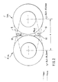
- the pulley sets are each made up of two truncated cones or conical disks that can be moved against each other. This is shown as a basic diagram in FIG. 2. Here, a sectional view is shown perpendicular to the axes of the truncated cones or conical disks, arrow 2 indicating the direction of rotation in normal forward operation of the vehicle.
- the looping element 9 is shown in two extreme translation settings u min and u max with lines and dots.
- the primary side of the engine is designated Prim and the side facing the vehicle wheels is designated Sec.
- the active radii for the wrapping element which in this example is supposed to be a thrust link belt 9, change.
- the radius at which the wrap element 9 acts on the primary side Prim that is, at which the force is transmitted, is designated r p , that on the secondary side Sec. R s .
- the length L r of the pusher belt 9 results in:
- the angle ⁇ between the pusher belt and the connecting line of the axes is (center distance a):
- L p L up + 2 * L ap
- L up denotes the looping length of the primary pulley
- L ap the path between the point of contact on the primary pulley and the sensor units S1 and S2.
- L p r p ( ⁇ + 2 ⁇ - tan ⁇ ) + a 2 cos ⁇
- N p and N s are the speeds of the primary and secondary sides (sensors 13, 14). If these two translations are not the same, the system works with a certain band slip.
- Block 112 to which the output signals N in and N out of sensors S1 and S2 are fed, is essential for the invention. As mentioned, these sensors S1 and S2 are designed such that they can count individual segments 502 or marks on the wrapping element. The segments or marks are attached to the wrapping element 9 at exactly constant distances. If the gearbox has the direction of rotation identified by the arrow 2 in FIG. 2, the sensor unit S1 counts the band segments N in or band markings arriving on the primary side and the sensor unit S2 counts the band segments N out or band markings running away from the primary side.
- FIG. 3 which shows the function of block 112 (FIG. 4)
- the current speed ratio u N is read in after step 301 in step 302.
- the number of segments or brands that are located on the primary side and on the secondary side is known. If these operating conditions exist (with the smallest and the largest gear ratio u min , u max ), the measurement can be started easily. For this reason, it is queried in step 303 whether such an operating condition with u min or u max is present.
- the operating state of maximum or minimum translation can also be determined by other parameters, for example by reading in the primary and / or secondary pressure.
- the starting value L min or L max is set as the starting value L start for the length L p of the band 9 on the primary side between the measuring points of the sensor units S1 and S2.
- step 305 the output signals N in and N out of the sensors S1 and S2 are then read in, which indicate the segments entering and leaving on the primary side.
- step 306 the current length L p of the tape 9 is determined on the primary side between the measuring points of the sensor units S1 and S2 in such a way that the number of incoming segments is added to the starting value L start and the number of outgoing segments is subtracted.
- step 307 the geometric translation u geo is determined from the value L p from the characteristic derived above (equations 7c and 8).
- step 303 If it is determined after a first start run in step 303 that no extreme transmission ratio u min or u max is set, then the output signals N in and N out of the sensors S1 and S2 are read in step 308, which are the segments entering and leaving the primary side specify.
- step 309 the current length L p of the strip 9 is determined on the primary side between the measuring points of the sensor units S1 and S2 in such a way that the number of incoming segments is added to the previously determined value L p and the number of outgoing segments is subtracted.
- the geometric translation is determined using block 307, which has already been described.
- a current value ⁇ B is calculated in block 113 and is calculated for the band slip ⁇ B (for example by forming a difference).
- This value ⁇ B is then compared in block 114 with a corresponding target value ⁇ B, whereupon, depending on this comparison, the belt tension (for example by setting the secondary pressure p s in the master-slave principle mentioned above) is set such that there is no slip (controller R, block 1142).
- the nominal value ⁇ B, should for the belt slip is, as mentioned at the beginning, determined taking into account the engine torque and the engine speed.
- a thrust link belt is known to consist of one Variety of segments 502 by a spring steel ring 503 are held together.
- Figure 5a shows a conventional push link belt 9 with individual segments 502, with a single segment 502 (without dashed Embodiment) can be seen in FIG. 5b.
- FIG. 5c Another way for an even clearer Detection of segments 502 is shown in FIG. 5c shown.
- every second segment 502 on the Band outside A extended by a few millimeters (see also dashed representation of segment 502 in the figure 5b).
- Such a marking is even easier detect as the gaps on the inside of the in the Figure 5a shown conventional tape.
- Sensor units S1 and S2 of course on the Be arranged outside of the band.
Description
Die Erfindung betrifft eine Vorrichtung bzw. ein Verfahren zum Betrieb eines Umschlingungsgetriebes mit den Merkmalen des Oberbegriffs der unabhängigen Ansprüche.The invention relates to an apparatus and a method to operate a belt transmission with the features the preamble of the independent claims.
Stufenlos in der Übersetzung veränderbare Getriebe sind in verschiedenen Variationen bekannt. Hierbei sind insbesondere die sogenannten Umschlingungsgetriebe zu erwähnen, bei denen zwischen einer mit dem Fahrzeug verbundenen Antriebsseite und einer mit den Fahrzeugrädern verbundenen Abtriebsseite ein Band, vorzugsweise ein Schubgliederband, oder ein Riemen oder eine Kette, vorzugsweise eine Zugkette, angeordnet ist. Die An- bzw. Abtriebseite weist dabei im allgemeinen je eine axial verschiebbare Kegelscheibe auf. Solche Systeme sind beispielsweise aus der EP,A1,0 451 887 oder der DE-OS 44 11 628 bekannt. Der Wirkungsgrad solcher Getriebe hängt maßgeblich davon ab, daß die Anpreßkraft der Scheiben gegen das Umschlingungselement so dimensioniert sein muß, daß sicher kein Schlupf zwischen den Scheiben und dem Umschlingungselement auftritt. Diese Anpreßkraft kann, mit einem gewissen Sicherheitszuschlag, nach dem größten zu übertragenden Moment dimensioniert sein. Dies erzeugt jedoch im Normalbetrieb des Fahrzeugs, also bei geringeren Übertragungsmomenten, zu hohe Reibkräfte und hydraulische Verluste im Getriebe.Gearboxes that are continuously variable in translation are in known various variations. Here are in particular to mention the so-called belt transmission, in which between a drive side connected to the vehicle and an output side connected to the vehicle wheels a belt, preferably a push link belt, or a belt or a chain, preferably a pull chain, is arranged. The drive or driven side generally has one each axially displaceable conical disk. Such systems are for example from EP, A1.0 451 887 or DE-OS 44 11 628 known. The efficiency of such gears depends largely on the contact pressure of the discs against the wrap element must be dimensioned so that surely no slip between the washers and the Wrapping element occurs. This contact pressure can, with a certain security surcharge, after the largest too transmitting moment. However, this creates in normal operation of the vehicle, i.e. with less Transmission torques, excessive friction and hydraulic Losses in the transmission.
Eine Möglichkeit, diese Situation zu verbessern, besteht darin, daß die Anpreßkraft dem momentanen Übertragungsmoment anzupassen. Die eingangs erwähnte EP,A1,0 451 887 steuert daher die Anpreßkraft abhängig von dem Motormoment. Eine weitere Möglichkeit besteht darin, die Anpreßkraft auf einen Wert zu reduzieren, der gerade ausreicht, um ein Durchrutschen bei dem aktuellen Übertragungsmoment sicher zu verhindern. Eine Schlupfregelung ist beispielsweise der eingangs erwähnten DE-OS 44 11 628 zu entnehmen. Zu solch einer Schlupfregelung ist die möglichst genaue Kenntnis des momenten Schlupfes notwendig. In der DE-OS 44 11 628 wird hierzu unter anderem vorgeschlagen, die Geschwindigkeit des Umschlingungselements zu erfassen.One way to improve this situation is in that the contact pressure is the instantaneous transmission torque adapt. The aforementioned EP, A1.0 451 887 controls hence the contact pressure depending on the engine torque. A Another option is to apply the contact pressure to one Reduce value just enough to get a Slipping safely at the current transmission torque prevent. A slip control is, for example DE-OS 44 11 628 mentioned at the beginning. To such a slip control is the most accurate knowledge of the moments of slip. In DE-OS 44 11 628 among other things, proposed the speed of the Loop element to capture.
Die gattungsgemäße DE 44 40 278 C1 zeigt eine Ermittlung zur Bestimmung der Umlaufgeschwindigkeit des Übertragungsmittels in den Kegelscheibensätzen eines stufenlosen Getriebes durch eine Detektion der einzelnen Glieder des Übertragungsmittels.The generic DE 44 40 278 C1 shows a determination for determination the rotational speed of the transmission medium in the Cone pulley sets of a continuously variable transmission by Detection of the individual links of the transmission medium.
Die DE 27 55 424 A1 zeigt die Ermittlung Getriebeschlupfs bei einem stufenlosen Getriebe dadurch, dass Markierungen auf dem Übertragungsmittels durch zwei Sensoren erfasst werden.DE 27 55 424 A1 shows the determination of gear slip in the case of a continuously variable transmission by markings detected on the transmission medium by two sensors become.
Die Aufgabe der vorliegenden Erfindung besteht in einer einfachen und genauen Erfassung des Schlupfes.The object of the present invention is one simple and accurate detection of slip.
Diese Aufgabe wird durch die Merkmale der unabhängigen Ansprüche gelöst. This task is characterized by the characteristics of the independent Claims resolved.
Wie erwähnt geht die Erfindung aus von einem in seiner Übersetzung verstellbaren Umschlingungsgetriebe mit einer Antriebsseite und einer Abtriebsseite. Die Umschlingungsmittel dienen zur Herstellung einer in ihrem Schlupfverhalten beeinflussbaren mechanischen Wirkverbindung zwischen der Antriebs- und Abtriebsseite, wobei Beeinflussungsmittel vorgesehen sind, mittels der der Schlupf der Umschlingungsmittel beeinflußt werden kann.As mentioned, the invention is based on one in its translation adjustable belt transmission with a Drive side and an output side. The belt serve to produce a in their slip behavior influenceable mechanical operative connection between the Drive and output side, with influencing agents are provided, by means of which the sling means slip can be influenced.
Der Kern der Erfindung besteht darin, daß wenigstens zwei Sensoreinheiten vorgesehen sind, die im Bereich der Umschlingungsmittel und zwischen der Antriebs- und einer Abtriebsseite angeordnet sind. Die Signale dieser Sensoreinheiten werden dann erfindungsgemäß den Beeinflussungsmitteln zur Beeinflussung des Schlupfes der Umschlingungsmittel zugeführt. Durch die erfindungsgemäß angeordneten Sensoreinheiten ist es in einfacher Weise möglich, den aktuellen Schlupf sehr genau zu erfassen und zur Schlupfbeeinflussung heranzuziehen.The essence of the invention is that at least two Sensor units are provided which are in the range of Wrapping means and between the drive and one Output side are arranged. The signals of this Sensor units are then according to the invention Influencing agents for influencing the slip of the Belt means fed. By the invention arranged sensor units, it is possible in a simple manner to record the current slip very precisely and to Influence on slip.
Erfindungsgemäß sind die Umschlingungsmittel in einzelne Segmente untergliedert, die an den Sensoreinheiten zur Herstellung der mechanischen Wirkverbindung zwischen der Antriebs- und Abtriebsseite vorbeiführen. Die Sensoreinheiten sind dann derart angeordnet, daß deren Signale die an den Sensoreinheiten vorbeiführenden Segmente repräsentieren.According to the invention, the belt means are in subdivided individual segments on the sensor units for establishing the mechanical operative connection between the Guide the drive and driven side past. The sensor units are then arranged such that the signals to the Represent sensor units passing segments.
Die eine der Sensoreinheiten ist dabei derart angeordnet, daß deren Signal die zur Antriebs- oder Abtriebsseite hinführenden Segmente repräsentiert, während die andere der Sensoreinheiten derart angeordnet ist, daß deren Signal die zur Antriebs- oder Abtriebsseite wegführenden Segmente repräsentiert. One of the sensor units is included arranged so that the signal to drive or Output side leading segments represented, while the other of the sensor units is arranged such that their Signal leading to the drive or driven side Represented segments.
Dabei ist es besonders vorteilhaft, die Sensoreinheiten derart anzuordnen, daß die Sensoreinheiten die Veränderungen der relativen Lage zwischen den Umschlingungsmitteln und den Sensoreinheiten erfassen. It is particularly advantageous to use the sensor units in this way to arrange that the sensor units the changes of relative position between the belt and the Detect sensor units.
Wie schon eingangs erwähnt kann die Antriebsseite und/oder die Abtriebsseite wenigstens ein axial verschiebbares Element aufweisen, das im wesentlichen die Form einer Kegelscheibe besitzt. Als Umschlingungsmittel kann wenigstens ein Band, vorzugsweise ein Schubgliederband, oder ein Riemen oder eine Kette zwischen Scheibenpaaren, die die Antriebs- und die Abtriebsseite darstellen, eingespannt sein, wobei der Schlupf zwischen dem Umschlingungsmittel und den die Umschlingungsmittel einspannenden Scheibenpaaren beeinflußbar ist.As already mentioned at the beginning, the drive side and / or the Output side at least one axially displaceable element have, which is essentially the shape of a conical disk has. At least one belt, preferably a push link belt, or a belt or one Chain between disc pairs that drive and Represent output side, be clamped, the slip between the belt and the belt clamping disc pairs can be influenced.
Die Beeinflussungsmittel sind vorteilhafterweise derart ausgestaltet, daß eine geometrische Übersetzung abhängig von der Differenz zwischen den beiden Sensorsignalen gebildet wird. Zur Ermittlung des aktuellen Schlupfes können erste und zweite Drehzahlerfassungsmittel zur Erfassung der Drehzahl der Antriebs- und/oder Abtriebsseite vorgesehen sein, wobei die Ausgangssignale dieser Drehzahlerfassungsmittel den Beeinflussungsmitteln zugeführt werden. Die Beeinflussungsmittel sind dann derart ausgestaltet, daß abhängig von den Ausgangssignalen dieser Drehzahlerfassungsmittel eine Drehzahlübersetzung ermittelt wird. Mittels eines Vergleichs zwischen der geometrischen Übersetzung und der Drehzahlübersetzung wird auf den aktuellen Schlupf der Umschlingungsmittel geschlossen wird.The influencing means are advantageously such designed that a geometric translation depending on the Difference between the two sensor signals is formed. to The current slip can be determined first and second Speed detection means for detecting the speed of the Drive and / or driven side can be provided, the Output signals of these speed detection means Influencing agents are supplied. The influencer are then designed such that depending on the Output signals of this speed detection means a Speed ratio is determined. By means of a comparison between the geometric translation and the Speed ratio is based on the current slip Belt is closed.
Die Beeinflussungsmittel können derart ausgestaltet sein, daß der Schlupf auf einen vorgebbaren Wert geregelt wird, wobei zur Regelung des Schlupfes der aktuelle Schlupf mit einem vorgebbaren Sollwert verglichen wird.The influencing means can be designed such that the slip is regulated to a predeterminable value, whereby for Regulation of the slip the current slip with one predefinable setpoint is compared.
Die Erfindung betrifft weiterhin ein Verfahren zum Betrieb eines in seiner Übersetzung verstellbaren Umschlingungsgetriebes mit einer Antriebsseite und einer Abtriebsseite und mit Umschlingungsmitteln zur Herstellung einer in ihrem Schlupfverhalten beeinflussbaren mechanischen Wirkverbindung zwischen der Antriebs- und Abtriebsseite. Der Kern des erfindungsgemäßen Verfahrens besteht darin, daß die zu der Antriebsseite oder Abtriebsseite hinführenden Teile der Umschlingungsmittel und die von der Antriebsseite oder Abtriebsseite wegführenden Teile der Umschlingungsmittel erfaßt werden und der Schlupf der Umschlingungsmittel abhängig von der erfaßten Teilen beeinflußt wird.The invention further relates to a method of operation one adjustable in its translation Belt transmission with one drive side and one Output side and with straps for manufacture a mechanical behavior that can be influenced in its slip behavior Active connection between the input and output side. The The essence of the method according to the invention is that the parts leading to the drive side or output side the belt means and those from the drive side or Parts of the belt means leading away on the driven side be detected and the slippage of the belt is affected depending on the detected parts.
Weitere vorteilhafte Ausgestaltungen der Erfindung sind den Unteransprüchen und den im folgenden beschriebenen Ausführungsbeispielen zu entnehmen.Further advantageous embodiments of the invention are the Subclaims and those described below To see embodiments.
Die Figur 1 zeigt ein Übersichtsblockschaltbild mit einer schematischen Darstellung des Getriebes, während die Figur 2 schematische die Lage der Sensoreinheiten darstellt. Die Figur 3 offenbart ein Ablaufdiagramm eines in der Figur 4 dargestellten Blockes. Die Figur 5a, 5b und 5c zeigt schematisch verschiedene Ausgestaltungen des Umschlingungslementes.FIG. 1 shows an overview block diagram with a schematic representation of the transmission, while FIG. 2 schematically represents the location of the sensor units. The FIG. 3 discloses a flow chart of one in FIG. 4 block shown. Figures 5a, 5b and 5c shows schematically different configurations of the Umschlingungslementes.
Die Erfindung soll im folgenden anhand der Ausführungsbeispiele detalliert beschrieben werden.In the following, the invention is intended to be based on the exemplary embodiments be described in detail.
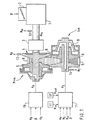
In der Figur 1 ist ein Aufbau eines Umschlingungsgetriebes
im Schnitt dargestellt. Der Verbrennungsmotor 1 kann durch
die Drosselklappe 2 in seinem abgegebenen Motormoment Mm
beeinflußt werden. Die Drosselklappe 2 ist z.B. mechanisch
oder elektrisch mit dem Fahrpedal (nicht dargestellt)
gekoppelt. Der Verbrennungsmotor 1 ist meist mittels einer
Kupplung und/oder einem Wandler 3 an die Antriebs- (Primär-)
Seite des CVT-Getriebes 4 angekoppelt. Die Abtriebs-(Sekundär-)
Seite des CVT-Getriebes 4 ist über ein
nachgeschaltetes Getriebe (nicht dargestellt) mit den Rädern
des Fahrzeugs verbunden. Das CVT-Getriebe besitzt auf der
Primär- und Sekundärseite je eine axial verschiebbare Kegelscheibe
5 und 6. Zur Verstellung der Übersetzung wird in den
Ölkammern 7 und 8 ein entsprechender Primärdruck Pp bzw.
Sekundärdruck Ps aufgebaut. Durch eine geeignete Wahl der
Stellgrößen Primärdruck Pp und Sekundärdruck Ps muß gewährleistet
werden, daß
Der obengenannte Punkte 1 wird durch eine elektrohydraulische
Übersetzungs- oder Primärdrehzahlregelung 10 realisiert.
Für den Punkt 2 wird eine Bandspannungsregelung 11
eingesetzt.The
In dem häufig eingesetzten und in der Figur 1 gezeichneten
Master-Slave-Prinzip dient der Sekundärdruck Ps zur Einstellung
der Bandspannung und der Primärdruck Pp zur Einstellung
der Übersetzungs- bzw. Primärdrehzahl. Zur
Bandspannungsregelung wird dem Block 11 neben der
Primärdrehzahl Np und der Sekundärdrehzahl NS die
Motordrehlzahl Nm (Drehzahlsensor 12) und die
Ausgangssignale Nin und Nout der noch zu beschreibenden
Sensoreinheiten S1 und S2 zugeführt. Abhängig von diesen
Signalen wird ein einzustellender Sekundärdruck PS
ermittelt. Dies wird im folgenden genauer anhand der Figur 3
und 4 beschrieben werden.In the frequently used master-slave principle shown in FIG. 1, the secondary pressure P s is used to adjust the belt tension and the primary pressure P p is used to adjust the transmission or primary speed. In addition to the primary speed N p and the secondary speed N S, the engine speed N m (speed sensor 12) and the output signals N in and N out of the sensor units S1 and S2 to be described are supplied to the
Bei dem alternativ möglichen Partner-Prinzip beeinflußt die Bandspannungsregelung sowohl den Primär- als auch den Sekundärdruck.In the alternative possible partner principle, the Belt tension control of both the primary and the Secondary pressure.
Wie schon erwähnt wird in solchen CVT-Getrieben das Moment
mit einem Umschlingungselement 9 zwischen den zwei in der
Figur 1 gezeigten Pulleysätzen übertragen. Die Änderung der
Getriebeübersetzung wird durch ein Verstellen der aktiven
Radien der Pulleys erreicht. Die Pulleysätze sind aus je
zwei Kegelstümpfen beziehungsweise Kegelscheiben aufgebaut,
die gegeneinander verschoben werden können. Dies ist als
Prinzipbild in der Figur 2 dargestellt. Hier ist ein
Schnittbild senkrecht zu den Achsen der Kegelstümpfen
beziehungsweise Kegelscheiben gezeigt, wobei mit dem Pfeil 2
die Drehrichtung im Normal-Vorwärtsbetrieb des Fahrzeugs
angezeigt ist. Das Umschlingungselement 9 ist dabei in zwei
Extremübersetzungseinstellungen umin und umax mit Strichen
und Punkten eingezeichnet. Die motorseitige Primärseite ist
mit Prim. und die den Fahrzeugrädern zugewandte Seite mit
Sek. bezeichnet.As already mentioned, in such CVT transmissions the torque is transmitted with a
Durch das Verschieben der Kegelscheiben gegeneinander ändern
sich die aktiven Radien für das Umschlingungselement, das in
diesem Beispiel ein Schubgliederband 9 sein soll. Der
Radius, an dem das Umschlingungselement 9 auf der
Primärseite Prim. wirkt, das heißt an dem die Kraft
übertragen wird, wird mit rp bezeichnet, der auf der
Sekundärseite Sek. mit rs. Diese Radien können als
theoretische Größe ermittelt werden, selbst wenn das
Umschlingungsband 9 nicht ideal auf den so ermittelten
Kreissegmenten abläuft. Die Länge Lr des Umschlingungsbandes
9 kann als konstant angenommen werden. Die Annahme, daß sich
die Bahn des Umschlingungselements 9 aus zwei Kreissegmenten
und zwei Geradenstücken zusammensetzt (siehe Figur 2), ist
in weiten Betriebsbereichen richtig und kann ohne großen
Fehler immer angenommen werden.By moving the conical disks against each other, the active radii for the wrapping element, which in this example is supposed to be a
Wie in der Figur 2 zu sehen ist, haben die Achsen der
Pulleys einen festen Abstand a. Für die erfindungsgemäße
Idee werden in der Mitte zwischen den beiden Pulleys, also
bei a/2, je eine Sensoreinheit S1 und S2 angeordnet. Diese
Sensoren sind so beschaffen, daß sie einzelne Segmente 502
beziehungsweise Marken auf dem Umschlingungselement zählen
können. Die Segmente beziehungsweise Marken sind mit exakt
konstanten Abständen auf dem Umschlingungselement 9
angebracht. Hierauf wird noch detaillierter anhand der Figur
5 eingegangen.As can be seen in Figure 2, the axes of the
Pulleys a fixed distance a. For the invention
Idea will be in the middle between the two pulleys, so
at a / 2, one sensor unit S1 and S2 each. This
Sensors are designed to separate
Die erfindungsgemäße Idee basiert darauf, daß die Länge Lp
des Umschlingungselements 9 zwischen den Sensoren S1 und S2
auf der Primärseite Prim. (und natürlich auch auf der
Sekundärseite Sek.) ein direktes Maß für die geometrische
Übersetzung ugeo (=rs/rp) ist. Dies soll anhand der
folgenden Betrachtung der geometrischen Verhältnisse des
Umschlingungsgetriebes verdeutlich werden.The idea according to the invention is based on the fact that the length L p of the
Das geometrische Übersetzungsverhältnis ugeo ist definiert
als:

Die Länge Lp des Bandes 9 zwischen den Meßpunkten der
Sensoreinheiten S1 und S2 ergibt sich zu:
Damit ergibt sich für die die Umschlingungslänge Lup des
Primärpulleys und für den der Weg Lap zwischen dem
Berührungspunkt am Primärpulley und den Sensoreinheiten S1
und S2:

Damit ist die Länge Lp des Schubgliederbandes zwischen den
Sensoreinheiten S1 und S2 eine Funktion, die nur von dem
Primärradius rp abhängt:
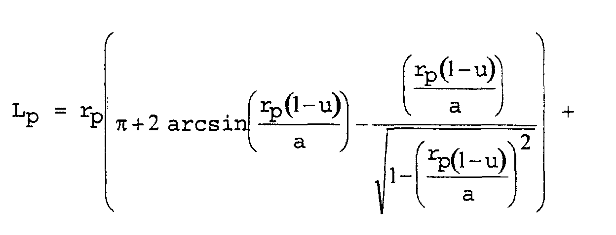


Für ein bekanntes Getriebe ist rp eine Funktion der
geometrischen Übersetzung ugeo=u, in die nur die
Getriebeparameter Lr (Länge des Bandes) und a (Abstand der
Achsen der Pulleys) eingehen.

Die Gleichung 8 in die Gleichung 7c eingesetzt führt zu
einer Gleichung zur Bestimmung von Lp, die ausschließlich
von der geometrischen Übersetzung ugeo=u und fest
eingestellten Getriebeparametern abhängt. Wird diese
Gleichung in einer Kennlinie abgelegt, so kann
beispielsweise aus der Länge Lp des auf der Primärseite
gespeicherten Umschlingungselements 9 die geometrische
Übersetzung ugeo bestimmt werden.
Arbeitet das System ohne einen merklichen Schlupf zwischen
Band und Pulleys, so muß die geometrische Übersetzung ugeo
gleich der Drehzahlübersetzung uN=Np/Ns sein. Np und Ns sind
dabei die Drehzahlen der Primär- und Sekundärseite (Sensoren
13, 14). Sind diese beiden Übersetzungen nicht gleich, so
arbeitet das System mit einem bestimmten Bandschlupf.If the system works without any noticeable slippage between the belt and pulleys, the geometric translation u geo must be equal to the speed translation u N = Np / Ns. N p and N s are the speeds of the primary and secondary sides (
Im folgenden soll anhand der Figuren 3 und 4 ein konkretes Ausführungsbeispiel beschrieben werden.In the following, a concrete one will be shown with reference to FIGS Embodiment will be described.
Wie in der Figur 4 zu sehen ist, wird im Schlupfreglerblock
11 zunächst im Block 111 die Drehzahlübersetzung uN = Np/Ns
ermittelt. Wesentlich für die Erfindung ist der Block 112,
dem die Ausgangssignale Nin und Nout der Sensoren S1 und S2
zugeführt werden. Wie erwähnt sind diese Sensoren S1 und S2
so beschaffen, daß sie einzelne Segmente 502 beziehungsweise
Marken auf dem Umschlingungselement zählen können. Die
Segmente beziehungsweise Marken sind mit exakt konstanten
Abständen auf dem Umschlingungselement 9 angebracht. Weist
das Getriebe die in der Figur 2 mit dem Pfeil 2
gekennzeichnete Drehrichtung auf, so zählt die Sensoreinheit
S1 die auf der Primärseite einlaufenden Bandsegmente Nin
beziehungsweise Bandmarkierungen und die Sensoreinheit S2
die von der Primärseite weglaufenden Bandsegmente Nout
beziehungsweise Bandmarkierungen.As can be seen in FIG. 4, the speed ratio u N = Np / Ns is first determined in the
Gemäß der Figur 3, die die Funktion des Blocks 112 (Fig.4)
zeigt, wird nach dem Startschritt 301 im Schritt 302 die
aktuelle Drehzahlübersetzung uN eingelesen.According to FIG. 3, which shows the function of block 112 (FIG. 4), the current speed ratio u N is read in after
In den jeweiligen Endlagen (bei der kleinsten und der
größten Getriebeübersetzung) ist die Zahl der Segmente
beziehungsweise Marken, die sich auf der Primärseite und auf
der Sekundärseite befinden, bekannt. Bei Vorliegen dieser
Betriebsbedingungen (bei der kleinsten und der größten
Getriebeübersetzung umin, umax) kann die Messung einfach
gestartet werden. Im Schritt 303 wird aus diesem Grund
abgefragt, ob eine solche Betriebsbedingung mit umin oder
umax vorliegt. Der Betriebszustand maximaler oder minimaler
Übersetzung kann aber auch durch andere Paramter ermittelt
werden, beispielsweise durch Einlesen des Primär- und/oder
Sekundärdrucks.In the respective end positions (with the smallest and the largest gear ratio), the number of segments or brands that are located on the primary side and on the secondary side is known. If these operating conditions exist (with the smallest and the largest gear ratio u min , u max ), the measurement can be started easily. For this reason, it is queried in
Zumindest am Anfang der Messung muß einmal ein solcher
Betriebszustand erreicht werden. Wird im Schritt 303 ein
Betriebszustand maximaler oder minimaler Übersetzung
festegestellt, so wird als Startwert Lstart für die Länge Lp
des Bandes 9 auf der Primärseite zwischen den Meßpunkten der
Sensoreinheiten S1 und S2 der Startwert Lmin beziehungsweise
Lmax gesetzt.Such an operating state must be reached at least at the beginning of the measurement. If an operating state of maximum or minimum translation is determined in
Im Schritt 305 werden dann die Ausgangssignale Nin und Nout
der Sensoren S1 und S2 eingelesen, die die auf der
Primärseite einlaufenden und auslaufenden Segmente angeben.
Im Schritt 306 wird die aktuelle Länge Lp des Bandes 9 auf
der Primärseite zwischen den Meßpunkten der Sensoreinheiten
S1 und S2 derart ermittelt, daß zu dem Startwert Lstart die
Anzahl der einlaufenden Segmente addiert und die Anzahl der
auslaufenden Segmente subtrahiert werden.In
Im Schritt 307 wird aus dem Wert Lp aus der oben
hergeleiteten Kennlinie (Gleichung 7c und 8) die
geometrische Übersetzung ugeo ermittelt.In
Wird nach einem ersten Startdurchlauf im Schritt 303
festgestellt, daß keine extreme Übersetzung umin oder umax
eingestellt ist, so werden im Schritt 308 die
Ausgangssignale Nin und Nout der Sensoren S1 und S2
eingelesen, die die auf der Primärseite einlaufenden und
auslaufenden Segmente angeben. Im Schritt 309 wird die
aktuelle Länge Lp des Bandes 9 auf der Primärseite zwischen
den Meßpunkten der Sensoreinheiten S1 und S2 derart
ermittelt, daß zu dem vorhergehend ermittelten Wert Lp die
Anzahl der einlaufenden Segmente addiert und die Anzahl der
auslaufenden Segmente subtrahiert werden. Mit dem schon
beschriebenen Block 307 wird die geometrische Übersetzung
ermittelt.If it is determined after a first start run in
Aus der im Block 111 und 112 der Figur 4 ermittelten
aktuellen Drehzahlübersetzung uN und aktuellen geometrischen
Übersetzung ugeo wird im Block 113 ein aktueller Wert λB,ist
für den Bandschlupf λB berechnet (beispielsweise durch
Differenzbildung). Dieser Wert λB,ist wird dann im Block 114
mit einem entsprechenden Sollwert λB,soll verglichen,
woraufhin abhängig von diesem Vergleich die Bandspannung
(beispielsweise durch Einstellung des Sekundärdrucks ps beim
eingangs erwähnten Master-Slave-Prinzip) derart eingestellt
wird, daß kein Schlupf vorliegt (Regler R, Block 1142).From the current speed translation u N and the current geometric translation u geo determined in
Der Sollwert λB,soll für den Bandschlupf wird, wie eingangs erwähnt, unter Berücksichtigung des Motormoments und der Motordrehzahl ermittelt.The nominal value λ B, should for the belt slip is, as mentioned at the beginning, determined taking into account the engine torque and the engine speed.
In der Figur 5 werden einige Ausführungsformen der Bandsegmente beziehungsweise der Bandmarkierungen vorgestellt.5 shows some embodiments of the Band segments or the band markings presented.
Ein Schubgliederband besteht bekannterweise aus einer
Vielzahl von Segmenten 502, die durch einen Federstahlring
503 zusammengehalten werden. Die Figur 5a zeigt ein
konventionelles Schubgliederband 9 mit einzelnen Segmenten
502, wobei ein einzelnen Segment 502 (ohne gestrichelte
Ausführungsform) in der Figur 5b zu sehen ist.A thrust link belt is known to consist of one
Variety of
Wie in der Figur 5a gezeigt, kann bei konventionellen
Schubgliederbändern auf das Anbringen von auswertbaren
Marken verzichtet werden, da die Segmente selbst schon durch
die detektierbaren Lücken 501 mittels bekannter geeigneter
magnetischer Sensoren S1 und S2 gezählt werden können.
Darüber hinaus ist insbesondere an die Verwendung von an
sich bekannten Wirbelstrom-Sensoren gedacht.As shown in Figure 5a, conventional
Push link belts for attaching evaluable
Brands are dispensed with, because the segments are already through
the
Eine weitere Möglichkeit für eine noch deutlichere
Detektierung der Segmente 502 ist in der Figur 5c
dargestellt. Hier wurde jedes zweite Segment 502 an der
Band-Außenseite A um einige Millimeter verlängert (siehe
auch gestrichelte Darstellung des Segmentes 502 in der Figur
5b). Eine solche Markierung ist noch einfacher zu
detektieren als die Lücken auf der Innenseite des in der
Figur 5a gezeigten konventionellen Bandes. Bei der in der
Figur 5c dargestellten Ausführungsform müssen die
Sensoreinheiten S1 und S2 selbstverständlich an der
Außenseite des Bandes angeordnet sein.Another way for an even clearer
Detection of
Claims (8)
- Device for the operation of a wrap-around transmission of which the ratio can be adjusted, having a drive side (Prim.) and an output side (Sek.) and having wrap-around means (9) subdivided into individual segments (502) to provide a mechanical operative connection between the drive and output side of which the slip behaviour can be influenced, and influencing means (11) by means of which the slip (λB) of the wrap-around means (9) is influenced, characterized in that at least two sensor units (S1, S2) are provided, which are arranged in the region of the wrap-around means (9) and between the drive side and an output side, in such a way that their signals (Nin, Nout) represent the segment leading past the sensor units (S1, S2), one of the sensor units (S1, S2) being arranged in such a way that its signal (Nin) represents the segments (502) leading towards the drive or output side, and the other of the sensor units (S1, S2) being arranged in such a way that its signal (Nout) represents the segments (502) leading away from the drive or output side, and the signals (Nin, Nout) being supplied to the influencing means (11) in order to influence the slip (λB) of the wrap-around means (9).
- Device according to Claim 1, characterized in that the sensor units (S1, S2) are arranged in such a way that the sensor units register the changes in the relative position between the wrap-around means (9) and the sensor units.
- Device according to Claim 1, characterized in that the drive side (Prim.) and/or the output side (Sek.) has at least one axially displaceable element (5, 6) which has substantially the shape of a conical disk.
- Device according to Claim 1 or 3, characterized in that as the wrap-around means, at least one belt, preferably a thrust-element belt (9) or a belt or a chain is tensioned between pairs of disks, which represent the drive and the output side, it being possible for the slip (λB) between the wrap-around means and the pairs of disks that tension the wrap-around means to be influenced.
- Device according to Claim 1, characterized in that the influencing means (11) are configured in such a way that a geometric transmission ratio (ugeo) depending on the difference (Nin-Nout) between the two sensor signals is formed.
- Device according to Claim 5, characterized in that first and second rotational speed registering means (13, 14) are provided to register the rotational speed of the drive and/or output side, and the output signals (Np, Ns) from these rotational speed registering means are supplied to the influencing means (11), and the influencing means (11) are configured in such a way that, depending on the output signals (Np, Ns) from these rotational speed registering means, a rotational speed transmission ratio (uN) is determined and, by means of a comparison between the geometric transmission ratio (ugeo) and the rotational speed transmission ratio (uN), the current slip (λB,act) of the wrap-around means (9) is inferred.
- Device according to Claim 1 or 6, characterized in that the influencing means (11) are configured in such a way that the slip (λB) is regulated to a predefinable value (λsp), the current slip (λB,act) being compared with a predefinable set point (λB,sp) in order to regulate the slip.
- A method for the operation of a wrap-around transmission of which the ratio can be adjusted, having a drive side (Prim.) and an output side (Sek.) and having wrap-around means (9) to produce a mechanical operative connection between the drive side and output side whose slip behaviour can be influenced, the slip (λB) of the wrap-around means (9) being influenced, characterized in thatthe parts (Nin) of the wrap-around means (9) leading towards the drive side (Prim.) or output side (Sek.), and the parts (Nout) of the wrap-around means (9) leading away from the drive side (Prim.) or output side (Sek.) are registered, andthe slip (λB) of the wrap-around means (9) is influenced on the basis of the parts (Nin, Nout) registered.
Applications Claiming Priority (3)
| Application Number | Priority Date | Filing Date | Title |
|---|---|---|---|
| DE19638277 | 1996-09-19 | ||
| DE19638277A DE19638277A1 (en) | 1996-09-19 | 1996-09-19 | Device and method for operating a belt transmission |
| PCT/DE1997/001104 WO1998012457A1 (en) | 1996-09-19 | 1997-05-27 | Method and device for the operation of a flexible drive mechanism |
Publications (2)
| Publication Number | Publication Date |
|---|---|
| EP0858564A1 EP0858564A1 (en) | 1998-08-19 |
| EP0858564B1 true EP0858564B1 (en) | 2002-08-07 |
Family
ID=7806157
Family Applications (1)
| Application Number | Title | Priority Date | Filing Date |
|---|---|---|---|
| EP97924926A Expired - Lifetime EP0858564B1 (en) | 1996-09-19 | 1997-05-27 | Method and device for the operation of a flexible drive mechanism |
Country Status (6)
| Country | Link |
|---|---|
| US (1) | US6146294A (en) |
| EP (1) | EP0858564B1 (en) |
| JP (1) | JP4112013B2 (en) |
| KR (1) | KR100498796B1 (en) |
| DE (2) | DE19638277A1 (en) |
| WO (1) | WO1998012457A1 (en) |
Families Citing this family (21)
| Publication number | Priority date | Publication date | Assignee | Title |
|---|---|---|---|---|
| JP3523114B2 (en) * | 1999-02-25 | 2004-04-26 | 日産自動車株式会社 | Method of manufacturing pulley for continuously variable transmission |
| DE19937472C1 (en) * | 1999-08-07 | 2000-11-30 | Zahnradfabrik Friedrichshafen | Variator slip regulation method for automobile continuously variable transmission has slip counter of evalaution module indexed simultaneous with incrementation of slip counter field for weighting slip duration and intensity |
| JP3571607B2 (en) * | 2000-03-27 | 2004-09-29 | 本田技研工業株式会社 | Belt type continuously variable transmission |
| JP3750488B2 (en) * | 2000-05-23 | 2006-03-01 | トヨタ自動車株式会社 | Control device for continuously variable transmission for vehicle |
| NL1015489C2 (en) * | 2000-06-21 | 2001-12-28 | Doornes Transmissie Bv | Drive belt and cross element for a drive belt. |
| DE10059450A1 (en) * | 2000-11-30 | 2002-06-13 | Zf Batavia Llc | Variator slip detection method for continuously variable transmission uses detection and analysis of vibration noise |
| IL141094A0 (en) | 2001-01-25 | 2002-02-10 | Ran Siman Tov | Continuous variable transmission |
| DE10130231A1 (en) * | 2001-06-22 | 2003-01-16 | Bosch Gmbh Robert | Method and system for slip detection of a belt part of a belt transmission |
| DE10163842B4 (en) * | 2001-12-22 | 2020-06-18 | Robert Bosch Gmbh | Device and method for determining the transmission ratio of a continuously variable belt transmission and control circuit |
| US6974009B2 (en) * | 2002-02-04 | 2005-12-13 | Toyota Jidosha Kabushiki Kaisha | Control apparatus for power train including continuously variable transmission |
| DE10357169B4 (en) * | 2002-12-10 | 2015-01-29 | Schaeffler Technologies Gmbh & Co. Kg | Device for detecting the speed of the belt of a belt pulley belt drive |
| EP1526309B1 (en) | 2003-10-22 | 2007-04-25 | Robert Bosch Gmbh | Continuously variable transmission |
| DE102005041065A1 (en) | 2005-02-16 | 2006-08-24 | Patent-Treuhand-Gesellschaft für elektrische Glühlampen mbH | lighting device |
| CN103172840B (en) | 2005-04-22 | 2016-03-02 | 三菱化学株式会社 | From polyester and the manufacture method thereof of biomass resource |
| EP1777441A1 (en) * | 2005-10-24 | 2007-04-25 | Getrag Ford Transmissions GmbH | Continuously variable transmission and control process |
| JP5030492B2 (en) * | 2006-07-12 | 2012-09-19 | ヤマハ発動機株式会社 | Belt type continuously variable transmission and saddle type vehicle |
| DE102006037936B3 (en) * | 2006-08-11 | 2008-01-31 | Technische Universität Bergakademie Freiberg | Traction drive for cam shaft at internal-combustion engine, has detection device with form-fit traction unit arranged parallel to force-fit traction unit and disk arranged on form-fit traction unit relative to bevel washer |
| DE102006044040B4 (en) * | 2006-09-14 | 2013-02-28 | Technische Universität Bergakademie Freiberg | Traction mechanism with non-positive traction means and adjustable preload |
| WO2008050687A1 (en) * | 2006-10-23 | 2008-05-02 | Jtekt Corporation | Control device for stepless transmission, flow rate control method, and flow rate control device |
| NL2002373C2 (en) * | 2008-12-24 | 2010-06-28 | Bosch Gmbh Robert | Method for controlling a friction transmission such as a friction clutch or a continuously variable transmission. |
| DE102021122242A1 (en) | 2021-08-27 | 2023-03-02 | Arntz Beteiligungs Gmbh & Co. Kg | Device and method for determining at least one measured variable in a belt-operated variator transmission, control system, computer program and belt |
Family Cites Families (17)
| Publication number | Priority date | Publication date | Assignee | Title |
|---|---|---|---|---|
| DE1574298A1 (en) * | 1966-10-26 | 1971-05-13 | Agfa Gevaert Ag | Device for adjusting the position of an endless belt |
| US4061222A (en) * | 1975-07-09 | 1977-12-06 | Eastman Kodak Company | Web tracking apparatus |
| DE2755424C2 (en) * | 1977-12-13 | 1986-03-20 | Daimler-Benz Ag, 7000 Stuttgart | Device for measuring the slip |
| NL8103554A (en) * | 1981-07-28 | 1983-02-16 | Varicar Bv | Infinitely variable cone pulley belt drive - controls axial cone pressures as function of torque allowing controlled limited slip |
| US4557372A (en) * | 1984-08-13 | 1985-12-10 | The Mead Corporation | Belt system with alignment apparatus |
| JPS62292950A (en) * | 1986-06-12 | 1987-12-19 | Daihatsu Motor Co Ltd | Belt slip detecting method for v-belt type continuously variable transmission |
| US4959040A (en) * | 1989-04-21 | 1990-09-25 | Rastergraphics Inc. | Method and apparatus for precisely positioning and stabilizing a continuous belt or web or the like |
| NL9000589A (en) * | 1990-03-15 | 1991-10-01 | Doornes Transmissie Bv | CONTINUOUSLY VARIABLE TRANSMISSION. |
| NL9000860A (en) * | 1990-04-12 | 1991-11-01 | Doornes Transmissie Bv | ELECTRONICALLY CONTROLLED CONTINUOUSLY VARIABLE TRANSMISSION. |
| US5173084A (en) * | 1991-12-23 | 1992-12-22 | Ford Motor Company | Self-clamping assist for "V" belt continuously variable transmissions |
| US5213548A (en) * | 1992-03-02 | 1993-05-25 | Colbert Ralph G | Gear shifting system for derailleur equipped bicycle |
| US5328412A (en) * | 1992-10-21 | 1994-07-12 | Borg-Warner Automotive, Inc. | Apparatus and method for generating a variable pulley sheave profile |
| US5383014A (en) * | 1993-05-20 | 1995-01-17 | Xerox Corporation | Photoreceptor belt motion sensor using linear position sensors |
| JP2851533B2 (en) * | 1994-03-23 | 1999-01-27 | 三菱重工業株式会社 | Single facer |
| DE4411628A1 (en) | 1994-04-02 | 1995-10-05 | Bosch Gmbh Robert | Slip controller for continuously variable transmission |
| DE4440278C1 (en) * | 1994-11-11 | 1995-11-30 | Telefunken Microelectron | Device for determination of belt running speed in stepless transmission in motor vehicle |
| US5662538A (en) * | 1996-03-11 | 1997-09-02 | Wang; Fue-Jye | Device for adjusting pitch diameter of sheave of variable speed mechanism |
-
1996
- 1996-09-19 DE DE19638277A patent/DE19638277A1/en not_active Withdrawn
-
1997
- 1997-05-27 JP JP51412498A patent/JP4112013B2/en not_active Expired - Lifetime
- 1997-05-27 WO PCT/DE1997/001104 patent/WO1998012457A1/en active IP Right Grant
- 1997-05-27 EP EP97924926A patent/EP0858564B1/en not_active Expired - Lifetime
- 1997-05-27 DE DE59707914T patent/DE59707914D1/en not_active Expired - Lifetime
- 1997-05-27 US US09/077,071 patent/US6146294A/en not_active Expired - Fee Related
- 1997-05-27 KR KR10-1998-0703711A patent/KR100498796B1/en not_active IP Right Cessation
Also Published As
| Publication number | Publication date |
|---|---|
| JP4112013B2 (en) | 2008-07-02 |
| DE19638277A1 (en) | 1998-03-26 |
| DE59707914D1 (en) | 2002-09-12 |
| US6146294A (en) | 2000-11-14 |
| KR19990067682A (en) | 1999-08-25 |
| JP2000500850A (en) | 2000-01-25 |
| WO1998012457A1 (en) | 1998-03-26 |
| KR100498796B1 (en) | 2005-09-14 |
| EP0858564A1 (en) | 1998-08-19 |
Similar Documents
| Publication | Publication Date | Title |
|---|---|---|
| EP0858564B1 (en) | Method and device for the operation of a flexible drive mechanism | |
| DE10020643C2 (en) | Arrangement for the torque-free shifting of a transmission | |
| EP0970319B1 (en) | Device and method for reducing slip in the control system of a cvt in a motor vehicle | |
| DE19632109B4 (en) | A slip control device for a vehicle form-locking clutch, with the slip control is terminated during the vehicle deceleration when the slip amount of the clutch is greater than a threshold value | |
| DE4427359C2 (en) | Method and device for controlling the engagement state of a lock-up clutch | |
| EP1499900B1 (en) | Method for determining the rotational speed of a part | |
| DE3509017A1 (en) | STEPLESS POWER TRANSMISSION FOR MOTOR VEHICLES | |
| WO1999016635A1 (en) | Device and method for adjusting the transmission ratio of a cvt | |
| DE3902692C2 (en) | Control and method for continuously variable gear arrangement | |
| WO1998042531A1 (en) | Device and method for controlling a cvt in a motor vehicle | |
| WO2000075536A1 (en) | Method for operating an actuation device of an automated transmission | |
| DE102005024091A1 (en) | Method and device for rewinding a tape | |
| DE60315893T2 (en) | METHOD FOR ACTUATING A STEP-FREE GEARBOX | |
| EP0352277B1 (en) | Device for controlling an automatic motor vehicle clutch | |
| DE19505561C2 (en) | Method and device for slip control of friction elements or gears | |
| DE60119250T2 (en) | Control device for a continuously variable transmission | |
| DE60310838T2 (en) | Stepless transmission control system in the event of failure of a hydraulic pressure sensor | |
| DE112013000322T5 (en) | Control device for vehicle power transmission mechanism | |
| CH691275A5 (en) | Method and apparatus for transition detection in a motor vehicle. | |
| EP1194686B1 (en) | Method and device for controlling the drive unit of a vehicle | |
| EP0929409B1 (en) | Device and method for adjusting the ratio of transmission in a cvt | |
| DE102004009694B4 (en) | Shift control system in a belt-type continuously variable transmission | |
| DE10130231A1 (en) | Method and system for slip detection of a belt part of a belt transmission | |
| DE3809118A1 (en) | Device for controlling an automatic motor vehicle clutch | |
| EP1314913B1 (en) | Method for controlling a continuously variable transmission and transmission for a vehicle |
Legal Events
| Date | Code | Title | Description |
|---|---|---|---|
| PUAI | Public reference made under article 153(3) epc to a published international application that has entered the european phase |
Free format text: ORIGINAL CODE: 0009012 |
|
| AK | Designated contracting states |
Kind code of ref document: A1 Designated state(s): DE FR IT NL |
|
| 17P | Request for examination filed |
Effective date: 19980928 |
|
| 17Q | First examination report despatched |
Effective date: 20001110 |
|
| GRAG | Despatch of communication of intention to grant |
Free format text: ORIGINAL CODE: EPIDOS AGRA |
|
| GRAG | Despatch of communication of intention to grant |
Free format text: ORIGINAL CODE: EPIDOS AGRA |
|
| GRAH | Despatch of communication of intention to grant a patent |
Free format text: ORIGINAL CODE: EPIDOS IGRA |
|
| GRAH | Despatch of communication of intention to grant a patent |
Free format text: ORIGINAL CODE: EPIDOS IGRA |
|
| GRAA | (expected) grant |
Free format text: ORIGINAL CODE: 0009210 |
|
| AK | Designated contracting states |
Kind code of ref document: B1 Designated state(s): DE FR IT NL |
|
| REF | Corresponds to: |
Ref document number: 59707914 Country of ref document: DE Date of ref document: 20020912 |
|
| ET | Fr: translation filed | ||
| PGFP | Annual fee paid to national office [announced via postgrant information from national office to epo] |
Ref country code: NL Payment date: 20030527 Year of fee payment: 7 |
|
| PLBE | No opposition filed within time limit |
Free format text: ORIGINAL CODE: 0009261 |
|
| STAA | Information on the status of an ep patent application or granted ep patent |
Free format text: STATUS: NO OPPOSITION FILED WITHIN TIME LIMIT |
|
| 26N | No opposition filed |
Effective date: 20030508 |
|
| PG25 | Lapsed in a contracting state [announced via postgrant information from national office to epo] |
Ref country code: NL Free format text: LAPSE BECAUSE OF NON-PAYMENT OF DUE FEES Effective date: 20041201 |
|
| NLV4 | Nl: lapsed or anulled due to non-payment of the annual fee |
Effective date: 20041201 |
|
| PGFP | Annual fee paid to national office [announced via postgrant information from national office to epo] |
Ref country code: IT Payment date: 20080524 Year of fee payment: 12 |
|
| PG25 | Lapsed in a contracting state [announced via postgrant information from national office to epo] |
Ref country code: IT Free format text: LAPSE BECAUSE OF NON-PAYMENT OF DUE FEES Effective date: 20090527 |
|
| PGFP | Annual fee paid to national office [announced via postgrant information from national office to epo] |
Ref country code: FR Payment date: 20140516 Year of fee payment: 18 |
|
| PGFP | Annual fee paid to national office [announced via postgrant information from national office to epo] |
Ref country code: DE Payment date: 20150723 Year of fee payment: 19 |
|
| REG | Reference to a national code |
Ref country code: FR Ref legal event code: ST Effective date: 20160129 |
|
| PG25 | Lapsed in a contracting state [announced via postgrant information from national office to epo] |
Ref country code: FR Free format text: LAPSE BECAUSE OF NON-PAYMENT OF DUE FEES Effective date: 20150601 |
|
| REG | Reference to a national code |
Ref country code: DE Ref legal event code: R119 Ref document number: 59707914 Country of ref document: DE |
|
| PG25 | Lapsed in a contracting state [announced via postgrant information from national office to epo] |
Ref country code: DE Free format text: LAPSE BECAUSE OF NON-PAYMENT OF DUE FEES Effective date: 20161201 |