EP1777441A1 - Continuously variable transmission and control process - Google Patents
Continuously variable transmission and control process Download PDFInfo
- Publication number
- EP1777441A1 EP1777441A1 EP05109897A EP05109897A EP1777441A1 EP 1777441 A1 EP1777441 A1 EP 1777441A1 EP 05109897 A EP05109897 A EP 05109897A EP 05109897 A EP05109897 A EP 05109897A EP 1777441 A1 EP1777441 A1 EP 1777441A1
- Authority
- EP
- European Patent Office
- Prior art keywords
- transmission
- gear
- transmission member
- friction ring
- input gear
- Prior art date
- Legal status (The legal status is an assumption and is not a legal conclusion. Google has not performed a legal analysis and makes no representation as to the accuracy of the status listed.)
- Withdrawn
Links
Images


Classifications
-
- F—MECHANICAL ENGINEERING; LIGHTING; HEATING; WEAPONS; BLASTING
- F16—ENGINEERING ELEMENTS AND UNITS; GENERAL MEASURES FOR PRODUCING AND MAINTAINING EFFECTIVE FUNCTIONING OF MACHINES OR INSTALLATIONS; THERMAL INSULATION IN GENERAL
- F16H—GEARING
- F16H61/00—Control functions within control units of change-speed- or reversing-gearings for conveying rotary motion ; Control of exclusively fluid gearing, friction gearing, gearings with endless flexible members or other particular types of gearing
- F16H61/66—Control functions within control units of change-speed- or reversing-gearings for conveying rotary motion ; Control of exclusively fluid gearing, friction gearing, gearings with endless flexible members or other particular types of gearing specially adapted for continuously variable gearings
- F16H61/664—Friction gearings
- F16H61/6649—Friction gearings characterised by the means for controlling the torque transmitting capability of the gearing
-
- F—MECHANICAL ENGINEERING; LIGHTING; HEATING; WEAPONS; BLASTING
- F16—ENGINEERING ELEMENTS AND UNITS; GENERAL MEASURES FOR PRODUCING AND MAINTAINING EFFECTIVE FUNCTIONING OF MACHINES OR INSTALLATIONS; THERMAL INSULATION IN GENERAL
- F16H—GEARING
- F16H15/00—Gearings for conveying rotary motion with variable gear ratio, or for reversing rotary motion, by friction between rotary members
- F16H15/02—Gearings for conveying rotary motion with variable gear ratio, or for reversing rotary motion, by friction between rotary members without members having orbital motion
- F16H15/04—Gearings providing a continuous range of gear ratios
- F16H15/42—Gearings providing a continuous range of gear ratios in which two members co-operate by means of rings or by means of parts of endless flexible members pressed between the first mentioned members
Definitions
- the invention relates to a continuously variable transmission and a method for controlling the continuously variable transmission.
- a continuously variable transmission comprises an input gear, an output gear and a transmission member.
- the input gear is connected via a clutch to the engine of the motor vehicle, so that the torque can be passed from the engine to the input gear.
- the output gear of the continuously variable transmission is non-rotatably mounted on an output shaft, which is usually connected via a differential with the driven axles of the motor vehicle.
- the transmission member is frictionally engaged with both the input and output gears and allows torque to be transmitted from the input gear to the output gear.
- the ratio of the continuously variable transmission depends on a radius of a point of force application between the input gear and the transmission element and on a radius of a point of application of force between the output gear and the transmission element. By continuously changing these radii, the ratio can be adjusted accordingly.
- An example of a continuously variable transmission is a conical friction ring gear.
- Input wheel and output gear are designed as conical friction wheels. These conical friction wheels are arranged opposite to each other on parallel shafts.
- the transmission member is designed as a friction ring, which engages with both conical friction wheels and engages around one of the conical friction wheels.
- the case may occur that the total slip is approximately equally divided between the inner and outer contact of the friction ring, wherein both the individual slip of the inner contact and the single slip of the Au ⁇ ennapss each move within tolerable limits.
- the total slip is due mainly or in large part to only a single slip, this single slip then goes beyond the critical level, while the total slip, as in the above first case, still assumes no uncritical value.
- the conical friction wheels can be moved axially to each other so as to clamp the interposed friction ring with a larger axial force.
- the axial forces unnecessarily too high, this in turn has disadvantages in terms of the efficiency of the transmission: high clamping forces of the friction ring lead to high transmission losses and unwanted material loads.
- the invention is therefore based on the object to provide a method for controlling a continuously variable transmission, with which the continuously variable transmission can be operated as efficiently and safely.
- the inventive method is characterized in that in addition to the rotational speeds of input and output gear and a rotational speed or rotational speed of the transmission member is determined. If the speeds of input edge, output wheel and transmission element are known, the slip between the input wheel and the transmission element and the slip between the transmission element and the output wheel can be determined.
- a preferred way to influence the individual slips is to regulate the contact force acting between the input gear and transmission element or between the transmission member and output gear. If, for example, a large single slip is determined in a bevel ring gear, the two conical friction wheels and the friction ring between them can be clamped with a larger axial force. In this case, both the individual slip between input gear and friction ring and the single slip between friction ring and output gear is reduced.
- a supply of a traction fluid is regulated to a contact zone between the input gear and the transmission member and / or to a contact zone between the transmission member and the output wheel.
- a supply of a traction fluid is regulated to a contact zone between the input gear and the transmission member and / or to a contact zone between the transmission member and the output wheel.
- the contact zone between the input gear and the transmission element and the contact zone between the transmission element and the output gear can be supplied with the traction fluid independently of one another.
- the capacity and durability of the continuously variable transmission can be significantly improved without the need for an excessive amount of traction fluid.
- traction fluid as a function of transmission parameters, such as speed, slip, torque, contact pressure, temperature, driving situation, etc. targeted to a contact zone between the input gear and transmission element or to guide between transmission element and output gear, may otherwise generally in transmissions are used, in which two components are frictionally engaged and transmitted under slip torque.
- the traction fluid for example a high-traction lubricant, can be pressurized via a pump and then fed via suitable feed paths to the corresponding contact zones.
- the adhesion between two components can be influenced in a targeted manner via a regulated supply of the traction fluid or of a traction-promoting agent.
- the continuously variable transmission comprises an input gear, an output gear and a transmission member which frictionally engages both the input gear and the output gear, wherein a ratio adjustment by a stepless change in a radius of a point of force application between the input gear and transmission element and / or by a infinitely variable change of a radius of a force application point between the output gear and the transmission member takes place, and wherein a rotational speed or a rotational speed of the transmission member can be detected.
- Due to the detectability of the speed or the rotational speed of the transmission member can be, as shown above the example of a conical ring gear, with knowledge of the speeds of the input gear and the output gear, determine the individual slips between the input gear and transmission element or between the transmission element and output gear, so that the above-presented method can be applied.
- the continuously variable transmission may be a belt transmission or a Wälzgetriebe.
- the transmission member may be a belt, a belt, a chain or the like.
- the input gear and the output gear can be formed by a pair of disks.
- the band-shaped transmission member is clamped frictionally between the two disc pairs. By varying the rolling radii on the discs, the transmission ratio can be infinitely adjusted.
- the continuously variable transmission can be a Wälzgetriebe.
- a preferred example of a Wälzgetriebe is the cone ring gear, as described above.
- input gear and output gear are designed as conical friction wheels, the are arranged opposite to each other on parallel shafts.
- the transmission member is designed as a friction ring, wherein the friction ring of one of the conical friction wheels surrounds and can be moved in the axial direction of the waves.
- the friction ring may include the input gear or the output gear.
- a sensor for detecting the rotational speed of the friction ring is attached to an adjusting mechanism for the friction ring.
- the adjustment mechanism serves to move the friction ring in the axial direction of the conical friction wheels so as to adjust the transmission ratio.
- the sensor By attaching to the adjusting mechanism, the sensor relative to the friction ring a fixed position and performs the same axial adjustments as the friction ring. Even if the friction ring is tilted out of a plane perpendicular to the waves of the conical friction wheels, thereby initiating axial movement, an appropriate attachment of the sensor to the adjustment mechanism provides the preferred stationary position with respect to the friction ring.
- the friction ring has at least one signal generator, which passes by the sensor when the friction ring rotates.
- the friction ring on a plurality of signal transmitters.
- the sensor detects a signal from a signal generator and can close on the basis of the number of signals per unit time and the number of signal generator on the speed of the friction ring.
- the senor may be an inductive probe.
- This probe detects a magnetic field change, which is generated by the passage of, for example, a ferromagnetic body and induces an electrical voltage.
- the ferromagnetic body is the signal generator. But also elevations, depressions, etc. on the friction ring can act as a signal generator.
- the senor designed as an optical Drehhoffetzsacrificing, a light emitting diode and a phototransistor include.
- the light emitted by the LED illuminates the phototransistor when the light beam of the LED is not interrupted. If the friction ring has a disk with slots or the like, through which the light beam can pass, the light beam will become short when the disk is rotated Time interrupted. This results in a large number of light pulses whose number is a measure of the rotational speed of the friction ring.
- the signal generator may be formed as a web which extends in the axial direction of the friction ring.
- the sensor is preferably aligned with a detection surface radially to the friction ring, wherein the web extending in the axial direction passes by the detection surface of the sensor.
- the signal generator may be formed as a pocket, which is formed in an axial side wall of the friction ring.
- the sensor is aligned with its detection surface axially to the friction ring, so that the pocket formed in the axial side wall of the friction ring can pass flat on the detection surface of the sensor.
- a force in the axial direction of the conical friction wheels is adjustable, with which the friction ring is clamped between the conical friction wheels. This makes it possible to vary depending on the load and situation, the contact pressure between conical friction wheels and friction ring. Thus, the axial force can be increased when the cone ring gear is operated in an operating condition in which one or both individual slips exceed the respective critical level.
- the conical friction wheels are mutually displaceable in the axial direction. This opens up the possibility of controlling the force between the conical friction wheels in the axial direction, for example via an actuator, whereby the contact forces between conical friction wheels and friction ring can be influenced in a targeted manner.
- a supply of a traction fluid to the contact zone of the input gear and the transmission member and / or to the contact zone between the transmission member and the output wheel can be controlled. If, for example, it is found that the slip between input wheel and transmission element is too large, the contact zone between the input wheel and the transmission element can be selectively supplied with traction fluid become. This can be done for example by a pump through which the traction fluid is injected into the contact zone with pressure.
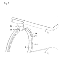
- FIG. 1 shows a continuously variable transmission in the form of a conical-ring transmission 1.
- the conical-ring transmission 1 has a first conical friction wheel 2 and a second conical friction wheel 3.
- the conical friction wheels 2, 3 are arranged opposite to each other, wherein the axes of rotation are parallel and have a certain distance.
- Figure 1 shows a clutch 6 of a motor vehicle not shown here, which is rotatably connected via a shaft 7 with the first bevel friction wheel 2. In a closed state, the clutch 6 transmits a torque via the shaft 7 to the first conical friction wheel 2.
- a friction ring 8 is provided which frictionally engages with both conical friction wheels 2, 3 is engaged and the first Kegelreibrad 2 engages.
- the friction ring 8 can be axially displaced parallel to the axes of rotation 4, 5 of the conical friction wheels 2, 3 via an adjusting mechanism, which is not shown here. By axial displacement or adjustment of the friction ring 8, the transmission ratio of the conical-ring gear 1 can be adjusted.
- the transmitted to the second bevel gear 3 torque is transmitted via a pair of gears, consisting of a gear 9 and meshing with this gear 9 Ring gear 10, passed to an output unit 11, consisting of differential 11 a and 11 b axes, 11 c.
- the differential 11a distributes the torque to the axles 11b, 11c.
- the first bevel friction wheel 2 may be referred to as the input wheel
- the second conical friction wheel 3 as the output wheel in the conical-ring transmission illustrated in FIG.
- the conical friction wheels 2, 3 can be moved relative to each other.
- an actuator (not shown here) with which the conical friction wheels 2, 3 press in the axial direction against the friction ring 8.
- the friction ring 8 has an inner ring surface 12 and an outer ring surface 13.
- the inner ring surface 12 can be assigned a mean inner diameter 14 of the friction ring 8. Accordingly, the ring outer surface 13, a mean outer diameter 15 of the friction ring 8 are assigned.
- the ring inner surface 12 of the friction ring 8 interacts with the first conical friction wheel or input wheel 2.
- the ring outer surface 13 of the friction ring 8 interacts with the second conical friction wheel or output wheel 3.
- the ring inner surface 12 comes into contact with a circumferential segment 16 of the input gear 2, which is shown in dashed lines and defines a mean diameter 17. Since the input gear 2 cooperates with the friction ring 8 at this diameter 17, the diameter 17 can also be referred to as an effective diameter of the input gear 2.
- the output gear 3 a likewise shown in phantom circumference segment 18 on which the friction ring 8 rests with its outer ring surface 13.
- the circumferential segment 18 has an (effective) diameter 19.
- a torque from the input gear 2 is transmitted to the friction ring 8 frictionally.
- the amount of traction fluid in the contact zone can be varied.
- this contact zone 21 can, if necessary, regardless of the amount of traction fluid for contact zone 20, be supplied as needed with traction fluid.
- Figure 2 shows another cone ring gear, which is also designated 1. Identical or similar components to components in the embodiment of Figure 1 are provided with the same reference numerals.
- the friction ring 8 comprises a plurality of webs 22 which extend in the axial direction and have a free end 23. These webs 22, when the friction ring rotates about its axis of rotation, pass by a sensor 24 stationarily arranged for the friction ring, a detection surface 25 of the sensor pointing radially to the interior of the friction ring 8. When passing, the webs generate pulses or triggering, by means of which the rotational speed of the friction ring 8 can be determined. Via a line 26, here in the form of a so-called "flex foil", a voltage supply of the sensor 24 and a transport of the detected signals.
- FIG. 3 shows parts of another embodiment of the cone ring gear.
- a modified friction ring 8 which has a plurality of pockets 28 on an axial side wall 27. These pockets 28 pass on rotation of the friction ring 8 past the sensor 24, in which case its detection surface 25 points in the axial direction.
- a triggering for determining the rotational speed of the friction ring 8 takes place through the interaction of passing pockets 28 and sensor 24.
Abstract
Description
Die Erfindung betrifft ein stufenloses Getriebe sowie ein Verfahren zum Steuern des stufenlosen Getriebes.The invention relates to a continuously variable transmission and a method for controlling the continuously variable transmission.
Mechanische stufenlose Getriebe werden beispielsweise in Kraftfahrzeugen eingesetzt. Ein stufenloses Getriebe umfasst dabei ein Eingangsrad, ein Ausgangsrad und ein Übertragungsglied. In einem Kraftfahrzeug ist das Eingangsrad über eine Kupplung mit dem Motor des Kraftfahrzeuges verbunden, so dass das Drehmoment von dem Motor auf das Eingangsrad geleitet werden kann. Das Ausgangsrad des stufenlosen Getriebes sitzt drehfest auf einer Abtriebswelle, die üblicherweise über ein Differential mit den angetriebenen Achsen des Kraftfahrzeuges in Verbindung steht.Mechanical continuously variable transmissions are used for example in motor vehicles. A continuously variable transmission comprises an input gear, an output gear and a transmission member. In a motor vehicle, the input gear is connected via a clutch to the engine of the motor vehicle, so that the torque can be passed from the engine to the input gear. The output gear of the continuously variable transmission is non-rotatably mounted on an output shaft, which is usually connected via a differential with the driven axles of the motor vehicle.
Das Übertragungsglied steht sowohl mit dem Eingangsrad als auch mit dem Ausgangsrad kraftschlüssig in Eingriff und ermöglicht eine Übertragung des Drehmomentes von dem Eingangsrad auf das Ausgangsrad. Die Übersetzung des stufenlosen Getriebes hängt dabei von einem Radius eines Kraftangriffspunktes zwischen Eingangsrad und Übertragungsglied und von einem Radius eines Kraftangriffspunktes zwischen Ausgangsrad und Übertragungsglied ab. Indem diese Radien stufenlos geändert werden, kann die Übersetzung entsprechend stufenlos verstellt werden.The transmission member is frictionally engaged with both the input and output gears and allows torque to be transmitted from the input gear to the output gear. The ratio of the continuously variable transmission depends on a radius of a point of force application between the input gear and the transmission element and on a radius of a point of application of force between the output gear and the transmission element. By continuously changing these radii, the ratio can be adjusted accordingly.
Ein Beispiel für ein stufenloses Getriebe stellt ein Kegelreibringgetriebe dar. Eingangsrad und Ausgangsrad sind dabei als Kegelreibräder ausgebildet. Diese Kegelreibräder sind zueinander entgegengesetzt auf parallelen Wellen angeordnet. Das Übertragungsglied ist als Reibring ausgebildet, der mit beiden Kegelreibrädern in Eingriff steht und eines der Kegelreibräder umgreift.An example of a continuously variable transmission is a conical friction ring gear. Input wheel and output gear are designed as conical friction wheels. These conical friction wheels are arranged opposite to each other on parallel shafts. The transmission member is designed as a friction ring, which engages with both conical friction wheels and engages around one of the conical friction wheels.
Durch Verschieben bzw. Verstellen des Reibringes in axialer Richtung der parallelen Wellen der Kegelreibräder wird die Übersetzung des Kegelringgetriebes verstellt. Durch das axiale Verstellen des Reibringes ändern sich die jeweiligen Radien der Kraftangriffspunkte zwischen den Kegelreibrädern und dem Reibring. Aus den jeweiligen Radien der Kraftangriffspunkte lassen sich die wirksamen Durchmesser der Kegelreibräder ableiten. Dabei soll unter dem wirksamen Durchmesser der Durchmesser des Umfangssegmentes des Kegelreibrads verstanden werden, auf dem der Reibring mit einem gewissen Schlupf abrollt. Somit ergeben sich zwei Reibkontakte oder Reibkontakzonen beim Kegelringgetriebe. Eine Reibkontaktzone bildet sich zwischen Eingangsrad und einer Innenfläche des Reibrings, die andere Reibkontaktzone bildet sich zwischen einer Au βenfläche des Reibrings und dem Ausgangsrad aus.By moving or adjusting the friction ring in the axial direction of the parallel shafts of Kegelreibräder the translation of the bevel ring gear is adjusted. Due to the axial adjustment of the friction ring, the respective radii of the change Force application points between the conical friction wheels and the friction ring. From the respective radii of the force application points, the effective diameter of the conical friction wheels can be derived. It should be understood by the effective diameter of the diameter of the peripheral segment of Kegelreibrads on which the friction ring rolls with a certain slip. This results in two friction contacts or Reibkontakzonen the cone ring gear. A frictional contact zone is formed between the input gear and an inner surface of the friction ring, the other frictional contact zone is formed between an Au βenfläche the friction ring and the output gear.
Bei Kenntnis der aktuellen axialen Lage des Reibringes ist es grundsätzlich möglich, über die geometrischen Zusammenhänge des Kegelringgetriebes, insbesondere der wirksamen Kegeldurchmesser sowie des Innendurchmessers und des Außendurchmessers des Reibringes auf das aktuelle Soll-Übersetzungsverhältnis zu schließen. Jedoch wird in der Realität das tatsächliche Ist-Übersetzungsverhältnis durch den auftretenden Schlupf zwischen den Kegelreibrädern und Reibring reduziert.With knowledge of the current axial position of the friction ring, it is basically possible to conclude on the current desired transmission ratio on the geometric relationships of the conical-ring gear, in particular the effective cone diameter and the inner diameter and the outer diameter of the friction ring. However, in reality, the actual actual transmission ratio is reduced by the slip occurring between the conical friction wheels and the friction ring.
Das Ist-Übersetzungsverhältnis lässt sich aus den Drehzahlen des Eingangsrads und des Ausgangsrads ermitteln (vgl. Gleichung 1). 
mit
- iges,ist
- Gesamtes Ist-Übersetzungsverhältnis;
- nE
- Drehzahl des Eingangsrads; und
- nA
- Drehzahl des Ausgangsrads.
With
- i ges, is
- Total actual gear ratio;
- n E
- Speed of the input gear; and
- n A
- Speed of the output wheel.
Über die entsprechend der momentanen Lage des Übertragungsgliedes geometrischen Zusammenhänge des stufenloses Getriebes, im folgenden exemplarisch am Beispiel des Kegelringgetriebes dargestellt, kann das Soll-Übersetzungsverhältnis berechnet werden. Dieses Soll-Übersetzungsverhältnis entspricht beim Kegelringgetriebe dem Produkt eines Übersetzungsverhältnisses zwischen Eingangsrad und einem Innendurchmesser des Reibringes und eines Übersetzungsverhältnisses zwischen einem Außendurchmesser des Reibringes und dem Ausgangsrad. Das gesamte Soll-Übersetzungsverhältnis lässt sich mit den Gleichungen 2 bis 4 berechnen. Es sei darauf hingewiesen, dass die Gleichungen 2 bis 4 nur für ein Kegelringgetriebe gelten, bei dem der Reibring das Eingangsrad umgreift bzw. bei dem das Eingangsrad sich innerhalb der vom Reibring aufgespannten kreisförmigen Ringebene befindet. Es ist auch möglich, dass der Reibring das Ausgangsrad umgreift, jedoch wären dann die Gleichungen 2 bis 4 zu modifizieren. 
mit
- iER,soll
- Soll-Übersetzungsverhältnis zwischen Eingangsrad und Reibring;
- dRI
- (mittlerer) Innendurchmesser des Reibringes; und
- dE
- wirksamer Durchmesser des Eingangsrads.

mit
- iRA,soll
- Soll-Übersetzungsverhältnis zwischen Reibring und Ausgangsrad;
- d A
- wirksamer Durchmesser des Ausgangsrads; und
- dRA
- (mittlerer) Außendurchmesser des Reibringes.

mit
- iges,soll
- gesamtes Soll-Übersetzungsverhältnis.
With
- i ER, should
- Desired transmission ratio between input wheel and friction ring;
- d RI
- (middle) inner diameter of the friction ring; and
- d E
- effective diameter of the input gear.
With
- i RA, should
- Desired transmission ratio between friction ring and output wheel;
- d A
- effective diameter of the output wheel; and
- d RA
- (middle) outer diameter of the friction ring.
With
- i ges, should
- total nominal transmission ratio.
Der Gesamtschlupf lässt sich mit Gleichung 5 ermitteln: 
mit
- Sges
- Gesamtschlupf.
With
- S tot
- Total slip.
Mit Hilfe der obigen Gleichungen und bei Kenntnis der Drehzahlen des Eingangsrads und des Ausgangsrads sowie der aktuellen axialen Position des Reibringes kann unter Berücksichtigung der geometrischen Verhältnisse des Kegelringgetriebes auf den Gesamtschlupf geschlossen werden. Jedoch ist es nicht möglich, zu unterscheiden, wie sich der ermittelte Gesamtschlupf bezüglich der einzelnen Reibkontakte zusammensetzt. Somit ist eine genaue Schlupfregelung nicht mit ausreichender Genauigkeit möglich, wobei ein Einzelschlupf, entweder bezogen auf den Reibkontakt zwischen Eingangsrad und Innenfläche des Reibrings (kurz: Innenkontakt) oder auf den Reibkontakt zwischen Au βenfläche des Reibrings und Ausgangsrad (Au βenkontakt), ein kritisches Maß nicht überschreiten darf.With the help of the above equations and with knowledge of the speeds of the input gear and the output gear and the current axial position of the friction ring can be closed taking into account the geometric conditions of the conical-ring gear on the total slip. However, it is not possible to distinguish how the determined total slip with respect to the individual friction contacts composed. Thus, a precise slip control is not possible with sufficient accuracy, with a single slip, either based on the frictional contact between input gear and inner surface of the friction ring (short: inner contact) or on the frictional contact between Au βenfläche the friction ring and output gear (Au βenkontakt), a critical measure must not exceed.
So kann beispielsweise der Fall auftreten, dass der Gesamtschlupf sich etwa zu gleichen Teilen auf den Innen- und Außenkontakt des Reibringes aufteilt, wobei sowohl der Einzelschlupf des Innenkontakts als auch der Einzelschlupf des Au βenkontakts sich jeweils in tolerierbaren Grenzen bewegen. Es ist jedoch auch möglich, dass der Gesamtschlupf hauptsächlich oder zu einem großen Anteil auf nur einen Einzelschlupf zurückzuführen ist, wobei dieser Einzelschlupf dann über das kritische Maß hinausgeht, während der Gesamtschlupf, wie im obigen ersten Fall, noch keinen unkritischen Wert annimmt.Thus, for example, the case may occur that the total slip is approximately equally divided between the inner and outer contact of the friction ring, wherein both the individual slip of the inner contact and the single slip of the Au βenkontakts each move within tolerable limits. However, it is also possible that the total slip is due mainly or in large part to only a single slip, this single slip then goes beyond the critical level, while the total slip, as in the above first case, still assumes no uncritical value.
Um zu große oder kritische Schlüpfe und damit eine mögliche Zerstörung des Getriebes zu vermeiden, können die Kegelreibräder axial zueinander verschoben werden, um so den dazwischen angeordneten Reibring mit einer größeren axialen Kraft einzuspannen. Sind jedoch die axialen Kräfte unnötig zu hoch, hat dies hinsichtlich der Effizienz des Getriebes wiederum Nachteile: Hohe Einspannkräfte des Reibrings führen zu hohen Übertragungsverlusten und unerwünschten Materialbelastungen.To avoid too large or critical slips and thus a possible destruction of the transmission, the conical friction wheels can be moved axially to each other so as to clamp the interposed friction ring with a larger axial force. However, if the axial forces unnecessarily too high, this in turn has disadvantages in terms of the efficiency of the transmission: high clamping forces of the friction ring lead to high transmission losses and unwanted material loads.
Der Erfindung liegt daher die Aufgabe zugrunde, ein Verfahren zum Steuern eines stufenlosen Getriebes bereitzustellen, mit dem das stufenlose Getriebe möglichst effizient und sicher betrieben werden kann.The invention is therefore based on the object to provide a method for controlling a continuously variable transmission, with which the continuously variable transmission can be operated as efficiently and safely.
Die der Erfindung zugrunde liegende Aufgabe wird mit dem Verfahren gemäß Anspruch 1 gelöst. Ein erfindungsgemäßes stufenloses Getriebe wird mit den Merkmalen des Anspruches 6 vorgeschlagen. Bevorzugte Ausführungsbeispiele des erfindungsgemäßen Verfahrens sowie des erfindungsgemäßen Getriebes können den jeweiligen Unteransprüchen entnommen werden.The object underlying the invention is achieved by the method according to
Das erfindungsgemäße Verfahren zeichnet sich dadurch aus, dass neben den Drehzahlen von Eingangsrad und Ausgangsrad auch eine Drehzahl oder eine Umlaufgeschwindigkeit des Übertragungsgliedes ermittelt wird. Sind die Drehzahlen von Eingangsrand, Ausgangsrad und Übertragungsglied bekannt, können der Schlupf zwischen dem Eingangsrad und dem Übertragungsglied und der Schlupf zwischen dem Übertragungsglied und dem Ausgangsrad ermittelt werden.The inventive method is characterized in that in addition to the rotational speeds of input and output gear and a rotational speed or rotational speed of the transmission member is determined. If the speeds of input edge, output wheel and transmission element are known, the slip between the input wheel and the transmission element and the slip between the transmission element and the output wheel can be determined.
Am Beispiel eines Kegelringgetriebes werden im Folgenden die Formeln für die Berechnung des Schlupfes zwischen Eingangsrad und Übertragungsglied und des Schlupfes zwischen dem Übertragungsglied und dem Ausgangsrad vorgestellt. Dabei wird auf die oben aufgeführten Formeln Bezug genommen. Während sich der Schlupf zwischen Eingangsrad und Reibring nach Gleichung 6 berechnen lässt, lässt sich der Schlupf zwischen Reibring und Ausgangsrad durch Gleichung 7 berechnen. 
mit
- nR
- Drehzahl des Reibringes; und
- sER
- Einzelschlupf zwischen Eingangsrad und Reibring.

mit
- SRA
- Einzelschlupf zwischen Reibring und Ausgangsrad.
With
- n R
- Speed of the friction ring; and
- s ER
- Single slip between input wheel and friction ring.
With
- S RA
- Single slip between friction ring and output wheel.
Durch die Erfassung der Drehzahl des Reibringes ist es gemäß der Gleichungen 6, 7 möglich, nicht nur den Gesamtschlupf zu betrachten, sondern die Einzelschlüpfe zu erfassen. Dies bietet den Vorteil, bei der Steuerung des Kegelringgetriebes erforderliche Gegenmaßnahmen schon dann einzuleiten, wenn nur einer der beiden Schlüpfe ein kritisches Maß überschreitet. Ein übermäßiger Verschleiß des Kegelringgetriebes kann somit vermieden werden. Zudem lassen sich durch geeignete Maßnahmen die Reibverbindungen zwischen Eingangsrad und Reibring und Reibring und Ausgangsrad individuell beeinflussen.By detecting the rotational speed of the friction ring, it is possible according to
Eine bevorzugte Möglichkeit, die Einzelschlüpfe zu beeinflussen, besteht darin, die Anpresskraft zu regeln, die zwischen Eingangsrad und Übertragungsglied bzw. zwischen Übertragungsglied und Ausgangsrad wirkt. Wird beispielsweise bei einem Kegelringgetriebe ein zu großer Einzelschlupf ermittelt, können die beiden Kegelreibräder und der dazwischen liegende Reibring mit einer größeren axialen Kraft verspannt werden. Dabei wird sowohl der Einzelschlupf zwischen Eingangsrad und Reibring als auch der Einzelschlupf zwischen Reibring und Ausgangsrad reduziert.A preferred way to influence the individual slips, is to regulate the contact force acting between the input gear and transmission element or between the transmission member and output gear. If, for example, a large single slip is determined in a bevel ring gear, the two conical friction wheels and the friction ring between them can be clamped with a larger axial force. In this case, both the individual slip between input gear and friction ring and the single slip between friction ring and output gear is reduced.
Vorzugsweise wird eine Zuführung eines Traktionsfluids zu einer Kontaktzone zwischen Eingangsrad und Übertragungsglied und/oder zu einer Kontaktzone zwischen Übertragungsglied und Ausgangsrad geregelt. Ist beispielsweise der Schlupf zwischen Eingangsrad und Übertragungsglied zu groß, so kann die Menge des in die Kontaktzone einzuspritztenden Traktionsfluids angepasst werden.Preferably, a supply of a traction fluid is regulated to a contact zone between the input gear and the transmission member and / or to a contact zone between the transmission member and the output wheel. For example, if the slip between the input gear and the transmission member is too large, the amount of traction fluid to be injected into the contact zone can be adjusted.
Vorzugsweise können beim erfindungsgemäßen Verfahren die Kontaktzone zwischen Eingangsrad und Übertragungsglied und die Kontaktzone zwischen Übertragungsglied und Ausgangsrad voneinander unabhängig mit dem Traktionsfluid versorgt werden. Dadurch lässt sich die Kapazität und die Haltbarkeit des stufenlosen Getriebes merklich verbessern, ohne dass unnötig viel Traktionsfluid eingesetzt wird.Preferably, in the method according to the invention, the contact zone between the input gear and the transmission element and the contact zone between the transmission element and the output gear can be supplied with the traction fluid independently of one another. As a result, the capacity and durability of the continuously variable transmission can be significantly improved without the need for an excessive amount of traction fluid.
Die Möglichkeit, Traktionsfluid in Abhängigkeit von Getriebeparametern, wie Drehzahl, Schlupf, Drehmoment, Anpressung, Temperatur, Fahrsituation etc. gezielt auf eine Kontaktzone zwischen Eingangsrad und Übertragungsglied bzw. zwischen Übertragungsglied und Ausgangsrad zu leiten, kann im Übrigen allgemein bei Getrieben eingesetzt werden, bei denen zwei Komponenten kraftschlüssig in Eingriff stehen und unter Schlupf Drehmoment übertragen. Dabei kann das Traktionsfluid, beispielsweise ein Hochtraktionsschmierstoff, über eine Pumpe unter Druck gesetzt werden und dann über geeignete Zuführwege den entsprechenden Kontaktzonen zugeleitet werden. Dadurch lässt sich über eine geregelte Zuführung des Traktionsfluids bzw. eines Traktionsbegünstigungsmittels der Kraftschluss zwischen zwei Komponenten gezielt beeinflussen.The ability to traction fluid as a function of transmission parameters, such as speed, slip, torque, contact pressure, temperature, driving situation, etc. targeted to a contact zone between the input gear and transmission element or to guide between transmission element and output gear, may otherwise generally in transmissions are used, in which two components are frictionally engaged and transmitted under slip torque. In this case, the traction fluid, for example a high-traction lubricant, can be pressurized via a pump and then fed via suitable feed paths to the corresponding contact zones. As a result, the adhesion between two components can be influenced in a targeted manner via a regulated supply of the traction fluid or of a traction-promoting agent.
Das erfindungsgemäße stufenlose Getriebe weist ein Eingangsrad, ein Ausgangsrad und ein Übertragungsglied auf, das sowohl mit dem Eingangsrad als auch mit dem Ausgangsrad kraftschlüssig in Eingriff steht, wobei eine Übersetzungsverstellung durch eine stufenlose Änderung eines Radius eines Kraftangriffspunktes zwischen Eingangsrad und Übertragungsglied und/oder durch eine stufenlose Änderung eines Radius eines Kraftangriffspunktes zwischen Ausgangsrad und Übertragungsglied erfolgt, und wobei eine Drehzahl oder eine Umlaufgeschwindigkeit des Übertragungsgliedes erfasst werden kann. Durch die Erfassbarkeit der Drehzahl oder der Umlaufgeschwindigkeit des Übertragungsgliedes lassen sich, wie oben am Beispiel eines Kegelringgetriebes gezeigt, bei Kenntnis der Drehzahlen des Eingangsrads und des Ausgangsrads die Einzelschlüpfe zwischen Eingangsrad und Übertragungsglied bzw. zwischen Übertragungsglied und Ausgangsrad ermitteln, so dass das oben vorgestellte Verfahren angewendet werden kann.The continuously variable transmission according to the invention comprises an input gear, an output gear and a transmission member which frictionally engages both the input gear and the output gear, wherein a ratio adjustment by a stepless change in a radius of a point of force application between the input gear and transmission element and / or by a infinitely variable change of a radius of a force application point between the output gear and the transmission member takes place, and wherein a rotational speed or a rotational speed of the transmission member can be detected. Due to the detectability of the speed or the rotational speed of the transmission member can be, as shown above the example of a conical ring gear, with knowledge of the speeds of the input gear and the output gear, determine the individual slips between the input gear and transmission element or between the transmission element and output gear, so that the above-presented method can be applied.
Das stufenlose Getriebe kann ein Umschlingungsgetriebe oder ein Wälzgetriebe sein. Bei einem Umschlingungsgetriebe kann das Übertragungsglied ein Riemen, ein Band, eine Kette oder dergleichen sein. Das Eingangsrad und das Ausgangsrad können durch jeweils ein Scheibenpaar gebildet sein. Das bandförmige Übertragungsglied ist dabei zwischen den zwei Scheibenpaaren kraftschlüssig eingespannt. Durch Variation der Abrollradien auf den Scheiben lässt sich die Übersetzung des Getriebes stufenlos verstellen.The continuously variable transmission may be a belt transmission or a Wälzgetriebe. In a belt transmission, the transmission member may be a belt, a belt, a chain or the like. The input gear and the output gear can be formed by a pair of disks. The band-shaped transmission member is clamped frictionally between the two disc pairs. By varying the rolling radii on the discs, the transmission ratio can be infinitely adjusted.
Auch kann das stufenlose Getriebe ein Wälzgetriebe sein. Ein bevorzugtes Beispiel für ein Wälzgetriebe ist das Kegelringgetriebe, wie es oben beschrieben wurde. Entsprechend sind Eingangsrad und Ausgangsrad als Kegelreibräder ausgebildet, die zueinander entgegengesetzt auf parallelen Wellen angeordnet sind. Das Übertragungsglied ist als Reibring ausgebildet, wobei der Reibring eines der Kegelreibräder umgreift und in axialer Richtung der Wellen verschoben werden kann. Grundsätzlich kann der Reibring das Eingangsrad oder das Ausgangsrad umfassen.Also, the continuously variable transmission can be a Wälzgetriebe. A preferred example of a Wälzgetriebe is the cone ring gear, as described above. Accordingly, input gear and output gear are designed as conical friction wheels, the are arranged opposite to each other on parallel shafts. The transmission member is designed as a friction ring, wherein the friction ring of one of the conical friction wheels surrounds and can be moved in the axial direction of the waves. Basically, the friction ring may include the input gear or the output gear.
Vorzugsweise ist ein Sensor zur Erfassung der Drehzahl des Reibringes an einem Verstellmechanismus für den Reibring befestigt. Der Verstellmechanismus dient dazu, den Reibring in axialer Richtung der Kegelreibräder zu bewegen, um so die Übersetzung des Getriebes zu verstellen. Durch die Befestigung an dem Verstellmechanismus weist der Sensor bezogen auf den Reibring eine ortsfeste Position ein und vollzieht die gleichen axialen Verstellungen wie der Reibring. Auch wenn der Reibring aus einer Ebene senkrecht zu den Wellen der Kegelreibräder gekippt wird, um dadurch ein axiale Bewegung einzuleiten, sorgt eine geeignete Anbringung des Sensors am Verstellmechanismus für die bevorzugte ortsfeste Lage bezogen auf den Reibring.Preferably, a sensor for detecting the rotational speed of the friction ring is attached to an adjusting mechanism for the friction ring. The adjustment mechanism serves to move the friction ring in the axial direction of the conical friction wheels so as to adjust the transmission ratio. By attaching to the adjusting mechanism, the sensor relative to the friction ring a fixed position and performs the same axial adjustments as the friction ring. Even if the friction ring is tilted out of a plane perpendicular to the waves of the conical friction wheels, thereby initiating axial movement, an appropriate attachment of the sensor to the adjustment mechanism provides the preferred stationary position with respect to the friction ring.
In einem bevorzugten Ausführungsbeispiel weist der Reibring wenigstens einen Signalgeber auf, der bei Drehung des Reibringes am Sensor vorbeiläuft. Vorzugsweise weist der Reibring eine Vielzahl von Signalgebern auf. Der Sensor erfasst dabei ein Signal eines Signalgebers und kann anhand der Anzahl der Signale pro Zeiteinheit und der Anzahl der Signalgeber auf die Drehzahl des Reibringes schließen.In a preferred embodiment, the friction ring has at least one signal generator, which passes by the sensor when the friction ring rotates. Preferably, the friction ring on a plurality of signal transmitters. The sensor detects a signal from a signal generator and can close on the basis of the number of signals per unit time and the number of signal generator on the speed of the friction ring.
Beispielsweise kann der Sensor ein induktiver Tastkopf sein. Dieser Tastkopf erfasst eine Magnetfeldänderung, die durch das Vorbeilaufen beispielsweise eines ferromagnetischen Körpers erzeugt wird und eine elektrische Spannung induziert. In diesem Fall stellt der ferromagnetische Körper den Signalgeber dar. Aber auch Erhebungen, Vertiefungen etc. an dem Reibring können als Signalgeber fungieren.For example, the sensor may be an inductive probe. This probe detects a magnetic field change, which is generated by the passage of, for example, a ferromagnetic body and induces an electrical voltage. In this case, the ferromagnetic body is the signal generator. But also elevations, depressions, etc. on the friction ring can act as a signal generator.
Auch kann der Sensor, als optischer Drehzahlaufnehmer ausgebildet, eine Leuchtdiode und ein Fototransistor umfassen. Das von der Leuchtdiode ausgesandte Licht beleuchtet den Fototransistor, wenn der Lichtstrahl der Leuchtdiode nicht unterbrochen wird. Weist der Reibring eine Scheibe mit Schlitzen oder dergleichen auf, durch die der Lichtstrahl treten kann, wird bei Drehung der Scheibe der Lichtstrahl für kurze Zeit unterbrochen. Daraus ergeben sich eine Vielzahl von Lichtimpulsen, deren Anzahl ein Maß für die Drehgeschwindigkeit des Reibrings ist.Also, the sensor, designed as an optical Drehzahlaufnehmer, a light emitting diode and a phototransistor include. The light emitted by the LED illuminates the phototransistor when the light beam of the LED is not interrupted. If the friction ring has a disk with slots or the like, through which the light beam can pass, the light beam will become short when the disk is rotated Time interrupted. This results in a large number of light pulses whose number is a measure of the rotational speed of the friction ring.
Der Signalgeber kann als Steg ausgebildet sein, der sich in axialer Richtung des Reibringes erstreckt. Der Sensor ist dabei vorzugsweise mit einer Erfassungsfläche radial zum Reibring ausgerichtet, wobei der sich in axialer Richtung erstreckende Steg an der Erfassungsfläche des Sensors vorbeiläuft.The signal generator may be formed as a web which extends in the axial direction of the friction ring. The sensor is preferably aligned with a detection surface radially to the friction ring, wherein the web extending in the axial direction passes by the detection surface of the sensor.
Alternativ kann der Signalgeber als Tasche ausgebildet sein, die in einer axialen Seitenwand des Reibringes ausgebildet ist. Der Sensor ist dabei mit seiner Erfassungsfläche axial zum Reibring ausgerichtet, so dass die in der axialen Seitenwand des Reibringes ausgebildete Tasche plan an der Erfassungsfläche des Sensors vorbeilaufen kann.Alternatively, the signal generator may be formed as a pocket, which is formed in an axial side wall of the friction ring. The sensor is aligned with its detection surface axially to the friction ring, so that the pocket formed in the axial side wall of the friction ring can pass flat on the detection surface of the sensor.
In einem bevorzugten Ausführungsbeispiel ist eine Kraft in axialer Richtung der Kegelreibräder regelbar, mit der der Reibring zwischen den Kegelreibrädern eingespannt ist. Damit besteht die Möglichkeit, last- und situationsabhängig die Anpresskraft zwischen Kegelreibrädern und Reibring zu variieren. So kann die axiale Kraft erhöht werden, wenn das Kegelringgetriebe in einem Betriebszustand betrieben wird, in dem einer oder beide Einzelschlüpfe das jeweils kritische Maß überschreiten.In a preferred embodiment, a force in the axial direction of the conical friction wheels is adjustable, with which the friction ring is clamped between the conical friction wheels. This makes it possible to vary depending on the load and situation, the contact pressure between conical friction wheels and friction ring. Thus, the axial force can be increased when the cone ring gear is operated in an operating condition in which one or both individual slips exceed the respective critical level.
Vorzugsweise sind die Kegelreibräder zueinander in axialer Richtung verschiebbar. Dies eröffnet die Möglichkeit, beispielsweise über einen Aktuator die Kraft zwischen den Kegelreibrädern in axialer Richtung zu steuern, wodurch die Anpresskräfte zwischen Kegelreibrädern und Reibring gezielt beeinflusst werden können.Preferably, the conical friction wheels are mutually displaceable in the axial direction. This opens up the possibility of controlling the force between the conical friction wheels in the axial direction, for example via an actuator, whereby the contact forces between conical friction wheels and friction ring can be influenced in a targeted manner.
Vorzugsweise kann eine Zuführung eines Traktionsfluids zu der Kontaktzone von Eingangsrad und Übertragungsglied und/oder zu der Kontaktzone zwischen Übertragungsglied und Ausgangsrad geregelt werden. Wird beispielsweise festgestellt, dass der Schlupf zwischen Eingangsrad und Übertragungsglied zu groß ist, kann der Kontaktzone zwischen Eingangsrad und Übertragungsglied gezielt Traktionsfluid zugeführt werden. Dies kann beispielsweise durch eine Pumpe erfolgen, durch die das Traktionsfluid in die Kontaktzone mit Druck gespritzt wird.Preferably, a supply of a traction fluid to the contact zone of the input gear and the transmission member and / or to the contact zone between the transmission member and the output wheel can be controlled. If, for example, it is found that the slip between input wheel and transmission element is too large, the contact zone between the input wheel and the transmission element can be selectively supplied with traction fluid become. This can be done for example by a pump through which the traction fluid is injected into the contact zone with pressure.
Anhand der in den Figuren dargestellten Ausführungsbeispiele soll die Erfindung näher erläutert werden. Es zeigen:
Figur 1- ein stufenloses Getriebe in Form eines Kegelringgetriebes;
Figur 2- ein weiteres Kegelringgetriebe mit einem Sensor zur Erfassung einer Drehzahl eines Reibringes; und
Figur 3- einen Ausschnitt des Kegelringgetriebes der Figur 2 mit modifiziertem Reibring und Sensor.
- FIG. 1
- a continuously variable transmission in the form of a cone ring gear;
- FIG. 2
- another Kegelringgetriebe with a sensor for detecting a rotational speed of a friction ring; and
- FIG. 3
- a detail of the cone ring gear of Figure 2 with modified friction ring and sensor.
Figur 1 zeigt ein stufenloses Getriebe in Form eine Kegelringgetriebes 1. Das Kegelringgetriebe 1 weist ein erstes Kegelreibrad 2 und ein zweites Kegelreibrad 3 auf. Die Kegelreibräder 2, 3 sind zueinander entgegengesetzt angeordnet, wobei deren Drehachsen parallel verlaufen und einen gewissen Abstand aufweisen. In der Figur 1 sind die Drehachsen der Kegelreibräder 2, 3 durch die gestrichelten Linien 4, 5 dargestellt. Neben dem Kegelringgetriebe 1 zeigt Figur 1 eine Kupplung 6 eines hier nicht weiter dargestellten Kraftfahrzeuges, die über eine Welle 7 drehfest mit dem ersten Kegelreibrad 2 verbunden ist. In einem geschlossenen Zustand überträgt die Kupplung 6 ein Drehmoment über die Welle 7 auf das erste Kegelreibrad 2. Um dieses Drehmoment von dem ersten Kegelreibrad 2 auf das zweite Kegelreibrad 3 zu übertragen, ist ein Reibring 8 vorgesehen, der mit beiden Kegelreibrädern 2, 3 kraftschlüssig in Eingriff steht und das erste Kegelreibrad 2 umgreift. Der Reibring 8 lässt sich über einen Verstellmechanismus, der hier nicht dargestellt ist, parallel zu den Drehachsen 4, 5 der Kegelreibräder 2, 3 axial verschieben. Durch axiales Verschieben bzw. Verstellen des Reibringes 8 lässt sich das Übersetzungsverhältnis des Kegelringgetriebes 1 verstellen.FIG. 1 shows a continuously variable transmission in the form of a conical-
Das auf das zweite Kegelreibrad 3 übertragene Drehmoment wird über ein Zahnradpaar, bestehend aus einem Zahnrad 9 und einem mit diesem Zahnrad 9 kämmenden Ringzahnrad 10, zu einer Abtriebseinheit 11 geleitet, bestehend aus Differential 11a und Achsen 11 b, 11 c. Das Differential 11a verteilt das Drehmoment auf die Achsen 11 b, 11 c. Entsprechend des Drehmomentflusses kann bei dem in Figur 1 dargestellten Kegelringgetriebe das erste Kegelreibrad 2 als Eingangsrad, das zweite Kegelreibrad 3 als Ausgangsrad bezeichnet werden.The transmitted to the
Entlang der Drehachsen 4, 5 lassen sich die Kegelreibräder 2, 3 relativ zueinander verschieben. Durch diese relative Verschiebbarkeit lässt sich eine axiale Kraft F über einen hier nicht weiter dargestellten Aktuator einstellen, mit der die Kegelreibräder 2, 3 in axialer Richtung gegen den Reibring 8 drücken.Along the axes of
Der Reibring 8 weist eine Ringinnenfläche 12 und eine Ringaußenfläche 13 auf. Der Ringinnenfläche 12 kann dabei ein mittlerer Innendurchmesser 14 des Reibringes 8 zugeordnet werden. Entsprechend kann der Ringaußenfläche 13 ein mittlerer Außendurchmesser 15 des Reibringes 8 zugeordnet werden.The
Wie der Figur 1 zu entnehmen ist, wirkt die Ringinnenfläche 12 des Reibringes 8 mit dem ersten Kegelreibrad oder Eingangsrad 2 zusammen. Die Ringaußenfläche 13 des Reibringes 8 wirkt mit dem zweiten Kegelreibrad oder Ausgangsrad 3 zusammen. In Abhängigkeit der axialen Lage x tritt die Ringinnenfläche 12 mit einem Umfangssegment 16 des Eingangsrad 2 in Kontakt, das gestrichelt dargestellt ist und einen mittleren Durchmesser 17 definiert. Da das Eingangsrad 2 an diesem Durchmesser 17 mit dem Reibring 8 zusammenwirkt, kann der Durchmesser 17 auch als wirksamer Durchmesser des Eingangsrad 2 bezeichnet werden. In analoger Weise ergibt sich beim Ausgangsrad 3 ein ebenfalls gestrichelt dargestelltes Umfangssegment 18, an dem der Reibring 8 mit seiner Ringaußenfläche 13 anliegt. Das Umfangssegment 18 weist einen (wirksamen) Durchmesser 19 auf.As can be seen from FIG. 1, the ring
Wenn die Drehzahlen des Eingangsrads 2, des Ausgangsrads 3 und des Reibrings 8 erfasst werden, können unter Berücksichtigung der geometrischen Zusammenhänge des Kegelringgetriebes 1 gemäß der Gleichungen 6 und 7 mit Hilfe der Gleichungen 2, 3 ein Schlupf zwischen Eingangsrad 2 und Reibring 8 und ein Schlupf zwischen Reibring 8 und Ausgangsrad 3 berechnet werden. Neben den Drehzahlen müssen dabei die wirksamen Durchmesser 17, 19 der Kegelreibräder 2, 3 sowie der Innendurchmesser 14 und der Außendurchmesser 15 des Reibrings 8 bekannt sein.When the rotational speeds of the
An einer Kontaktzone 20 wird ein Drehmoment vom Eingangsrad 2 auf den Reibring 8 kraftschlüssig übertragen. Um den dabei auftretenden Schlupf gezielt zu beeinflussen, kann die Menge des Traktionsfluids in der Kontaktzone variiert werden.At a
Analoges gilt für eine Kontaktzone 21 zwischen Reibring 8 und Ausgangsrad 3. Auch diese Kontaktzone 21 kann, ggf. unabhängig von der Menge des Traktionsfluids für Kontaktzone 20, bedarfsgerecht mit Traktionsfluid versorgt werden.The same applies to a
Figur 2 zeigt ein weiteres Kegelringgetriebe, das ebenfalls mit 1 bezeichnet wird. Gleiche oder ähnliche Bauteile zu Bauteilen in dem Ausführungsbeispiel der Figur 1 werden mit gleichen Bezugszeichen versehen.Figure 2 shows another cone ring gear, which is also designated 1. Identical or similar components to components in the embodiment of Figure 1 are provided with the same reference numerals.
Der Reibring 8 umfasst eine Vielzahl von Stegen 22, die sich in axialer Richtung erstrecken und ein freien Ende 23 aufweisen. Diese Stege 22 laufen, wenn sich der Reibring um seine Drehachse dreht, an einem zum Reibring ortsfest angeordneten Sensor 24 vorbei, wobei eine Erfassungsfläche 25 des Sensors radial zum Inneren des Reibrings 8 zeigt. Beim Vorbeilaufen erzeugen die Stege Impulse oder eine Triggerung, mittels derer die Drehzahl des Reibrings 8 ermittelt werden kann. Über eine Leitung 26, hier in Form einer sogenannten ,,Flexfolie", erfolgt eine Spannungsversorgung des Sensors 24 und ein Transport der erfassten Signale.The
Figur 3 zeigt Teile eines weiteren Ausführungsbeispiels für das Kegelringgetriebe. Zu erkennen ist ein modifizierter Reibring 8, der an einer axialen Seitenwand 27 eine Vielzahl von Taschen 28 aufweist. Diese Taschen 28 laufen bei Drehung des Reibrings 8 an dem Sensor 24 vorbei, wobei hier dessen Erfassungsfläche 25 in axialer Richtung zeigt. Wie auch bei dem Ausführungsbeispiel mit den Stegen 22 erfolgt durch das Zusammenspiel von vorbeilaufenden Taschen 28 und Sensor 24 eine Triggerung zur Ermittlung der Drehgeschwindigkeit des Reibrings 8.Figure 3 shows parts of another embodiment of the cone ring gear. Evident is a modified
- 11
- KegelringgetriebeCone Ring Transmission
- 22
- Erstes KegelreibradFirst bevel gear
- 33
- Zweites KegelreibradSecond bevel gear
- 44
- Drehachseaxis of rotation
- 55
- Drehachseaxis of rotation
- 66
- Kupplungclutch
- 77
- Wellewave
- 88th
- Reibringfriction ring
- 99
- Zahnradgear
- 1010
- Ringzahnradring gear
- 1111
- Abtriebseinheitdriven unit
- 1212
- RinginnenflächeRing inner surface
- 1313
- RingaußenflächeRing outer surface
- 1414
- InnendurchmesserInner diameter
- 1515
- Außendurchmesserouter diameter
- 1616
- Umfangssegmentperipheral segment
- 1717
- Durchmesserdiameter
- 1818
- Umfangssegmentperipheral segment
- 1919
- Durchmesserdiameter
- 2020
- Kontaktzonecontact zone
- 2121
- Kontaktzonecontact zone
- 2222
- Stegweb
- 2323
- EndeThe End
- 2424
- Sensorsensor
- 2525
- Erfassungsflächedetecting surface
- 2626
- Leitungmanagement
- 2727
- SeitenwandSide wall
- 2828
- Taschebag
Claims (13)
Priority Applications (1)
| Application Number | Priority Date | Filing Date | Title |
|---|---|---|---|
| EP05109897A EP1777441A1 (en) | 2005-10-24 | 2005-10-24 | Continuously variable transmission and control process |
Applications Claiming Priority (1)
| Application Number | Priority Date | Filing Date | Title |
|---|---|---|---|
| EP05109897A EP1777441A1 (en) | 2005-10-24 | 2005-10-24 | Continuously variable transmission and control process |
Publications (1)
| Publication Number | Publication Date |
|---|---|
| EP1777441A1 true EP1777441A1 (en) | 2007-04-25 |
Family
ID=35788233
Family Applications (1)
| Application Number | Title | Priority Date | Filing Date |
|---|---|---|---|
| EP05109897A Withdrawn EP1777441A1 (en) | 2005-10-24 | 2005-10-24 | Continuously variable transmission and control process |
Country Status (1)
| Country | Link |
|---|---|
| EP (1) | EP1777441A1 (en) |
Cited By (3)
| Publication number | Priority date | Publication date | Assignee | Title |
|---|---|---|---|---|
| WO2012022303A3 (en) * | 2010-08-16 | 2012-06-14 | Ulrich Rohs | Bevel friction ring gear mechanism, and method for a bevel friction ring gear mechanism |
| CN108679181A (en) * | 2018-07-12 | 2018-10-19 | 上海欣原汽车技术开发有限公司 | A kind of cone Belt-type Adjustable-speed Drive device |
| CN110985617A (en) * | 2019-11-22 | 2020-04-10 | 丁胜利 | Improved mechanism based on existing continuously variable transmission |
Citations (6)
| Publication number | Priority date | Publication date | Assignee | Title |
|---|---|---|---|---|
| NL8103554A (en) * | 1981-07-28 | 1983-02-16 | Varicar Bv | Infinitely variable cone pulley belt drive - controls axial cone pressures as function of torque allowing controlled limited slip |
| JPS62292950A (en) * | 1986-06-12 | 1987-12-19 | Daihatsu Motor Co Ltd | Belt slip detecting method for v-belt type continuously variable transmission |
| JPH0454363A (en) * | 1990-06-20 | 1992-02-21 | Fuji Heavy Ind Ltd | Control device of continuously variable transmission |
| DE4440278C1 (en) * | 1994-11-11 | 1995-11-30 | Telefunken Microelectron | Device for determination of belt running speed in stepless transmission in motor vehicle |
| WO1998012457A1 (en) * | 1996-09-19 | 1998-03-26 | Robert Bosch Gmbh | Method and device for the operation of a flexible drive mechanism |
| WO2004113766A1 (en) * | 2003-06-17 | 2004-12-29 | Ulrich Rohs | Friction ring-type transmission and method for operating such a friction ring-type transmission |
-
2005
- 2005-10-24 EP EP05109897A patent/EP1777441A1/en not_active Withdrawn
Patent Citations (6)
| Publication number | Priority date | Publication date | Assignee | Title |
|---|---|---|---|---|
| NL8103554A (en) * | 1981-07-28 | 1983-02-16 | Varicar Bv | Infinitely variable cone pulley belt drive - controls axial cone pressures as function of torque allowing controlled limited slip |
| JPS62292950A (en) * | 1986-06-12 | 1987-12-19 | Daihatsu Motor Co Ltd | Belt slip detecting method for v-belt type continuously variable transmission |
| JPH0454363A (en) * | 1990-06-20 | 1992-02-21 | Fuji Heavy Ind Ltd | Control device of continuously variable transmission |
| DE4440278C1 (en) * | 1994-11-11 | 1995-11-30 | Telefunken Microelectron | Device for determination of belt running speed in stepless transmission in motor vehicle |
| WO1998012457A1 (en) * | 1996-09-19 | 1998-03-26 | Robert Bosch Gmbh | Method and device for the operation of a flexible drive mechanism |
| WO2004113766A1 (en) * | 2003-06-17 | 2004-12-29 | Ulrich Rohs | Friction ring-type transmission and method for operating such a friction ring-type transmission |
Non-Patent Citations (2)
| Title |
|---|
| PATENT ABSTRACTS OF JAPAN vol. 012, no. 182 (M - 702) 27 May 1988 (1988-05-27) * |
| PATENT ABSTRACTS OF JAPAN vol. 016, no. 245 (M - 1260) 4 June 1992 (1992-06-04) * |
Cited By (7)
| Publication number | Priority date | Publication date | Assignee | Title |
|---|---|---|---|---|
| WO2012022303A3 (en) * | 2010-08-16 | 2012-06-14 | Ulrich Rohs | Bevel friction ring gear mechanism, and method for a bevel friction ring gear mechanism |
| CN103154575A (en) * | 2010-08-16 | 2013-06-12 | 乌尔里克·罗斯 | Bevel friction ring gear mechanism, and method for bevel friction ring gear mechanism |
| JP2013534299A (en) * | 2010-08-16 | 2013-09-02 | ロース,ウルリヒ | Conical friction ring transmission and method for conical friction ring transmission |
| CN103154575B (en) * | 2010-08-16 | 2016-02-17 | 乌尔里克·罗斯 | Bevel friction ring gearing and the method for bevel friction ring gearing |
| US10267392B2 (en) | 2010-08-16 | 2019-04-23 | Ulrich Rohs | Cone/friction ring transmission and method for a cone/friction ring transmission |
| CN108679181A (en) * | 2018-07-12 | 2018-10-19 | 上海欣原汽车技术开发有限公司 | A kind of cone Belt-type Adjustable-speed Drive device |
| CN110985617A (en) * | 2019-11-22 | 2020-04-10 | 丁胜利 | Improved mechanism based on existing continuously variable transmission |
Similar Documents
| Publication | Publication Date | Title |
|---|---|---|
| DE69817665T2 (en) | Coupling arrangement with circuit for reaction force | |
| DE3708063C2 (en) | ||
| EP1818245B1 (en) | Trailer and method of driving a trailer | |
| EP1150041B1 (en) | Arrangement for torque-free gear shifting | |
| WO2007025522A2 (en) | Friction cone-type or infinitely variable transmission, and method for the operation or adjustment of an infinitely variable transmission | |
| DE3840397A1 (en) | ARRANGEMENT FOR CONTROLLING THE DISTRIBUTION OF THE DRIVE POWER IN A VEHICLE WITH FOUR-WHEEL DRIVE | |
| EP0858564B1 (en) | Method and device for the operation of a flexible drive mechanism | |
| EP1539526B1 (en) | Method and device for actively reducing clutch grabbings in a motor vehicle | |
| DE4138074A1 (en) | Torque distribution controller for rear-wheel-drive vehicle - operates on clutches transmitting torque to respective wheels with suitable differential rotational speed for curve negotiation | |
| DE2944723C2 (en) | ||
| DE102010011570B4 (en) | Support arrangement for a compensation chamber circlip of a continuously variable transmission | |
| DE19819386A1 (en) | automatic transmission | |
| DE19914931A1 (en) | CVT controller has main pressure valve and secondary valve with different valve characteristics connected to common electromagnetically driven pressure regulating valve | |
| DE10313386A1 (en) | Power transmission unit with a central differential | |
| AT395902B (en) | SWITCHING CLUTCH | |
| DE102004007103A1 (en) | Clutch moment adapting method for vehicle, assigning transmitted moment of control value as transmittable moment when both transmittable and transmitted moments of clutch are equal | |
| DE102017109395B4 (en) | TORQUE DETECTOR | |
| EP1777441A1 (en) | Continuously variable transmission and control process | |
| DE19539670B4 (en) | Torque distribution control system | |
| DE10017402A1 (en) | Device for actuating belt gearbox has mode in pressure in second branch is set by controling pressure valve for first branch, mode in which it sets pressure by controling differential valve | |
| DE102017100555B4 (en) | METHOD OF CONTROLLING AN AUTOMATIC CONTINUOUSLY TRANSMISSION | |
| DE102015118807B4 (en) | Method of controlling a continuously variable transmission | |
| DE112009003206T5 (en) | Continuously variable friction gear | |
| DE60206458T2 (en) | Method for measuring the diameter of a stress-free metal ring | |
| DE102017220029B4 (en) | Method for operating a work machine with a torque measuring device |
Legal Events
| Date | Code | Title | Description |
|---|---|---|---|
| PUAI | Public reference made under article 153(3) epc to a published international application that has entered the european phase |
Free format text: ORIGINAL CODE: 0009012 |
|
| AK | Designated contracting states |
Kind code of ref document: A1 Designated state(s): AT BE BG CH CY CZ DE DK EE ES FI FR GB GR HU IE IS IT LI LT LU LV MC NL PL PT RO SE SI SK TR |
|
| AX | Request for extension of the european patent |
Extension state: AL BA HR MK YU |
|
| AKX | Designation fees paid | ||
| STAA | Information on the status of an ep patent application or granted ep patent |
Free format text: STATUS: THE APPLICATION IS DEEMED TO BE WITHDRAWN |
|
| 18D | Application deemed to be withdrawn |
Effective date: 20071105 |
|
| REG | Reference to a national code |
Ref country code: DE Ref legal event code: 8566 |