JP3750488B2 - Control device for continuously variable transmission for vehicle - Google Patents
Control device for continuously variable transmission for vehicle Download PDFInfo
- Publication number
- JP3750488B2 JP3750488B2 JP2000151303A JP2000151303A JP3750488B2 JP 3750488 B2 JP3750488 B2 JP 3750488B2 JP 2000151303 A JP2000151303 A JP 2000151303A JP 2000151303 A JP2000151303 A JP 2000151303A JP 3750488 B2 JP3750488 B2 JP 3750488B2
- Authority
- JP
- Japan
- Prior art keywords
- slip
- clamping pressure
- transmission member
- power transmission
- belt
- Prior art date
- Legal status (The legal status is an assumption and is not a legal conclusion. Google has not performed a legal analysis and makes no representation as to the accuracy of the status listed.)
- Expired - Lifetime
Links
Images


Classifications
-
- F—MECHANICAL ENGINEERING; LIGHTING; HEATING; WEAPONS; BLASTING
- F16—ENGINEERING ELEMENTS AND UNITS; GENERAL MEASURES FOR PRODUCING AND MAINTAINING EFFECTIVE FUNCTIONING OF MACHINES OR INSTALLATIONS; THERMAL INSULATION IN GENERAL
- F16H—GEARING
- F16H61/00—Control functions within control units of change-speed- or reversing-gearings for conveying rotary motion ; Control of exclusively fluid gearing, friction gearing, gearings with endless flexible members or other particular types of gearing
- F16H61/66—Control functions within control units of change-speed- or reversing-gearings for conveying rotary motion ; Control of exclusively fluid gearing, friction gearing, gearings with endless flexible members or other particular types of gearing specially adapted for continuously variable gearings
- F16H61/662—Control functions within control units of change-speed- or reversing-gearings for conveying rotary motion ; Control of exclusively fluid gearing, friction gearing, gearings with endless flexible members or other particular types of gearing specially adapted for continuously variable gearings with endless flexible members
- F16H61/66272—Control functions within control units of change-speed- or reversing-gearings for conveying rotary motion ; Control of exclusively fluid gearing, friction gearing, gearings with endless flexible members or other particular types of gearing specially adapted for continuously variable gearings with endless flexible members characterised by means for controlling the torque transmitting capability of the gearing
-
- F—MECHANICAL ENGINEERING; LIGHTING; HEATING; WEAPONS; BLASTING
- F16—ENGINEERING ELEMENTS AND UNITS; GENERAL MEASURES FOR PRODUCING AND MAINTAINING EFFECTIVE FUNCTIONING OF MACHINES OR INSTALLATIONS; THERMAL INSULATION IN GENERAL
- F16H—GEARING
- F16H61/00—Control functions within control units of change-speed- or reversing-gearings for conveying rotary motion ; Control of exclusively fluid gearing, friction gearing, gearings with endless flexible members or other particular types of gearing
- F16H2061/0075—Control functions within control units of change-speed- or reversing-gearings for conveying rotary motion ; Control of exclusively fluid gearing, friction gearing, gearings with endless flexible members or other particular types of gearing characterised by a particular control method
- F16H2061/0087—Adaptive control, e.g. the control parameters adapted by learning
-
- F—MECHANICAL ENGINEERING; LIGHTING; HEATING; WEAPONS; BLASTING
- F16—ENGINEERING ELEMENTS AND UNITS; GENERAL MEASURES FOR PRODUCING AND MAINTAINING EFFECTIVE FUNCTIONING OF MACHINES OR INSTALLATIONS; THERMAL INSULATION IN GENERAL
- F16H—GEARING
- F16H61/00—Control functions within control units of change-speed- or reversing-gearings for conveying rotary motion ; Control of exclusively fluid gearing, friction gearing, gearings with endless flexible members or other particular types of gearing
- F16H61/04—Smoothing ratio shift
- F16H2061/0462—Smoothing ratio shift by controlling slip rate during gear shift transition
Landscapes
- Engineering & Computer Science (AREA)
- General Engineering & Computer Science (AREA)
- Mechanical Engineering (AREA)
- Control Of Transmission Device (AREA)
Description
【0001】
【技術分野】
本発明は、車両用無段変速機の制御装置に関し、特に、動力伝達部材のすべりに起因する耐久性の低下を防止する技術に関するものである。
【0002】
【従来の技術】
動力を伝達するための動力伝達部材との間の摩擦を介して動力を伝達する車両用無段変速機において、所定の走行期間において該動力伝達部材のすべりが検出されると前記動力伝達部材に対する挟圧力を増加させる形式の車両用無段変速機の制御装置が提案されている。たとえば、特開平9−324853号公報に記載された車両用無段変速機の制御装置がそれである。これによれば、有効径が可変な一対の可変プーリに伝動ベルトが巻き掛けられたベルト式無段変速機において、車両発進時などのエンジン負荷増大時において伝動ベルトのすべり(スリップ)が判定されるとその伝動ベルトの挟圧力が直ちに増加させられ、伝動ベルトのすべりが判定されなくなると入力トルクと変速比とによって定められる通常のベルト挟圧力へ戻されるようになっている。
【0003】
【発明が解決すべき課題】
しかしながら、上記従来の車両用無段変速機の制御装置によれば、動力伝達部材のすべりが判定されなくなると通常のベルト挟圧力へ戻されることから、車両の走行中に前回のすべりが発生した条件に近くなると動力伝達部材のすべりが再び発生しやすくなり、動力伝達部材の寿命或いは耐久性が低下するという不都合があった。
【0004】
本発明は以上の事情を背景として為されたものであり、その目的とするところは、動力伝達部材の再すべりが好適に防止される車両用無段変速機の制御装置を提供することにある。
【0005】
【課題を解決するための手段】
かかる目的を達成するための本発明の要旨とするところは、動力を伝達するための動力伝達部材との間の摩擦を介して動力を伝達する車両用無段変速機において、所定の走行期間においてその動力伝達部材のすべりが検出されると前記動力伝達部材に対する挟圧力を増加させる形式の車両用無段変速機の制御装置であって、(a) 前記挟圧力の増加状態を記憶する挟圧状態記憶手段と、(b) 次回の走行に際して、その挟圧状態記憶手段に記憶されている前回走行時の挟圧力の増加状態に対応して前記動力伝達部材に対する挟圧力を増加させる挟圧力増加手段と、( c )その動力伝達部材のすべりの発生を検出するすべり発生検出手段とを、含み( d )前記挟圧状態記憶手段は、前記すべり発生検出手段により前記動力伝達部材のすべりの発生が検出される毎にすべりの発生回数を計数するすべり発生回数計数手段を含み、( e )イグニションスイッチのオン操作による車両のエンジン始動からそのイグニションスイッチのオフ操作によるエンジンの停止までを1回の走行期間としたとき、1回または所定回数の走行期間内において前記すべり発生検出手段により前記動力伝達部材のすべりが検出されない場合には、そのすべり発生回数計数手段の計数内容を減算するすべり発生回数減算手段が、さらに設けられ、( f )前記挟圧力増加手段は、前記すべり発生回数計数手段の計数内容に応じて前記動力伝達部材の挟圧力の増加量を調節することにある。
【0006】
【発明の効果】
このようにすれば、次回の走行に際しては、挟圧状態記憶手段に記憶されている前回走行時の挟圧力の増加状態に対応して挟圧力増加手段により動力伝達部材に対する挟圧力が増加させられることから、動力伝達部材のすべりが発生した前回走行時後の次回走行においてその動力伝達部材の再すべりが防止される。したがって、すべりに起因する動力伝達部材の耐久性の低下が防止される。また、1回または所定回数の走行期間内において前記すべり発生検出手段により前記動力伝達部材のすべりが検出されない場合には、動力伝達部材のすべりが発生しない範囲で挟圧力増加手段による挟圧力の増加量が減少させられるので、動力伝達部材の耐久性が一層高められる。
【0007】
【発明の他の態様】
ここで、好適には、前記動力伝達部材のすべりの発生を検出するすべり発生検出手段と、そのすべり発生検出手段により前記動力伝達部材のすべりが検出される毎に前記動力伝達部材に対する挟圧力を増加させる挟圧力増加手段とが、さらに設けられる。このようにすれば、挟圧力増加手段によって、すべり発生検出手段により動力伝達部材のすべりが検出される毎にその動力伝達部材に対する挟圧力が増加させられるので、動力伝達部材の再すべりが頻繁に発生することが解消される。
【0009】
また、好適には、前記走行期間は、イグニションスイッチのオン操作による車両のエンジン始動からイグニションスイッチのオフ操作によるエンジンの停止までの車両走行期間である。このようにすれば、比較的長期間における無段変速機のすべり状態に基づいてすべり無し判定が行われ得るので、その無段変速機のすべり状態の判定の信頼性が高められる。
【0010】
また、好適には、前記すべり発生回数計数手段において計数されるすべり発生回数を予め設定された上限値に制限するすべり発生回数計数値制限手段が設けられる。このようにすれば、すべり発生回数計数手段において計数されるすべり発生回数が予め設定された上限値に制限されるので、挟圧力が過大となって動力伝達部材の耐久性が損なわれることが防止される。
【0011】
また、好適には、前記挟圧力増加手段は、前記すべり発生回数計数手段によって計数された前記動力伝達部材のすべり回数が所定値たとえば「1」以下である場合には、予め設定された基礎増量値だけ前記挟圧力を増加させ、その所定値を越えた場合には、その基礎増量値よりも小さく予め設定された比例増量値だけすべり回数に応じて順次増加させるものである。このようにすれば、最初の動力伝達部材のすべり発生時において確実にすべりが収束させられ、動力伝達部材の耐久性が高められる利点がある。
【0012】
【発明の好適な実施の形態】
以下、本発明の実施例を図面を参照しつつ詳細に説明する。
【0013】
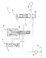
図1は、本発明の一実施例の制御装置が適用された車両用ベルト式無段変速機18を含む動力伝達装置10の骨子図である。この動力伝達装置10はたとえば横置き型FF(フロントエンジン・フロントドライブ)駆動車両に好適に採用されるものであり、走行用の動力源として用いられる内燃機関であるエンジン12を備えている。エンジン12の出力は、トルクコンバータ14から前後進切換装置16、ベルト式無段変速機(CVT)18、減速歯車20を介して差動歯車装置22に伝達され、左右の駆動輪24L、24Rへ分配されるようになっている。上記ベルト式無段変速機18は、エンジン12から左右の駆動輪(たとえば前輪)24L、24Rへ至る動力伝達経路に設けられている。
【0014】
上記トルクコンバータ14は、エンジン12のクランク軸に連結されたポンプ翼車14p、およびタービン軸34を介して前後進切換装置16に連結されたタービン翼車14tと、一方向クラッチを介して非回転部材に回転可能に支持された固定翼車14sとを備えており、流体を介して動力伝達を行うようになっている。また、それ等のポンプ翼車14pおよびタービン翼車14tの間には、それ等を一体的に連結して相互に一体回転させることができるようにするためのロックアップクラッチ(直結クラッチ)26が設けられている。
【0015】
上記前後進切換装置16は、ダブルピニオン型の遊星歯車装置にて構成されており、トルクコンバータ14のタービン軸34はサンギヤ16sに連結され、ベルト式無段変速機18の入力軸36はキャリア16cに連結されている。そして、キャリア16cとサンギヤ16sとの間に配設された前進クラッチ38が係合させられると、前後進切換装置16は一体回転させられてタービン軸34が入力軸36に直結され、前進方向の駆動力が駆動輪24R、24Lに伝達される。また、リングギヤ16rとハウジングとの間に配設された後進ブレーキ40が係合させられるとともに上記前進クラッチ38が開放されると、入力軸36はタービン軸34に対して逆回転させられ、後進方向の駆動力が駆動輪24R、24Lに伝達される。
【0016】
前記ベルト式無段変速機18は、上記入力軸36に設けられた有効径が可変の入力側可変プーリ42と、出力軸44に設けられた有効径が可変の出力側可変プーリ46と、それ等の可変プーリ42、46のV溝に巻き掛けられた伝動ベルト48とを備えており、動力伝達部材として機能する伝動ベルト48と可変プーリ42、46のV溝の内壁面との間の摩擦力を介して動力伝達が行われるようになっている。可変プーリ42、46はそれぞれのV溝幅すなわち伝動ベルト48の掛かり径を変更するための入力側油圧シリンダ42cおよび出力側油圧シリンダ46cを備えて構成されており、入力側可変プーリ42の油圧シリンダ42cに供給或いはそれから排出される作動油の流量が油圧制御回路52内の変速制御弁装置50(図3参照)によって制御されることにより、両可変プーリ42、46のV溝幅が変化して伝動ベルト48の掛かり径(有効径)が変更され、変速比γ(=入力側回転速度NIN/出力側回転速度NOUT )が連続的に変化させられるようになっている。
【0017】
また、出力側可変プーリ46の油圧シリンダ46c内の油圧PB は、可変プーリ46の伝動ベルト48に対する挟圧力および伝動ベルト48の張力にそれぞれ対応するものであって、伝動ベルト48の張力すなわち伝動ベルト48の両可変プーリ42、46のV溝内壁面に対する押圧力に密接に関係しているので、ベルト張力制御圧、ベルト挟圧力制御圧、ベルト押圧力制御圧とも称され得るものであり、伝動ベルト48が滑りを生じないように、油圧制御回路52内の挟圧力制御弁60により調圧されるようになっている。
【0018】
図2および図3は上記油圧制御回路52の一例を示す図であって、図2はベルト張力制御圧の調圧作動に関連する回路、図3は変速比制御に関連する回路をそれぞれ示している。図2において、オイルタンク56に還流した作動油は、エンジン12により駆動される油圧ポンプ54により圧送され、図示しないライン圧調圧弁によりライン圧PL に調圧された後、リニアソレノイド弁58および挟圧力制御弁60に元圧として供給される。リニアソレノイド弁58は、電子制御装置66(図4参照)からの励磁電流が連続的に制御されることにより、油圧ポンプ54から供給された作動油の油圧から、その励磁電流に対応した大きさの制御圧PS を発生させて挟圧力制御弁60に供給する。挟圧力制御弁60は、制御圧PS が高くなるに従って上昇させられる油圧PB を発生させ、出力側可変プーリ46の油圧シリンダ46cに供給することにより、伝動ベルト48が滑りを生じない範囲で可及的にその伝動ベルト48に対する挟圧力すなわち伝動ベルト48の張力が小さくなるようにする。その油圧PB は、その上昇に伴ってベルト挟圧力すなわち可変プーリ42、46と伝動ベルト48との間の摩擦力を増大させる。
【0019】
リニアソレノイド弁58には、カットバック弁62のON時にそれから出力される制御圧PS が供給される油室58aが設けられる一方、カットバック弁62のOFF時には、その油室58aへの制御圧PS の供給が遮断されて油室58aが大気に開放されるようになっており、カットバック弁62のオン時にはオフ時よりも制御圧PS の特性が低圧側へ切り換えられるようになっている。上記カットバック弁62は、前記トルクコンバータ14のロックアップクラッチ26のON(係合)時に、図示しない電磁弁から信号圧PONが供給されることによりONに切り換えられるようになっている。
【0020】
図3において、前記変速制御弁装置50は、前記ライン圧PL の作動油を専ら入力側可変プーリ42の油圧シリンダ42cへ供給し且つその作動油流量を制御することによりアップ方向の変速速度を制御するアップ変速制御弁50U 、およびその油圧シリンダ42cから排出される作動油の流量を制御することによりダウン方向の変速速度を制御するダウン変速制御弁50D から構成されている。このアップ変速制御弁50U は、ライン圧PL を導くライン油路Lと入力側油圧シリンダ42cとの間を開閉するスプール弁子50Uvと、そのスプール弁子50Uvを閉弁方向に付勢するスプリング50Usと、アップ側電磁弁64U から出力される制御圧を導く制御油室50Ucとを備えている。また、ダウン変速制御弁50D は、ドレン油路Dと入力側油圧シリンダ42cとの間を開閉するスプール弁子50Dvと、そのスプール弁子50Dvを閉弁方向に付勢するスプリング50Dsと、ダウン側電磁弁64D から出力される制御圧を導く制御油室50Dcとを備えている。上記アップ側電磁弁64U およびダウン側電磁弁64D は、電子制御装置66によってデューティ駆動されることにより連続的に変化する制御圧を制御油室50Ucおよび制御油室50Dcへ供給し、ベルト式無段変速機18の変速比γをアップ側およびダウン側へ連続的に変化させる。なお、上記ダウン変速制御弁50D には、そのスプール弁子50Dvの閉位置においてライン油路Lと入力側油圧シリンダ42cとの間を僅かな流通断面積の流通路61が形成されるようになっており、上記アップ変速制御弁50U およびダウン変速制御弁50D が共に閉状態であるときには、変速比γを変化させないために、ライン油路Lから絞り63、一方向弁65、上記流通路61を通して作動油が僅かに供給されるようになっている。前記入力側油圧シリンダ42cおよび出力側油圧シリンダ46cは、その回転軸心に対して偏った荷重が加えられることなどにより、シール部材47が摺動部分に設けられているにも拘らず作動油の僅かな漏れが存在するからである。
【0021】
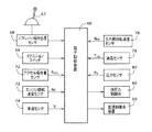
図4の電子制御装置66には、シフトレバー67の操作位置を検出する操作位置検出センサ68からの操作位置PSHを表す信号、イグニションキーにより操作されるイグニションスイッチ69からのイグニションキーのオン操作を表す信号、スロットル弁70の開度を変化させるアクセルペダル71の開度θACC を検出するアクセル操作量センサ72からのアクセル開度θACC を表す信号、エンジン12の回転速度NE を検出するエンジン回転速度センサ73からの回転速度NE を表す信号、車速V(具体的には出力軸44の回転速度NOUT )を検出する車速センサ(出力側回転速度センサ)74からの車速Vを表す信号、入力軸36の入力軸回転速度NINを検出する入力側回転速度センサ76からの入力軸回転速度NINを表す信号、動力伝達装置10すなわちベルト式無段変速機18内の作動油温度TOIL を検出する油温センサ78からの作動油温度TOIL を表す信号、出力側可変プーリ46の油圧シリンダ46cの内圧PB すなわち実際のベルト挟圧力制御圧PB を検出する圧力センサ80からのその油圧PB を表す信号がそれぞれ供給されるようになっている。
【0022】
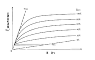
上記電子制御装置66は、CPU、ROM、RAM、入出力インターフェースなどから成る所謂マイクロコンピュータを含んで構成されており、RAMの一時記憶機能を利用しつつROMに予め記憶されたプログラムに従って信号処理を行うことにより、上記無段変速機18の変速制御や挟圧力制御を行うものである。具体的には、変速制御では、たとえば図5に示す予め記憶された関係(マップ)から実際の運転者の要求出力量を表すアクセル操作量すなわちアクセル開度θACC (%)および車速V(出力側回転速度NOUT に対応)に基づいて目標回転速度NIN T を算出し、実際の入力側回転速度NINがその目標回転速度NIN T と一致するように変速制御弁装置50を作動させることにより、入力側可変プーリ42の油圧シリンダ42c内へ供給される作動油或いはその油圧シリンダ42c内から排出される作動油の流量を制御する。上記図5は、たとえば、エンジン12をその出力および燃費が最適となる最適曲線に沿って作動させるために予め求められた関係であって、そのγmax は最大変速比で、γmin は最小変速比である。
【0023】
また、上記電子制御装置66は、ベルト挟圧力制御では、必要かつ十分な必要油圧(理想的なベルト挟圧力に対応する目標油圧)を得るために予め定められた関係(マップ)からベルト式無段変速機18の実際の入力トルクTIN或いは伝達トルクに対応するアクセル操作量θACC および実際の変速比γに基づいてベルト挟圧力制御圧(目標値)を算出し、そのベルト挟圧力制御圧が得られるように油圧制御回路52内の挟圧力制御弁60に調圧させる。
【0024】
図6は、上記電子制御装置66の制御機能の要部すなわちベルト挟圧力制御などを説明する機能ブロック線図である。図6において、変速制御手段88は、車両の走行中において、たとえば図5に示す予め記憶された関係(マップ)から実際のアクセル開度θACC (%)および車速V(出力側回転速度NOUT に対応)に基づいて目標回転速度NIN T を算出し、実際の入力側回転速度NINがその目標回転速度NIN T と一致するように変速制御弁装置50のアップ変速制御弁50U 或いはダウン変速制御弁50D の駆動デューティ比D(%)を決定し、その駆動デューティ比Dで作動させるフィードバック制御を実行することにより、入力側可変プーリ42の油圧シリンダ42cへ供給される作動油或いはその入力側可変プーリ42の油圧シリンダ42cから排出される作動油の流量を制御する。
【0025】
挟圧力制御手段90は、伝動ベルト48のすべりを発生させない範囲で可及的に小さな伝動ベルト48に対する挟圧力を得るために必要かつ十分な必要油圧(理想的なベルト挟圧力に対応する目標油圧)を得るために予め定められた関係(マップ)からベルト式無段変速機18の実際の入力トルクTIN或いは伝達トルクに対応するアクセル操作量θACC および実際の変速比γに基づいてベルト挟圧力制御圧(目標値)PB T を算出し、実際のベルト挟圧力制御圧PB がその目標値PB T と一致するように油圧制御回路52内の挟圧力制御弁60に調圧させる。上記関係は、たとえば定常走行における理論値に基づいて決定されたものである。
【0026】
すべり発生検出手段92は、たとえば逐次求められたベルト式無段変速機18の実際の変速比γが予め設定された判断基準値γB を超えたこと、或いは変速比変化率(変速比変化速度)Δγが予め設定された判断基準値ΔγC を超えたことに基づいて伝動ベルト48のすべりの発生を検出する。上記判断基準値γB は、好適には、ベルト式無段変速機18の機構から許容される最大変速比γmax よりも所定値大きい値すなわちベルト式無段変速機18の機構からはあり得ない値の下限値に設定される。また、上記判断基準値ΔγC は、好適にはベルト式無段変速機18および油圧制御回路52の機構から決まる最大変速比変化率Δγmax よりも所定値大きい値に設定される。
【0027】
挟圧力増加手段94は、伝動ベルト48のすべりが検出されると直ちにそのすべりを防止するために、上記すべり発生検出手段92により伝動ベルト48のすべりが検出される毎に、目標挟圧力PB T に所定値を加えることにより前記挟圧力制御手段90により制御される伝動ベルト48に対する挟圧力を増加させ、その伝動ベルト48に対する挟圧力を増加させる。
【0028】
挟圧状態記憶手段96は、所定の走行期間中たとえば1トリップ(イグニションスイッチオンからオフまで、或いは車両のエンジン始動からそのエンジンの停止まで)の走行中において上記挟圧力増加手段94により増加させられる挟圧力の増加状態を次回の走行時のために記憶する。この記憶内容は上記所定の走行期間の終了時の挟圧力の増加状態となる。上記挟圧状態記憶手段96は、たとえば、前記すべり発生検出手段92により伝動ベルト48のすべりが検出される毎にそのすべりの発生回数nS を計数するすべり発生回数計数手段98と、そのすべり発生回数計数手段98において計数されるすべり発生回数nS を予め設定された上限値nSmaxに制限するすべり発生回数計数値制限手段100とを含み、挟圧力増加手段94による挟圧力の増加状態を示すすべり発生回数nS を記憶する。ここで、すべりの発生回数nS が加算される毎に挟圧力が所定量増加させられてそのすべりの発生回数nS にともなって挟圧力増量分が大きくなることから、上記の上限値nSmaxは、挟圧力増大による伝動ベルト48の耐久性低下を防止するために予め実験的に求められた値たとえば3程度の値に設定される。
【0029】
前回走行中すべり無判定手段102は、予め定められた走行期間内たとえば1トリップまたは所定数のトリップの走行期間内において前記すべり発生検出手段92により伝動ベルト48のすべりが検出されなかったか否かを判定する。すべり発生回数減算手段104は、その前回走行中すべり無判定手段102により伝動ベルト48のすべりが検出されないと判定された場合には、そのすべり発生回数計数手段98の計数内容すなわちすべり発生回数nS を所定量たとえば「1」だけ減算する。
【0030】
また、挟圧力増加手段94は、車両の次回の走行に際して、挟圧状態記憶手段96に記憶されている前回走行時の挟圧力の増加状態すなわちそれに相当するすべり発生回数nS に対応する量だけ、挟圧力制御手段90による挟圧力に加えることにより、伝動ベルト48に対する挟圧力を増加させる。
【0031】
また、上記挟圧力増加手段94は、前記すべり発生回数計数手段98によって計数された伝動ベルト48のすべり回数nS が所定値たとえば「1」以下である場合には、予め設定された基礎増量値Aだけ伝動ベルト48に対する挟圧力を増加させ、その所定値を越えた場合には、その基礎増量値Aに加えてその基礎増量値Aよりも小さく予め設定された比例増量値Bだけすべり回数に応じて順次増加させる。
【0032】
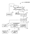
図7は、電子制御装置66の制御作動の要部を説明するフローチャートであって、所定のサイクルタイムで繰り返し実行されるものである。ステップ(以下、ステップを省略する)SA1において、すべり回数積算カウンタCS のデクリメントの実施を示すフラグFD の内容が「1」であるか否かが判断される。このフラグFD は、その回数積算カウンタCS の誤減算防止のために設けられたものであり、たとえばイグニションスイッチ69のオフ操作によりクリアされる。当初はこのSA1の判断が否定されるので、SA2において、先(前回)のトリップにおいて伝動ベルト48のすべりが発生したことを示すすべり発生履歴フラグFS の内容が「1」であるか否かが判断される。このSA2の判断が否定されると、SA3において、今回のトリップにおいてすべり無しトリップ回数積算カウンタCnos のインクリメントが実施されたか否かが判断される。このSA3の判断が否定される場合は、SA4において、すべり無しトリップ回数積算カウンタCnos の内容に「1」が加算されることによりそのすべり無しトリップ回数積算カウンタCnos がインクリメントされるとともに、SA5においてベルトすべり発生履歴フラグFS の内容が「0」とされることによりクリアされる。
【0033】
しかし、上記SA2、SA3の判断のいずれかが肯定された場合は、すべり無しトリップ回数積算カウンタCnos をインクリメントするためのSA4が実行されないで、上記SA5が直接実行されてベルトすべり発生履歴フラグFS がクリアされる。
【0034】
続いて、前回走行中すべり無判定手段102に対応するSA6では、すべり無しトリップ回数積算カウンタCnos の内容が所定の判定値たとえば「3」以上となったか否かすなわち3トリップの走行期間中の伝動ベルト48のすべりが検出されなかったか否かが判断される。この判定値は、伝動ベルト48のすべりを十分に発生させない挟圧力状態であることを確認するために予め設定された走行期間に対応するものであり、予め実験的に求められたものである。次いでSA7では、すべり回数積算カウンタCS の内容nS が「0」よりも大きいか否かすなわちすべり回数積算カウンタCS 内にすべり回数が計数されているか否かが判断される。
【0035】
上記SA6およびSA7の判断がいずれも肯定された場合は、前記すべり発生回数減算手段104に対応するSA8において、すべり回数積算カウンタCS がデクリメントされてその内容nS がそれまでよりも「1」だけ減算されるとともに、すべり回数積算カウンタCS のデクリメントの実施を示すフラグFD の内容が「1」にセットされる。本実施例では、3トリップの走行期間中の伝動ベルト48のすべりが検出されない場合にすべり回数積算カウンタCS がデクリメントされる。しかし、上記SA6およびSA7の判断のいずれかが否定された場合は、上記SA8の次のSA9以下が直接実行される。
【0036】
SA9およびSA10は、前記すべり発生検出手段92に対応するものである。先ずSA9では、発進時に伝動ベルト48のすべりが発生したか否かが、たとえばベルト式無段変速機18の変速比γが予め設定されたすべり判定値γB を超えたか否かに基づいて判断される。このSA9の判断が否定された場合には、SA10において、走行中に伝動ベルト48のすべりが発生したか否かが、たとえば変速比変化率Δγが予め設定されたすべり判定値ΔγC を超えたか否かに基づいて判断される。
【0037】
上記SA9またはSA10の判断が肯定された場合は、伝動ベルト48のすべりが発生した状態であるので、前記すべり発生回数計数手段98に対応するSA11において、SA9またはSA10において検出されたすべりの発生回数を計数するためのすべり回数積算カウンタCS の計数内容nS に「1」が加算されることによってすべり回数積算カウンタCS がインクリメントされる。同時に、伝動ベルト48のすべりが発生したことを示すフラグすべり発生履歴フラグFS の内容が「1」にセットされるとともに、すべり無しトリップ回数積算カウンタCnos の内容が「0」にクリアされる。
【0038】
次いで、前記すべり発生回数計数値制限手段100に対応するSA12およびSA13が実行される。すなわち、SA12において、すべり回数積算カウンタCS の計数内容nS が予め設定された制限値nSmax以上となったか否かが判断され、そのSA12の判断が否定された場合はSA13が実行されないが、そのSA12の判断が肯定された場合は、SA13においてすべり回数積算カウンタCS の計数内容nS が予め設定された制限値nSmaxとされる。しかし、前記SA9およびSA10の判断が否定された場合は、上記SA11乃至SA13が実行されないで、前記挟圧力増加手段94に対応するSA14乃至SA17が実行される。
【0039】
SA14では、すべり回数積算カウンタCS の計数内容nS が「1」であるか否かが判断される。このSA14の判断が否定される場合はSA15が実行されないが、肯定される場合はSA15において、前記挟圧力制御手段90において用いられるベルト挟圧力PB に加えられるベルト挟圧力増加値PUPが基本増加値Aに設定される。続くSA16では、すべり回数積算カウンタCS の計数内容nS が「2」以上であるか否かが判断される。このSA16の判断が否定される場合はSA17が実行されないが、肯定される場合はSA17において、数式1から実際の計数内容nS に基づいてベルト挟圧力増加値PUPが算出される。たとえば、すべり回数積算カウンタCS の計数内容nS が「0」である場合はSA14およびSA16の判断がいずれも否定されるので、ベルト挟圧力増加値PUPが零とされるが、計数内容nS が「1」である場合は、有効にすべりを収束させるために比較的大きなベルト挟圧力増加値PUP(=A)とされ、計数内容nS が「2」である場合は、ベルト挟圧力増加値PUPが(A+B)とされる。数式1において、Bは計数内容nS の増加毎に増加させられる比例増加値であり、基本増加値Aよりも小さい値(B<A)に設定されている。
【0040】
PUP=A+(nS −1)×B ・・・(1)
【0041】
したがって、上記挟圧力増加手段94に対応するSA14乃至SA17では、所定の走行期間中において伝動ベルト48のすべりが検出されてすべり回数積算カウンタCS の計数内容nS が増加させられると、その増加毎にベルト挟圧力増加値PUPが増加させられて上記伝動ベルト48の挟圧力が増加させられる。また、車両の走行開始に際してすなわち次回の走行に先立ってイグニションスイッチ69がオン操作されると、前回までの走行期間中においてすべり回数積算カウンタCS (挟圧状態記憶手段96)に記憶されている計数内容nS に応じてベルト挟圧力増加値PUPが算出され、そのベルト挟圧力増加値PUPにより伝動ベルト48の挟圧力が増加させられる。
【0042】
上述のように、本実施例によれば、次回の走行に際しては、挟圧状態記憶手段96(SA11)に記憶されている前回走行時の挟圧力の増加状態に対応して挟圧力増加手段94(SA14乃至SA17)により伝動ベルト48に対する挟圧力が増加させられることから、伝動ベルト48のすべりが発生した前回走行時後の次回走行においてその伝動ベルト48の再すべりが防止される。したがって、すべりに起因する伝動ベルト48の耐久性の低下が防止される。
【0043】
また、本実施例によれば、伝動ベルト48のすべりの発生を検出するすべり発生検出手段92(SA9、SA10)と、そのすべり発生検出手段92により伝動ベルト48のすべりが検出される毎にその伝動ベルト48に対する挟圧力を増加させる挟圧力増加手段94とが、さらに設けられていることから、挟圧力増加手段94によって、すべり発生検出手段92により伝動ベルト48のすべりが検出される毎にその伝動ベルト48に対する挟圧力が増加させられるので、直ちに伝動ベルト48のすべりが解消される。
【0044】
また、本実施例によれば、挟圧状態記憶手段96は、すべり発生検出手段92により伝動ベルト48のすべりの発生が検出される毎にすべりの発生回数を計数するすべり発生回数計数手段98(SA11)を含み、所定回数の走行期間(トリップ)内においてすべり発生検出手段92により伝動ベルト48のすべりが検出されないか否かを判定する前回走行中すべり無判定手段102(SA6)と、その前回走行中すべり無判定手段102により伝動ベルト48のすべりが検出されないと判定された場合には、そのすべり発生回数計数手段98の計数内容nS を減算するすべり発生回数減算手段104(SA8)とが、さらに設けられ、挟圧力増加手段94は、上記すべり発生回数計数手段98の計数内容nS に応じて伝動ベルト48の増加量を調節するものであることから、所定回数の走行期間内においてすべり発生検出手段92により伝動ベルト48のすべりが検出されない場合には、伝動ベルト48のすべりが発生しない範囲で挟圧力増加手段94による挟圧力の増加量が減少させられるので、伝動ベルト48の耐久性が一層高められる。
【0045】
また、本実施例によれば、車両の1回の走行期間として、イグニションスイッチ69のオン操作による車両のエンジン始動からイグニションスイッチ69のオフ操作によるそのエンジンの停止までの車両走行期間であるトリップが用いられているので、比較的長期間におけるベルト式無段変速機18のすべり状態に基づいてすべり無し判定が行われ得るので、そのベルト式無段変速機18のすべり状態の判定の信頼性が高められる。
【0046】
また、本実施例によれば、すべり発生回数計数手段98において計数されるすべり発生回数nS を予め設定された上限値nSmax に制限するすべり発生回数計数値制限手段100(SA12、SA13)が設けられていることから、すべり発生回数計数手段98において計数されるすべり発生回数nS が予め設定された上限値nSmaxに制限されるので、伝動ベルト48に対して過大な挟圧力が付与されることによる耐久性低下が防止される。
【0047】
また、本実施例によれば、挟圧力増加手段94は、すべり発生回数計数手段98によって計数された伝動ベルト48のすべり回数nS がたとえば所定値「1」以下である場合には、予め設定された基礎増量値Aだけ挟圧力PB を増加させ、その所定値「1」を越えた場合には、その基礎増量値Aよりも小さく予め設定された比例増量値Bだけすべり回数に応じて順次増加させるものであるので、最初の伝動ベルト48のすべり発生時において確実にすべりが収束させられ、伝動ベルト48の耐久性が高められる利点がある。
【0048】
以上、本発明の一実施例を図面に基づいて説明したが、本発明はその他の態様においても適用される。
【0049】
たとえば、前述の実施例においては、伝動ベルト48が巻きかけられた1対の可変プーリ42、46を備えた所謂ベルト式無段変速機18が用いられていたが、トロイダル型無段変速機などの他の無段変速機にも本発明は適用され得る。要するに、入力側回転体および出力側回転体の間に介在させられて挟圧される動力伝達部材のその入力側回転体および出力側回転体に対する接触位置が変更されることにより変速比が無段階に変化させられる無段変速機であればよいのである。
【0050】
また、前述の実施例において、車両の1回の走行期間として前記トリップが用いられていたが、車両の発進から停止までの走行期間、予め設定された走行距離を走行する期間などが用いられてもよい。
【0051】
また、前述の実施例において、すべり発生回数減算手段104は、3回のトリップ期間内において伝動ベルト48のスリップが発生しないことを条件としてすべり発生回数計数手段98の計数値nS から「1」を減算するものであったが、1回以上の所定回数の走行期間内においてスリップが発生しないことを条件としてもよい。
【0052】
また、前述の実施例において、挟圧力増加手段94は数式1から実際のスリップ発生回数nS に基づいて挟圧力増加値PUPを算出していたが、必ずしも数式1が用いられなくてもよい。
【0053】
以上、本発明の実施例を図面に基づいて詳細に説明したが、これはあくまでも一実施形態であり、本発明は当業者の知識に基づいて種々の変更,改良を加えた態様で実施することができる。
【図面の簡単な説明】
【図1】本発明の一実施例の制御装置が適用された車両用駆動装置の骨子図である。
【図2】図1の車両用動力伝達装置におけるベルト式無段変速機を制御するための油圧制御回路の要部を示す図であって、ベルト張力制御に関連する部分を示す図である。
【図3】図1の車両用動力伝達装置におけるベルト式無段変速機を制御するための油圧制御回路の要部を示す図であって、変速比制御に関連する部分を示す図でる。
【図4】図1の実施例の制御装置の電気的構成を簡単に説明する図である。
【図5】図4の電子制御装置が実行する変速比制御において目標回転速度を決定するために用いられる予め記憶された関係を示す図である。
【図6】図4の電子制御装置の制御機能の要部を説明する機能ブロック線図である。
【図7】図6の電子制御装置の制御作動の要部を説明するフローチャートであって、挟圧状態記憶手段などの対応するルーチンを示す図である。
【図8】図4の電子制御装置の制御作動の要部を説明するフローチャートであって、挟圧力増加手段に対応するルーチンを示す図である。
【符号の説明】
18:ベルト式無段変速機(無段変速機)
48:伝動ベルト(動力伝達部材)
66:電子制御装置
92:すべり発生検出手段
94:挟圧力増加手段
96:挟圧状態記憶手段
98:すべり発生回数計数手段
104:すべり発生回数減算手段[0001]
【Technical field】
The present invention relates to a control device for a continuously variable transmission for a vehicle, and more particularly to a technique for preventing a decrease in durability caused by slippage of a power transmission member.
[0002]
[Prior art]
In a continuously variable transmission for a vehicle that transmits power via friction with a power transmission member for transmitting power, when slippage of the power transmission member is detected during a predetermined travel period, the power transmission member A control device for a continuously variable transmission for a vehicle in which the clamping pressure is increased has been proposed. For example, a control device for a continuously variable transmission for a vehicle described in JP-A-9-324853. According to this, in a belt-type continuously variable transmission in which a transmission belt is wound around a pair of variable pulleys having variable effective diameters, slippage (slip) of the transmission belt is determined when the engine load increases such as when the vehicle starts. Then, the clamping pressure of the transmission belt is immediately increased, and when the slippage of the transmission belt is not determined, the transmission belt is returned to the normal belt clamping pressure determined by the input torque and the gear ratio.
[0003]
[Problems to be Solved by the Invention]
However, according to the above conventional control device for a continuously variable transmission for a vehicle, when the slip of the power transmission member is not determined, the belt is returned to the normal belt clamping pressure, so that the previous slip occurred during traveling of the vehicle. When the conditions are close, slippage of the power transmission member is likely to occur again, and there is a disadvantage that the life or durability of the power transmission member is reduced.
[0004]
The present invention has been made against the background of the above circumstances, and an object of the present invention is to provide a control device for a continuously variable transmission for a vehicle in which re-sliding of a power transmission member is suitably prevented. .
[0005]
[Means for Solving the Problems]
In order to achieve this object, the gist of the present invention is that in a continuously variable transmission for a vehicle that transmits power via friction with a power transmission member for transmitting power, in a predetermined traveling period. When the slip of the power transmission member is detected, the control device for a continuously variable transmission for a vehicle increases the clamping pressure on the power transmission member, and (a) the clamping pressure stores the increase state of the clamping pressure A state storage means, and (b) a nipping pressure increase that increases a nipping pressure with respect to the power transmission member in response to the increase state of the nipping pressure during the previous travel stored in the nipping state storage means in the next travel Means and, ( c ) Slip occurrence detecting means for detecting the occurrence of slip of the power transmission member, d The clamping state storage means includes a slip occurrence number counting means for counting the number of occurrences of slip each time the occurrence of slip of the power transmission member is detected by the slip occurrence detecting means, e ) When it is assumed that one running period is from the start of the engine of the vehicle by turning on the ignition switch to the stopping of the engine by turning off the ignition switch, the slip occurrence detecting means performs the above-described slip generation detecting means within one or a predetermined number of running periods. When the slip of the power transmission member is not detected, a slip occurrence number subtracting means for subtracting the count content of the slip occurrence number counting means is further provided ( f ) The clamping pressure increasing means adjusts the amount of increase in the clamping pressure of the power transmission member according to the count contents of the slip occurrence counting means.There is.
[0006]
【The invention's effect】
In this way, at the time of the next travel, the clamping pressure on the power transmission member is increased by the clamping pressure increasing means corresponding to the increasing state of the clamping pressure at the previous travel stored in the clamping pressure storage means. Therefore, the power transmission member is prevented from slipping again in the next travel after the previous travel when the power transmission member slipped. Accordingly, a decrease in durability of the power transmission member due to the slip is prevented.Further, when slippage of the power transmission member is not detected by the slip generation detection means within one or a predetermined number of traveling periods, increase of the clamping pressure by the clamping pressure increase means within a range where no slippage of the power transmission member occurs. Since the amount is reduced, the durability of the power transmission member is further enhanced.
[0007]
Other aspects of the invention
Preferably, slip generation detecting means for detecting the occurrence of slip of the power transmission member, and a clamping pressure applied to the power transmission member each time the slip of the power transmission member is detected by the slip generation detection means. A clamping pressure increasing means for increasing is further provided. In this way, the nipping pressure increasing means increases the nipping pressure against the power transmission member every time the slip generation detecting means detects the slip of the power transmission member, so that the power transmission member frequently slides again. Occurrence is eliminated.
[0009]
Preferably, the travel period is a vehicle travel period from the start of the engine of the vehicle by turning on the ignition switch to the stop of the engine by turning off the ignition switch. In this way, the non-slip determination can be made based on the slip state of the continuously variable transmission over a relatively long period of time, so the reliability of the determination of the slip state of the continuously variable transmission can be improved.
[0010]
Preferably, there is provided a slip occurrence count value limiting means for limiting the slip occurrence count counted by the slip occurrence count counting means to a preset upper limit value. In this way, the number of slip occurrences counted by the slip occurrence number counting means is limited to a preset upper limit value, thereby preventing the clamping force from becoming excessive and impairing the durability of the power transmission member. Is done.
[0011]
Preferably, the clamping pressure increasing means sets a preset basic increase when the number of slips of the power transmission member counted by the slip occurrence number counting means is a predetermined value, for example, “1” or less. When the clamping pressure is increased by a value and exceeds the predetermined value, the proportional increase value smaller than the basic increase value is sequentially increased according to the number of slips. In this way, there is an advantage that the slip is surely converged when the first power transmission member slips and the durability of the power transmission member is enhanced.
[0012]
BEST MODE FOR CARRYING OUT THE INVENTION
Hereinafter, embodiments of the present invention will be described in detail with reference to the drawings.
[0013]
FIG. 1 is a skeleton diagram of a
[0014]
The
[0015]
The forward /
[0016]
The belt type continuously
[0017]
The hydraulic pressure P in the
[0018]
2 and 3 are diagrams showing an example of the
[0019]
The
[0020]
In FIG. 3, the shift
[0021]
4 includes an operation position P from an operation
[0022]
The
[0023]
In addition, the
[0024]
FIG. 6 is a functional block diagram for explaining a main part of the control function of the
[0025]
The clamping pressure control means 90 is necessary and sufficient necessary oil pressure (a target hydraulic pressure corresponding to an ideal belt clamping pressure) to obtain a clamping pressure with respect to the
[0026]
The slip
[0027]
In order to prevent slipping immediately after the slippage of the
[0028]
The pinching state storage means 96 is increased by the pinching pressure increasing means 94 during a predetermined travel period, for example, during one trip (from ignition switch on to off, or from vehicle engine start to engine stop). The increase state of the clamping pressure is stored for the next driving. This stored content is an increased state of the clamping pressure at the end of the predetermined traveling period. For example, each time the slippage of the
[0029]
The non-slip determining means 102 during the previous run determines whether or not the slip of the
[0030]
Further, when the vehicle travels next time, the clamping pressure increasing means 94 increases the clamping pressure during the previous travel stored in the clamping pressure state storage means 96, that is, the number n of slip occurrences corresponding thereto.SIs added to the clamping pressure by the clamping pressure control means 90 by an amount corresponding to the above, thereby increasing the clamping pressure on the
[0031]
Further, the clamping
[0032]
FIG. 7 is a flowchart for explaining a main part of the control operation of the
[0033]
However, if either of the above determinations of SA2 and SA3 is affirmed, the non-slip trip count integration counter CnosSA4 for incrementing is not executed, SA5 is directly executed, and the belt slip occurrence history flag F is executed.SIs cleared.
[0034]
Subsequently, in SA6 corresponding to the
[0035]
If the determinations at SA6 and SA7 are both affirmative, at SA8 corresponding to the slip occurrence frequency subtracting means 104, the slip frequency counter CSIs decremented and its contents nSIs subtracted by “1” than before, and the slip count counter CSFlag F to indicate the decrement ofDIs set to “1”. In the present embodiment, when the slip of the
[0036]
SA9 and SA10 correspond to the slip
[0037]
If the determination at SA9 or SA10 is affirmative, the
[0038]
Next, SA12 and SA13 corresponding to the slip occurrence count value limiting means 100 are executed. That is, in SA12, the slip counter CSCounting contents of nSIs a preset limit value nSmaxIf it is determined whether or not the determination is SA12 and the determination of SA12 is negative, SA13 is not executed, but if the determination of SA12 is affirmative, the slip count counter C is determined in SA13.SCounting contents of nSIs a preset limit value nSmaxIt is said. However, if the determinations at SA9 and SA10 are negative, SA11 to SA13 are not executed, and SA14 to SA17 corresponding to the clamping
[0039]
In SA14, the slip counter CSCounting contents of nSIs determined to be “1”. If the determination of SA14 is negative, SA15 is not executed. If the determination is positive, in SA15, the belt clamping pressure P used in the clamping pressure control means 90 is determined.BThe belt clamping pressure increase value P applied toUPIs set to the basic increase value A. In subsequent SA16, the slip counter CSCounting contents of nSIs determined to be greater than or equal to “2”. If the determination of SA16 is negative, SA17 is not executed. If the determination is positive, in SA17, the actual count content n is calculated from Equation 1.SBased on the belt clamping pressure increase value PUPIs calculated. For example, the slip counter CSCounting contents of nSWhen SA is “0”, the determinations of SA14 and SA16 are both denied, so the belt clamping pressure increase value PUPIs set to zero, but the counted content nSIs “1”, a relatively large belt clamping pressure increase value P for effectively converging the slip.UP(= A) and the content of counting nSIs “2”, the belt clamping pressure increase value PUPIs (A + B). In
[0040]
PUP= A + (nS-1) x B (1)
[0041]
Accordingly, in SA14 to SA17 corresponding to the clamping
[0042]
As described above, according to the present embodiment, in the next traveling, the clamping
[0043]
Further, according to the present embodiment, the slip occurrence detecting means 92 (SA9, SA10) for detecting the occurrence of the slip of the
[0044]
In addition, according to the present embodiment, the clamping
[0045]
Further, according to the present embodiment, a trip that is a vehicle travel period from the start of the engine of the vehicle by turning on the
[0046]
Further, according to the present embodiment, the number n of slip occurrences counted by the slip occurrence number counting means 98 is shown.SIs a preset upper limit value nSmaxSince the slip occurrence number count value limiting means 100 (SA12, SA13) is provided, the slip occurrence number n counted by the slip occurrence count counting means 98 is provided.SIs the preset upper limit value nSmaxTherefore, a decrease in durability due to an excessive clamping pressure applied to the
[0047]
Further, according to the present embodiment, the clamping
[0048]
As mentioned above, although one Example of this invention was described based on drawing, this invention is applied also in another aspect.
[0049]
For example, in the above-described embodiment, the so-called belt type continuously
[0050]
In the above-described embodiment, the trip is used as a single travel period of the vehicle. However, a travel period from start to stop of the vehicle, a period of traveling a preset travel distance, and the like are used. Also good.
[0051]
Further, in the above-described embodiment, the slip occurrence number subtracting means 104 counts the value n of the slip occurrence number counting means 98 on condition that no slippage of the
[0052]
Further, in the above-described embodiment, the clamping
[0053]
As mentioned above, although the Example of this invention was described in detail based on drawing, this is an embodiment to the last, and this invention implements in the aspect which added various change and improvement based on the knowledge of those skilled in the art. Can do.
[Brief description of the drawings]
FIG. 1 is a schematic diagram of a vehicle drive device to which a control device according to an embodiment of the present invention is applied.
FIG. 2 is a diagram showing a main part of a hydraulic control circuit for controlling a belt type continuously variable transmission in the vehicle power transmission device of FIG. 1, and showing a portion related to belt tension control;
3 is a diagram showing a main part of a hydraulic control circuit for controlling a belt-type continuously variable transmission in the vehicle power transmission device of FIG. 1, and showing a portion related to gear ratio control. FIG.
4 is a diagram for simply explaining the electrical configuration of the control device of the embodiment of FIG. 1; FIG.
FIG. 5 is a view showing a prestored relationship used for determining a target rotation speed in speed ratio control executed by the electronic control unit of FIG. 4;
6 is a functional block diagram illustrating a main part of a control function of the electronic control device of FIG. 4;
7 is a flowchart for explaining a main part of the control operation of the electronic control device of FIG. 6, and shows a corresponding routine such as a pinching state storage unit.
FIG. 8 is a flowchart for explaining a main part of the control operation of the electronic control device of FIG. 4 and shows a routine corresponding to the clamping pressure increasing means.
[Explanation of symbols]
18: Belt type continuously variable transmission (continuously variable transmission)
48: Transmission belt (power transmission member)
66: Electronic control device
92: Slip occurrence detection means
94: Nipping pressure increasing means
96: Clamping state storage means
98: Means for counting slip occurrence
104: Slip occurrence number subtraction means
Claims (1)
前記挟圧力の増加状態を記憶する挟圧状態記憶手段と、
次回の走行に際して、該挟圧状態記憶手段に記憶されている前回走行時の挟圧力の増加状態に対応して前記動力伝達部材に対する挟圧力を増加させる挟圧力増加手段と、
前記動力伝達部材のすべりの発生を検出するすべり発生検出手段と
を、含み、
前記挟圧状態記憶手段は、前記すべり発生検出手段により前記動力伝達部材のすべりの発生が検出される毎にすべりの発生回数を計数するすべり発生回数計数手段を含み、
イグニションスイッチのオン操作による車両のエンジン始動から該イグニションスイッチのオフ操作によるエンジンの停止までを1回の走行期間としたとき、1回または所定回数の走行期間内において前記すべり発生検出手段により前記動力伝達部材のすべりが検出されない場合には、該すべり発生回数計数手段の計数内容を減算するすべり発生回数減算手段が、さらに設けられ、
前記挟圧力増加手段は、前記すべり発生回数計数手段の計数内容に応じて前記動力伝達部材の挟圧力の増加量を調節することを特徴とする車両用無段変速機の制御装置。In a continuously variable transmission for a vehicle that transmits power via friction with a power transmission member for transmitting power, when slippage of the power transmission member is detected during a predetermined travel period, the power transmission member A control device for a continuously variable transmission for a vehicle of a type that increases the clamping pressure,
Clamping state storage means for storing an increase state of the clamping pressure;
A clamping pressure increasing means for increasing a clamping pressure on the power transmission member in response to an increased state of the clamping pressure during the previous travel stored in the clamping pressure storage means during the next travel ;
Slip generation detecting means for detecting occurrence of slip of the power transmission member;
Including,
The pinching state storage means includes slip occurrence number counting means for counting the number of occurrences of slip every time the occurrence of slip of the power transmission member is detected by the slip occurrence detecting means,
When the period from the start of the engine of the vehicle by turning on the ignition switch to the stop of the engine by turning off the ignition switch is defined as one traveling period, the power is detected by the slip generation detecting means within one or a predetermined number of traveling periods. When the slip of the transmission member is not detected, a slip occurrence number subtracting means for subtracting the count content of the slip occurrence number counting means is further provided,
The control apparatus for a continuously variable transmission for a vehicle, wherein the clamping pressure increasing means adjusts an increase amount of the clamping pressure of the power transmission member in accordance with a count content of the slip occurrence number counting means .
Priority Applications (4)
| Application Number | Priority Date | Filing Date | Title |
|---|---|---|---|
| JP2000151303A JP3750488B2 (en) | 2000-05-23 | 2000-05-23 | Control device for continuously variable transmission for vehicle |
| US09/859,494 US6461261B2 (en) | 2000-05-23 | 2001-05-18 | Control apparatus and method of continuously variable transmission |
| DE60144080T DE60144080D1 (en) | 2000-05-23 | 2001-05-22 | Control system and method for a continuously variable transmission |
| EP01112496A EP1158214B1 (en) | 2000-05-23 | 2001-05-22 | Control system and method for a continuously variable transmission |
Applications Claiming Priority (1)
| Application Number | Priority Date | Filing Date | Title |
|---|---|---|---|
| JP2000151303A JP3750488B2 (en) | 2000-05-23 | 2000-05-23 | Control device for continuously variable transmission for vehicle |
Publications (2)
| Publication Number | Publication Date |
|---|---|
| JP2001330119A JP2001330119A (en) | 2001-11-30 |
| JP3750488B2 true JP3750488B2 (en) | 2006-03-01 |
Family
ID=18656886
Family Applications (1)
| Application Number | Title | Priority Date | Filing Date |
|---|---|---|---|
| JP2000151303A Expired - Lifetime JP3750488B2 (en) | 2000-05-23 | 2000-05-23 | Control device for continuously variable transmission for vehicle |
Country Status (4)
| Country | Link |
|---|---|
| US (1) | US6461261B2 (en) |
| EP (1) | EP1158214B1 (en) |
| JP (1) | JP3750488B2 (en) |
| DE (1) | DE60144080D1 (en) |
Families Citing this family (22)
| Publication number | Priority date | Publication date | Assignee | Title |
|---|---|---|---|---|
| DE10310831A1 (en) * | 2002-04-10 | 2003-11-06 | Luk Lamellen & Kupplungsbau | Vehicle drive train, includes divided flywheel with relatively-rotating weights between crank shaft and input to gearbox |
| DE50301752D1 (en) * | 2002-04-10 | 2005-12-29 | Luk Lamellen & Kupplungsbau | METHOD FOR DETERMINING THE SPEED OF A COMPONENT |
| US20040055803A1 (en) * | 2002-09-24 | 2004-03-25 | Patmont Motor Werks | Variable speed transmission for scooter |
| JP3731746B2 (en) | 2002-09-26 | 2006-01-05 | 日産自動車株式会社 | Control device for engine and belt type continuously variable transmission |
| JP3786198B2 (en) * | 2002-09-30 | 2006-06-14 | ジヤトコ株式会社 | Transmission hydraulic control device for belt type continuously variable transmission |
| US7666110B2 (en) | 2003-03-26 | 2010-02-23 | Toyota Jidosha Kabushiki Kaisha | Control system for power transmission mechanism |
| US7832297B2 (en) | 2005-04-19 | 2010-11-16 | Hewatt Chris B | Method and apparatus for gyroscopic propulsion |
| JP2007232147A (en) * | 2006-03-02 | 2007-09-13 | Yamaha Motor Co Ltd | Vehicle |
| JP4593500B2 (en) * | 2006-03-16 | 2010-12-08 | ジヤトコ株式会社 | Control device for continuously variable transmission |
| JP4238906B2 (en) * | 2006-10-13 | 2009-03-18 | トヨタ自動車株式会社 | Control device for continuously variable transmission, control method, program for realizing the method, and recording medium recording the program |
| JP5060371B2 (en) * | 2008-04-07 | 2012-10-31 | トヨタ自動車株式会社 | Power output device and vehicle |
| US8060288B2 (en) | 2009-03-20 | 2011-11-15 | Toyota Motor Engineering & Manufacturing North America, Inc. | Control system and method to inhibit automatic transmission downshifting during trailer sway |
| US8965645B2 (en) * | 2009-06-25 | 2015-02-24 | Toyota Motor Engineering & Manufacturing North America, Inc. | Method and system for automated control of transmission ratio change |
| US8585551B2 (en) | 2010-01-27 | 2013-11-19 | Toyota Motor Engineering & Manufacturing North America, Inc. | Method and system for adaptive continuously variable transmission gear ratio control |
| US8751124B2 (en) * | 2010-03-02 | 2014-06-10 | Toyota Motor Engineering & Manufacturing North America, Inc. | Method and system for adaptive electronic driveforce unit control |
| US8655569B2 (en) * | 2010-03-02 | 2014-02-18 | Toyota Motor Engineering & Manufacturing North America, Inc. | Method and system for varying an output of a driveforce unit based on load data |
| US9804227B2 (en) * | 2010-09-24 | 2017-10-31 | Ford Global Technologies, Llc | Electric machine fast transient condition detection |
| JP5699646B2 (en) * | 2011-02-02 | 2015-04-15 | 日本精工株式会社 | Continuously variable transmission |
| US9441733B2 (en) * | 2012-06-08 | 2016-09-13 | Jatco Ltd | Continuously variable transmission and a hydraulic control method thereof |
| US9037370B2 (en) * | 2012-06-15 | 2015-05-19 | Allison Transmission, Inc. | Multi-plexing clutch logic control of a multi-mode transmission |
| JP5852554B2 (en) * | 2012-12-21 | 2016-02-03 | 本田技研工業株式会社 | Hydraulic transmission device for automatic transmission |
| JP5937628B2 (en) * | 2014-01-17 | 2016-06-22 | ジヤトコ株式会社 | Continuously variable transmission and its safety factor correction method |
Family Cites Families (13)
| Publication number | Priority date | Publication date | Assignee | Title |
|---|---|---|---|---|
| US4322798A (en) * | 1978-02-16 | 1982-03-30 | Bales-Mccoin Research, Inc. | Traction pressure control system |
| JP2661346B2 (en) | 1989-09-18 | 1997-10-08 | トヨタ自動車株式会社 | Hydraulic control device for continuously variable transmission for vehicles |
| JPH03129158A (en) | 1989-10-11 | 1991-06-03 | Nissan Motor Co Ltd | Continuously variable transmission |
| JPH0464760A (en) | 1990-06-30 | 1992-02-28 | Mazda Motor Corp | Control device for continuously variable transmission |
| JP3209050B2 (en) | 1995-07-04 | 2001-09-17 | ヤマハ株式会社 | Controller device |
| JP3129158B2 (en) | 1995-07-14 | 2001-01-29 | 凸版印刷株式会社 | Waterless offset printing press |
| JP3299661B2 (en) * | 1995-08-10 | 2002-07-08 | 本田技研工業株式会社 | Belt type continuously variable transmission |
| JP3505917B2 (en) | 1996-06-05 | 2004-03-15 | 日産自動車株式会社 | Line pressure control device for V-belt type continuously variable transmission |
| DE19638277A1 (en) * | 1996-09-19 | 1998-03-26 | Bosch Gmbh Robert | Device and method for operating a belt transmission |
| DE19650218A1 (en) * | 1996-12-04 | 1998-06-10 | Zahnradfabrik Friedrichshafen | Method for controlling a CVT |
| NL1008347C1 (en) * | 1998-02-19 | 1998-03-16 | Doornes Transmissie Bv | Continuously Variable Transmission. |
| DE19937472C1 (en) * | 1999-08-07 | 2000-11-30 | Zahnradfabrik Friedrichshafen | Variator slip regulation method for automobile continuously variable transmission has slip counter of evalaution module indexed simultaneous with incrementation of slip counter field for weighting slip duration and intensity |
| US6387009B1 (en) * | 1999-11-22 | 2002-05-14 | General Motors Corporation | Traction drive with slip control and method of controlling the slip |
-
2000
- 2000-05-23 JP JP2000151303A patent/JP3750488B2/en not_active Expired - Lifetime
-
2001
- 2001-05-18 US US09/859,494 patent/US6461261B2/en not_active Expired - Lifetime
- 2001-05-22 EP EP01112496A patent/EP1158214B1/en not_active Expired - Lifetime
- 2001-05-22 DE DE60144080T patent/DE60144080D1/en not_active Expired - Lifetime
Also Published As
| Publication number | Publication date |
|---|---|
| EP1158214A3 (en) | 2008-07-23 |
| US6461261B2 (en) | 2002-10-08 |
| EP1158214A2 (en) | 2001-11-28 |
| EP1158214B1 (en) | 2011-02-23 |
| JP2001330119A (en) | 2001-11-30 |
| DE60144080D1 (en) | 2011-04-07 |
| US20010049316A1 (en) | 2001-12-06 |
Similar Documents
| Publication | Publication Date | Title |
|---|---|---|
| JP3750488B2 (en) | Control device for continuously variable transmission for vehicle | |
| JP3855599B2 (en) | Control device for continuously variable transmission for vehicle | |
| JP3750523B2 (en) | Shift control device for continuously variable transmission for vehicle | |
| JP4200952B2 (en) | Vehicle control apparatus equipped with continuously variable transmission | |
| US8175777B2 (en) | Control apparatus, control method, and computer-readable storage medium for continuously variable transmission | |
| JP3730204B2 (en) | Belt slip prevention system for belt type continuously variable transmission | |
| JP4238906B2 (en) | Control device for continuously variable transmission, control method, program for realizing the method, and recording medium recording the program | |
| CN101490443B (en) | Control apparatus and control method of continuously variable transmission | |
| JP4310888B2 (en) | Vehicle clutch control device | |
| JP2001330120A (en) | Control device for continuously variable transmission for vehicles | |
| JP4148008B2 (en) | Control device for continuously variable transmission | |
| JP4329210B2 (en) | Shift control device for continuously variable transmission | |
| JP4513171B2 (en) | Hydraulic control device for continuously variable transmission for vehicle | |
| JP2001330118A (en) | Hydraulic control device for continuously variable transmission for vehicles | |
| JP3821764B2 (en) | Belt slip prevention system for belt type continuously variable transmission | |
| JP4645119B2 (en) | Control device for continuously variable transmission | |
| JP4830914B2 (en) | Shift control device for continuously variable transmission | |
| JP4246982B2 (en) | Control device for belt type continuously variable transmission | |
| JP2001330134A (en) | Control device for continuously variable transmission for vehicles | |
| JP4151195B2 (en) | Control device for continuously variable transmission for vehicle | |
| JP2004211869A (en) | Control device for continuously variable transmission for vehicles | |
| JPH05180332A (en) | Slippage control device for vehicular direct clutch | |
| JP4285071B2 (en) | Coordinated control device of power source and power transmission mechanism | |
| JP4760656B2 (en) | Vehicle control device | |
| JP2010071471A (en) | Hydraulic control device for vehicular continuously variable transmission |
Legal Events
| Date | Code | Title | Description |
|---|---|---|---|
| A621 | Written request for application examination |
Free format text: JAPANESE INTERMEDIATE CODE: A621 Effective date: 20040401 |
|
| A977 | Report on retrieval |
Free format text: JAPANESE INTERMEDIATE CODE: A971007 Effective date: 20050815 |
|
| A131 | Notification of reasons for refusal |
Free format text: JAPANESE INTERMEDIATE CODE: A131 Effective date: 20050823 |
|
| A521 | Request for written amendment filed |
Free format text: JAPANESE INTERMEDIATE CODE: A523 Effective date: 20051024 |
|
| TRDD | Decision of grant or rejection written | ||
| A01 | Written decision to grant a patent or to grant a registration (utility model) |
Free format text: JAPANESE INTERMEDIATE CODE: A01 Effective date: 20051115 |
|
| A61 | First payment of annual fees (during grant procedure) |
Free format text: JAPANESE INTERMEDIATE CODE: A61 Effective date: 20051128 |
|
| R150 | Certificate of patent or registration of utility model |
Ref document number: 3750488 Country of ref document: JP Free format text: JAPANESE INTERMEDIATE CODE: R150 Free format text: JAPANESE INTERMEDIATE CODE: R150 |
|
| FPAY | Renewal fee payment (event date is renewal date of database) |
Free format text: PAYMENT UNTIL: 20081216 Year of fee payment: 3 |
|
| FPAY | Renewal fee payment (event date is renewal date of database) |
Free format text: PAYMENT UNTIL: 20091216 Year of fee payment: 4 |
|
| FPAY | Renewal fee payment (event date is renewal date of database) |
Free format text: PAYMENT UNTIL: 20101216 Year of fee payment: 5 |
|
| FPAY | Renewal fee payment (event date is renewal date of database) |
Free format text: PAYMENT UNTIL: 20101216 Year of fee payment: 5 |
|
| FPAY | Renewal fee payment (event date is renewal date of database) |
Free format text: PAYMENT UNTIL: 20111216 Year of fee payment: 6 |
|
| FPAY | Renewal fee payment (event date is renewal date of database) |
Free format text: PAYMENT UNTIL: 20111216 Year of fee payment: 6 |
|
| FPAY | Renewal fee payment (event date is renewal date of database) |
Free format text: PAYMENT UNTIL: 20121216 Year of fee payment: 7 |
|
| FPAY | Renewal fee payment (event date is renewal date of database) |
Free format text: PAYMENT UNTIL: 20131216 Year of fee payment: 8 |
|
| EXPY | Cancellation because of completion of term |