EP0858271B1 - Dispensing package - Google Patents
Dispensing package Download PDFInfo
- Publication number
- EP0858271B1 EP0858271B1 EP96933374A EP96933374A EP0858271B1 EP 0858271 B1 EP0858271 B1 EP 0858271B1 EP 96933374 A EP96933374 A EP 96933374A EP 96933374 A EP96933374 A EP 96933374A EP 0858271 B1 EP0858271 B1 EP 0858271B1
- Authority
- EP
- European Patent Office
- Prior art keywords
- cog
- composition
- dispensing package
- fixed cam
- button
- Prior art date
- Legal status (The legal status is an assumption and is not a legal conclusion. Google has not performed a legal analysis and makes no representation as to the accuracy of the status listed.)
- Expired - Lifetime
Links
- 239000000203 mixture Substances 0.000 claims description 52
- 239000006071 cream Substances 0.000 claims description 17
- 230000002093 peripheral effect Effects 0.000 claims description 10
- 238000007599 discharging Methods 0.000 claims description 3
- 239000000463 material Substances 0.000 description 6
- 230000007246 mechanism Effects 0.000 description 6
- 230000000994 depressogenic effect Effects 0.000 description 4
- 239000012530 fluid Substances 0.000 description 3
- -1 polypropylene Polymers 0.000 description 3
- 238000007789 sealing Methods 0.000 description 3
- 210000003813 thumb Anatomy 0.000 description 3
- 239000004743 Polypropylene Substances 0.000 description 2
- 238000004519 manufacturing process Methods 0.000 description 2
- 238000000034 method Methods 0.000 description 2
- 239000004033 plastic Substances 0.000 description 2
- 229920003023 plastic Polymers 0.000 description 2
- 229920001155 polypropylene Polymers 0.000 description 2
- 239000004698 Polyethylene Substances 0.000 description 1
- 210000001099 axilla Anatomy 0.000 description 1
- 230000000694 effects Effects 0.000 description 1
- 239000003974 emollient agent Substances 0.000 description 1
- 210000003811 finger Anatomy 0.000 description 1
- 230000003993 interaction Effects 0.000 description 1
- 230000013011 mating Effects 0.000 description 1
- 238000000465 moulding Methods 0.000 description 1
- 229920000573 polyethylene Polymers 0.000 description 1
- 229920001296 polysiloxane Polymers 0.000 description 1
- 229910001220 stainless steel Inorganic materials 0.000 description 1
- 239000010935 stainless steel Substances 0.000 description 1
Images

Classifications
-
- A—HUMAN NECESSITIES
- A45—HAND OR TRAVELLING ARTICLES
- A45D—HAIRDRESSING OR SHAVING EQUIPMENT; EQUIPMENT FOR COSMETICS OR COSMETIC TREATMENTS, e.g. FOR MANICURING OR PEDICURING
- A45D40/00—Casings or accessories specially adapted for storing or handling solid or pasty toiletry or cosmetic substances, e.g. shaving soaps or lipsticks
- A45D40/02—Casings wherein movement of the lipstick or like solid is a sliding movement
- A45D40/04—Casings wherein movement of the lipstick or like solid is a sliding movement effected by a screw
Definitions
- the invention relates to a dispensing package for cream type compositions. More particularly, the invention concerns a package for use in applying a cream-type composition to the underarm.
- Dispensing packages for use in applying cream compositions particularly to the underarm are known.
- a cream composition is dispensed from the packs of the prior art using an elevator to urge the composition outwards from the pack.
- the use of an elevator within the pack causes pressure to be exerted on the cream composition so that the product is dispensed through an orifice onto the axilla of a user.
- the cream can then be massaged into the skin of the user by rubbing the pack against the skin.
- European Patent Specification Number 312165 which discloses the features of the preamble of claim 1, attempts to overcome difficulties associated with the use of spring activated mechanisms, namely variations in the degree of retraction of the elevator by the spring due to the nature of the unpredictability of the spring and the complex mechanisms required to assemble such packs.
- European Patent Specification Number 312165 attempts to overcome the aforementioned problems by providing a pack in which an elevator follows a reciprocating motion to relieve pressure on the cream compositions following use.
- containers requiring thumb wheels require two-handed operation i.e. the container is held with one hand while the thumb wheel is rotated.
- An object of the invention is to provide a dispensing package for cream underarm compositions which overcomes the problems of the prior art and in which residual pressure on the composition is relieved following use and in which seeping or weeping of material from the pack is minimised.
- a dispensing package for cream compositions comprising:
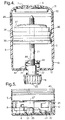
- a dispensing package (1) of the invention is made up of a body portion (3) having a cap (3) mounted thereon .
- the body portion (2) is defined by an oval shaped base wall (4) with a side wall (5) upstanding therefrom.
- the side wall (5) terminates in an opening (15) provided with a grill type top (6).
- the grill (6) defines openings (7) through which a cream can be dispensed.
- the body portion (2) is made up of three units namely a base portion (8) a central storage chamber (9) and a top portion (10).
- the base portion (8), the central storage chamber (9) and the top portion (10) are continuous to define the side wall (5) of the body.
- the side wall (5) of the body curves inwards towards the opening (15) to define an overhang (11) which is in mating relationship with the grill (6).
- the top portion (10) and the storage chamber (9) are also continuous with another to define the internal volume from which the composition is dispensed from the package.
- the overhang (11) ensures that fluid composition does not discharge from the container before mounting of the grill (6) in the opening (15). This is particularly advantageous during filling of the package with the composition when it is necessary to move the package along a production line.
- the base portion (8) is provided with a push button (12) which protrudes from the base portion (8).
- the button (12) is provided with an indent (13) to facilitate depression of the button (12) with a finger.
- the cap (3) is transparent so that the openings (7) of the grill (6) are visible.
- the cap (3) is dome-shaped and forms a tight fit with the top portion (10) of the body (2).
- the interior surface of the cap (3) is provided with stops (14) to maintain a head space between the cap (3) and the grill (6).
- FIG. 2 shows a perspective view of the central storage chamber (9) with the base portion (8) removed.
- the side wall (5) of the central storage chamber (9) is provided with a series of stepped ridges (16) which form a tight friction fit with the base portion (8).
- the central storage chamber (9) is provided with a bottom wall (17) to separate the central storage chamber (9) and the composition contained therein from the base portion (8).
- the side wall (5) of the central storage chamber (9) is upstanding from the bottom wall (17).
- the bottom wall (17) is provided with an orifice (41).
- a spindle (21) is inserted through the orifice (41) and is fixedly mounted on a rotatable cog (18) such that rotation of the cog (18) causes the spindle (21) to rotate.
- the rotatable cog (18) is provided with a side wall (24) moulded to define a peripheral toothed cam (19) oriented along the longitudinal axis of the spindle (21).
- the side wall (24) is provided with five ratchet teeth (20) oriented in a plane horizontal to the longitudinal axis of the spindle (21).
- the ratchet teeth (20) are disposed on the rim (23) of the side wall (24).
- a spring (22) is disposed between the cog (18) and the central storage chamber (9). The arrangement of the spring is more fully described with reference to Figure 4 below.
- Figure 3 shows a top plan view of the base portion (8) of the body (2).
- the base portion (8) is defined by the base wall (4) with the side wall (5) upstanding therefrom.
- the base portion (8) is provided with a centrally located circular fixed cam (25) having a diameter complimentary with the diameter of the rim (23) of the cog (18).
- the fixed cam (25) is mounted on the base wall (4) of the base portion (8).
- the fixed cam (25) is provided with a series of teeth (26) complimentary with and engageable with the ratchet teeth (20) of the rotatable cog (18).
- the button (12) is mounted in the side wall (5) of the base portion (8) and is displaceable into the base portion (8) through a button opening (35) provided in the side wall (5).
- the button (12) is resilient due to a button spring (27) attached to the interior of the base portion (8) by a button spring mounting (28).
- the button spring (27) enables the button (12) to be depressed.
- the button (12) is prevented from excessively entering the base portion (8) during depression by a button stop (29) fixed to the interior surface of the side wall (5).
- the button (12) is also provided with a pawl (30) oriented inwards towards the interior of the base chamber (8).
- the pawl (30) is engageable with the toothed cam (19) of the cog (18) as will be described more fully below.
- the base chamber (8) is further provided with a secondary series of walls (32) upstanding from the base wall (4).
- the secondary series of walls (32) defined secondary wells (31) for holding any composition which seeps through the orifice (41) into the base chamber (8).
- the fixed cam (25) is also provided with a tertiary series of walls arranged in spoke-like fashion upstanding from the base (4) of the base portion (8) to define a tertiary series of wells also to store any composition which seeps past the orifice (41).
- FIG 4 describes a longitudinal cross-sectional view through the central storage chamber (9).
- the central storage chamber (9) is provided with a bottom wall (17) and a side wall (5) upstanding therefrom as previously described.
- the spindle (21) mounted on the cog (18) is inserted through the orifice (41) into the central storage chamber (9).
- the bottom wall (17) is adapted to project inwards towards the interior of the central storage chamber (9) to define a bush (43) around the spindle (21).
- the bush (43) defines a smaller secondary orifice (44) through which the spindle (21) projects.
- the spring (22) is disposed between the cog (18) and the bush (43).
- the bush (43), the bottom wall (17) and the side wall (5) of the central storage chamber (9) together define a primary well (42) which also ensures minimal leakage of composition through the orifice (44).
- An elevator (36) is mounted on the spindle (21) and is displaceable between the bush (43) and the openings (7).
- the elevator (36) is in sliding relationship with the interior surface of the side wall (5).
- the elevator (36) is provided with a peripheral channel spaced from the interior surface of the side wall (5) to trap the composition to be dispensed and further prevent leakage past the elevator (36), a chamber sealing ring (38) situated below the peripheral channel (37) which forms a tight but sliding fit with the interior surface of the storage chamber (9) and a secondary sealing ring (39) also in a tight but sliding relationship with the interior surface of the side wall (5).
- the peripheral channel (37) and sealing rings (38) and (39) further enhance the resistance of the package of the invention to leakage of volatile and fluid materials.
- Figure 5 shows a cross-sectional view through the base chamber (8).
- the interior surface of the side wall (5) of the base chamber (8) is provided with a series of complimentary ridges (40) which form a friction tight fit with the ridges (16) of the central storage chamber (9) when the package is assembled as shown in Figure 1.
- FIG. 5 more clearly illustrates the arrangement of the push button (12) and the push button spring (27).
- the push button (12) is displaceable in the button opening (35) in the side wall (5) of the base chamber (8) while the fixed cam (25) is upstanding from the base wall (4) of the base chamber (8).
- the pawl (30) projects inwards from the push button (12) towards the fixed cam (25).
- the various components of the dispensing package (1) can be manufactured by utilising known moulding techniques.
- the package (1) is assembled by first assembling the central storage chamber (9), the spindle (21)/cog (18) and spring (22) without the top portion (10).
- the base portion (8) can then be engaged with the central storage chamber (9) by engaging the ridges (16) and (40) as previously described.
- the top portion (10) can then be fitted to the central storage chamber (9) in a frictional fit using ridges (45) on the top portion (10) and the central storage chamber (9) similar to the ridges (16,40) previously described.
- the opening (15) defined by the overhang (11) then remains.
- Composition to be stored within the storage chamber (9) can then be charged into the storage container (9) through the opening (15).
- a cream composition can be hot filled in the pack (1).
- Typical underarm cream compositions can have highly fluid properties when hot. Accordingly, the overhang (11) ensures that the composition is unlikely to accidentally discharge through the opening (15) during movement of the pack for instance along a production line.
- the grill (6) can then be snap fitted into the opening (15).
- Composition to be dispensed from the storage chamber (9) can exit through the openings (7) of the grill (6).
- the primary well (42), the secondary wells (31) and the tertiary wells (33) ensure that composition does not leak from the container over prolonged periods of time. Moreover, the tight fit formed by the various components of the pack (1) also ensure minimal leakage.
- the button (12) In use, to dispense composition from the storage chamber (9), the button (12) is depressed inwards.
- the pawl (30) therefore engages the toothed cams (19) to rotate the cog (18).
- the ratchet teeth (20) therefore ride over the complimentary teeth (26) of the fixed cam (25) in a reciprocating motion.
- the pawl (30) rotates the cog (18) and hence the spindle (21) to cause the elevator (36) to move upwards along the spindle (21) towards the openings (7) of the grill (6) thereby urging composition outwards through the openings (7).
- the ratchet teeth (20) ride up the ramped teeth (26) of the fixed cam (25) until the apex or crest of the teeth (26) is reached by the ratchet teeth (20). After reaching the apex of the teeth (26) the ratchet teeth (20) are urged downwards by the bias of screw (22) so that the cog (18)/spindle (21)/ elevator (36) retract to produce a suck back feature on the composition. Accordingly, no residual pressure remains on the composition following use.
- the volume of composition dispensed is determined by the number of times the button (12) is depressed or "clicked” by the user. Following dispensing of the required amount of composition the spring (22) always causes the cog to retract on the fixed cam (25) to relieve pressure on the composition.
- ratchet teeth (20), the teeth (26) and the spring (22) provide a suck back feature which prevents seepage or leaking of the composition (7) when not in use due to pressure relief.
- the package (1) can be held in the hand and the button (12) depressed with the thumb.
- the pack is suitable for use by left-handed or right-handed people.
- the composition can be massaged or rubbed into the skin surface while simultaneously clicking the button (12) to dispense composition through the openings (7).
- the package (1) facilitates rapid application of composition whilst at the same time minimising leakage of material through the pack.
- the pack (1) can be manufactured from a variety of suitable plastics materials.
- the body (2) can be manufactured from polypropylene, the piston from polyethylene and the button (12) form polyoxymethacrylate which provides a roughened finish which can prevent slippage in use.
- the spring (22) can be of stainless steel or a plastics material.
- the remaining components can also be manufactured from polypropylene.
Landscapes
- Containers And Packaging Bodies Having A Special Means To Remove Contents (AREA)
- Coating Apparatus (AREA)
- Closures For Containers (AREA)
Description
Claims (12)
- A dispensing package (1) for cream compositions comprising:such that, upon actuation of the button (12), the cog (18) and spindle (21) ride on the fixed cam (25) with a reciprocating motion which is transferred to the elevator (36) via the spindle (21).(a) a container body (2) having a longitudinal central axis;(b) the container body (2) defining a storage chamber for the composition;(c) an opening (15) in the container body (2) for discharging the composition;(d) a fixed cam (25) opposite said opening (15) having teeth (26) orientated tangentially to said longitudinal axis;(e) a rotatable cog (18) mounted on said cam (25) having a plurality of ratchet teeth (20) engageable with the teeth (26) of said fixed cam (25);(f) the cog (18) being provided with external peripheral cams (19) oriented parallel with said longitudinal axis;(g) an elevator (36) mounted on a spindle (21) and displaceable between the cog (18) and said opening (15) to dispense the composition through the opening (15);(h) a pawl (30) oriented transverse to the longitudinal axis and engageable with said peripheral cams (19) to rotate the cog (18) on the fixed cam;(i) an actuator button (12) attached to said pawl (30) to urge said pawl (30) against the peripheral cam (19);(j) a base (8) attached to the container body (2) in which the actuator button (12) is mounted by means of a button spring (27) and a button mounting (28), and having mounted therein the fixed cam (25); characterised in that(k) the spindle (21) is mounted on said cog (18) to rotate with said cog (18) and extends along said central longitudinal axis between the cog (18) and the opening (15)
- A dispensing package (1) as claimed in claim 1 characterised in that a spring (22) is mounted between the cog (18) and the elevator (36) to bias the cog (18) against the fixed cam (25).
- A dispensing package (1) as claimed in claim 1 or claim 2 characterised in that the actuator button (12) is off-set from the longitudinal axis of the container body (2) to enhance leverage about the spindle (21).
- A dispensing package (1) as claimed in any of claims 1 to 3 characterised in that the container body (2) has a first storage chamber (9) having a base wall, the storage chamber (9) housing the elevator (36) and spindle (21) and being mounted on and communicating with a base chamber (8) housing the fixed cam (25), the rotatable cog (18), the pawl (30) and the actuating button (12).
- A dispensing package (1) as claimed in claim 4 characterised in that the storage chamber (9) communicates with the base chamber (8) through an orifice defined by an upwardly extending skirt in the base wall (4) of the storage chamber (9), the upwardly extending skirt further defining a primary well in the storage chamber (9).
- A dispensing package (1) as claimed in claim 5 characterised in that the cog (18) is located below the base wall (4) and the spring (22) is mounted between the cog (18) and the base wall (4) such that the spring (22) does not contact the composition.
- A dispensing package (1) as claimed in claim 6 characterised in that the base chamber (8) is provided with a series of secondary wells defined by a plurality of upwardly extending walls in the base chamber (8) to receive any composition which escapes past the primary well.
- A dispensing package (1) as claimed in any of the preceding claims characterised in that the cog (18) is wheel shaped, the fixed cam (25) being complimentary in shape to the cog (18) so that the teeth (26) of the fixed cam (25) can engage the ratchet teeth (20) of the rotatable cog (18).
- A dispensing package (1) as claimed in claim 8 characterised in that the fixed cam (25) is defined by an upwardly extending circular wall provided with a plurality of internal walls (33) to define a tertiary series of internal wells for receiving composition.
- A dispensing package (1) as claimed in any of the preceding claims characterised in that the actuator button (12) is biased outwards from the pack by spring means (27) extending between the button (12) and the container body (2).
- A dispensing package (1) as claimed in any of the preceding claims characterised in that the opening (15) in the container body (2) for discharging the composition is defined by an inwardly curved portion of the container (2) body to define an overhang (11).
- A dispensing package as claimed in claim 11 characterised in that the opening (15) is substantially closed by a grill (6) through which the composition is dispensed.
Applications Claiming Priority (3)
| Application Number | Priority Date | Filing Date | Title |
|---|---|---|---|
| GB9521992 | 1995-10-27 | ||
| GBGB9521992.9A GB9521992D0 (en) | 1995-10-27 | 1995-10-27 | Dispensing package |
| PCT/EP1996/004171 WO1997016088A1 (en) | 1995-10-27 | 1996-09-20 | Dispensing package |
Publications (2)
| Publication Number | Publication Date |
|---|---|
| EP0858271A1 EP0858271A1 (en) | 1998-08-19 |
| EP0858271B1 true EP0858271B1 (en) | 2000-03-08 |
Family
ID=10782970
Family Applications (1)
| Application Number | Title | Priority Date | Filing Date |
|---|---|---|---|
| EP96933374A Expired - Lifetime EP0858271B1 (en) | 1995-10-27 | 1996-09-20 | Dispensing package |
Country Status (15)
| Country | Link |
|---|---|
| US (1) | US5839622A (en) |
| EP (1) | EP0858271B1 (en) |
| JP (1) | JPH11514535A (en) |
| CN (1) | CN1098661C (en) |
| AR (1) | AR004116A1 (en) |
| AU (1) | AU720962B2 (en) |
| BR (1) | BR9611185A (en) |
| CA (1) | CA2235374A1 (en) |
| DE (1) | DE69607023T2 (en) |
| ES (1) | ES2143229T3 (en) |
| GB (1) | GB9521992D0 (en) |
| PL (1) | PL182067B1 (en) |
| RU (1) | RU2201121C2 (en) |
| WO (1) | WO1997016088A1 (en) |
| ZA (1) | ZA968828B (en) |
Cited By (3)
| Publication number | Priority date | Publication date | Assignee | Title |
|---|---|---|---|---|
| WO2016061400A1 (en) * | 2014-10-15 | 2016-04-21 | Custom Rx Tda, Llc | Metering dispenser for flowable compositions |
| USD772066S1 (en) | 2015-06-03 | 2016-11-22 | Custom Rx Tda, Llc | Dispenser cover simulating a shell |
| US10086146B2 (en) | 2015-06-03 | 2018-10-02 | Doselogix, Llc | Flowable composition applicator |
Families Citing this family (52)
| Publication number | Priority date | Publication date | Assignee | Title |
|---|---|---|---|---|
| ATE253308T1 (en) * | 1997-05-13 | 2003-11-15 | Procter & Gamble | PACKAGED ANTISWEAT CREAM COMPOSITION |
| US6357945B1 (en) | 1998-01-21 | 2002-03-19 | Colgate Palmolive Company | Cosmetic dispenser |
| US5961007A (en) * | 1998-06-15 | 1999-10-05 | The Procter & Gamble Company | Dispensing package |
| US6042289A (en) * | 1998-10-01 | 2000-03-28 | Evans Enterprises | Device for dispensing particulate material |
| US6336763B1 (en) | 1998-10-07 | 2002-01-08 | Colgate-Palmolive Company | Applicator for flowable substances |
| DE19921662B4 (en) * | 1999-04-23 | 2004-08-12 | Henkel Kgaa | Cream and deodorant dispenser |
| AU746964B2 (en) | 1999-04-23 | 2002-05-09 | Henkel Kommanditgesellschaft Auf Aktien | Cream and deodorant dispenser |
| GB2354999B (en) * | 1999-10-08 | 2003-06-11 | Unilever Plc | Dispenser |
| WO2001087390A2 (en) | 2000-05-12 | 2001-11-22 | Iep Pharmaceutical Devices Inc. | Powder/liquid metering valve |
| USD435218S (en) * | 2000-07-05 | 2000-12-19 | Courtesy Corporation | Product dispenser top |
| US6269982B1 (en) * | 2000-07-06 | 2001-08-07 | Courtesy Corporation | Trigger activated product dispenser |
| US6398439B1 (en) | 2001-08-13 | 2002-06-04 | The Plastek Group | Oval rotary dispenser with pressure relief |
| US6450716B1 (en) | 2001-08-13 | 2002-09-17 | The Plastek Group | Round rotary dispenser with pressure relief |
| US6499900B1 (en) | 2001-10-16 | 2002-12-31 | Owens-Illinois Closure Inc. | Dual liquid dispensing packages |
| US20030164382A1 (en) * | 2002-02-27 | 2003-09-04 | Guy Thompson | Massage applicator for cosmetic compositions |
| US20030175376A1 (en) * | 2002-03-15 | 2003-09-18 | Robert Jahn | Extruding devices and methods thereof |
| US6739482B2 (en) * | 2002-04-23 | 2004-05-25 | Kevin M. Jaekel | Drywall compound dispensing device |
| US7467731B2 (en) * | 2003-01-14 | 2008-12-23 | Mickey Shraiber | Holder construction particularly useful for holding and dispensing pressure-flowable products, such as ice-cream or other relatively soft foods |
| US6918511B1 (en) * | 2003-06-17 | 2005-07-19 | Spatz Laboratories | Flow control product dispenser |
| US7074452B2 (en) * | 2003-06-21 | 2006-07-11 | Gary Lebowitz | Method and apparatus for individual frozen beverage mold and dispenser |
| US7309184B2 (en) * | 2003-08-15 | 2007-12-18 | Revlon Consumer Products Corporation | Dispenser for fluid materials |
| JP4468002B2 (en) * | 2004-02-02 | 2010-05-26 | 壽印刷紙工株式会社 | Side knock type feeding mechanism |
| US20050242126A1 (en) * | 2004-04-16 | 2005-11-03 | Izoe Jolly F | Dispenser for highly viscous liquids and pastes |
| DE602005024969D1 (en) * | 2004-07-02 | 2011-01-05 | Big Drum Iberica | DOSING CONTAINER FOR CREAMY ICE CREAM |
| CN100525673C (en) * | 2004-11-10 | 2009-08-12 | 株式会社资生堂 | Filler extruding container for coating |
| IL169636A (en) * | 2005-01-21 | 2008-11-03 | Mickey Shraiber | Holder construction particularly useful for holding and dispensing pressure-flowable products, such as ice-cream or other relatively soft foods |
| US7374360B1 (en) * | 2005-04-11 | 2008-05-20 | Plastek Industries, Inc. | Applicator for personal care compositions |
| US7213994B2 (en) * | 2005-07-01 | 2007-05-08 | Custom Rx Tda, Llc | Dosing dispenser for cream-based medicines |
| FR2889170B1 (en) * | 2005-07-26 | 2007-10-05 | Oreal | PACKAGING AND DISPENSING DEVICE |
| US8172472B2 (en) * | 2007-11-08 | 2012-05-08 | Tokiwa Corporation | Stick-shaped material extruding container |
| JP5177402B2 (en) * | 2008-02-04 | 2013-04-03 | ロート製薬株式会社 | Feeding container |
| EP2181691B1 (en) | 2008-10-27 | 2016-12-21 | Unilever PLC | Antiperspirant compositions |
| PL2181692T3 (en) | 2008-10-27 | 2017-04-28 | Unilever N.V. | Antiperspirant compositions |
| EP2221039B1 (en) | 2009-02-18 | 2017-11-22 | Unilever Plc, A Company Registered In England And Wales under company no. 41424 of Unilever House | Antiperspirant compositions |
| GB0910657D0 (en) | 2009-06-22 | 2009-08-05 | Unilever Plc | Antiperspirant compositions |
| CN102665483B (en) | 2009-09-16 | 2015-08-12 | 高露洁-棕榄公司 | Oral care systems, external member and method |
| KR101414966B1 (en) | 2009-12-23 | 2014-07-04 | 콜게이트-파아므올리브캄파니 | Oral care system, kit and method |
| EP2515699B1 (en) | 2009-12-23 | 2014-08-06 | Colgate-Palmolive Company | Oral care system |
| CN102665482B (en) | 2009-12-23 | 2015-06-17 | 高露洁-棕榄公司 | Oral care system |
| CA2780356C (en) | 2009-12-23 | 2015-02-03 | Colgate-Palmolive Company | Oral care system with detachable dispenser |
| KR200464645Y1 (en) * | 2010-12-09 | 2013-01-11 | (주)아모레퍼시픽 | Shake vessel |
| EP2810584A3 (en) | 2010-12-15 | 2015-02-25 | Colgate-Palmolive Company | Oral care dispenser and system using the same |
| US8544684B2 (en) | 2011-02-15 | 2013-10-01 | Ramiro M. Perez | Visual, bi-audible, and bi-tactile metered-dose transdermal medicament applicator |
| US10471242B2 (en) | 2011-02-15 | 2019-11-12 | Biosrx, Inc. | Applicator and system for administering and dispensing flowable pharmaceutical preparations |
| US8979408B2 (en) | 2012-06-26 | 2015-03-17 | Dead Down Wind, Llc | Method and apparatus for applying solid paint to skin |
| EP3244772B1 (en) | 2015-02-02 | 2023-07-26 | Colgate-Palmolive Company | Oral care material dispenser |
| US10028566B2 (en) * | 2016-01-08 | 2018-07-24 | Sam Houston State University | Personal hygiene assist device |
| US10625927B2 (en) | 2016-09-23 | 2020-04-21 | The Procter & Gamble Company | Consumer product package |
| US10315832B2 (en) | 2016-09-23 | 2019-06-11 | The Procter & Gamble Company | Consumer product package |
| USD890434S1 (en) | 2016-11-10 | 2020-07-14 | Steven Tyler BROWN | Hand-held fluid-substance applicator |
| US10435226B2 (en) | 2016-12-27 | 2019-10-08 | Doselogix, Llc | Dosing dispenser system |
| US11382400B2 (en) | 2018-08-10 | 2022-07-12 | Go Products Co. | Material applicator |
Family Cites Families (13)
| Publication number | Priority date | Publication date | Assignee | Title |
|---|---|---|---|---|
| US1663338A (en) * | 1926-05-06 | 1928-03-20 | Gagne Louis | Dispensing device |
| FR808754A (en) * | 1935-10-31 | 1937-02-15 | Dispensing device for creams or any other beauty products for presentation to the public | |
| CH261014A (en) * | 1944-10-17 | 1949-04-15 | Gabler Josef | Set of container parts which can be assembled to form a container for receiving and dispensing pasty substances. |
| CH281384A (en) * | 1949-08-20 | 1952-03-15 | Sandherr Ag M | Method for ejecting pastes from a container and device for carrying out this method. |
| CH508202A (en) * | 1969-02-26 | 1971-05-31 | Micromedic Systems Inc | Ratchet mechanism for driving a rotating member and use of this mechanism |
| GB8319991D0 (en) * | 1983-07-25 | 1983-08-24 | Unit Moulders Ltd | Dispenser for semifluid substances |
| US4595124A (en) * | 1985-03-29 | 1986-06-17 | The Gillette Company | Semi-solid cylindrical container and dispenser |
| US4753373A (en) * | 1986-04-15 | 1988-06-28 | Risdon Corporation | Positive displacement dispenser |
| US4767032A (en) * | 1986-09-02 | 1988-08-30 | L. Perrigo Company | Paste dispenser |
| ATE105680T1 (en) * | 1987-10-15 | 1994-06-15 | Procter & Gamble | ROTATING DISPENSER PACKAGING. |
| US4865231A (en) * | 1987-10-15 | 1989-09-12 | The Procter & Gamble Company | Button type dispensing package |
| US5000356A (en) * | 1987-10-15 | 1991-03-19 | The Procter & Gamble Company | Swivel-up type dispensing package |
| US5573341A (en) * | 1994-10-26 | 1996-11-12 | Chesebrough-Pond's Usa Co., Division Of Conopco, Inc. | Cosmetic composition dispenser |
-
1995
- 1995-10-27 GB GBGB9521992.9A patent/GB9521992D0/en active Pending
-
1996
- 1996-09-20 RU RU98109934/12A patent/RU2201121C2/en not_active IP Right Cessation
- 1996-09-20 PL PL96327240A patent/PL182067B1/en not_active IP Right Cessation
- 1996-09-20 ES ES96933374T patent/ES2143229T3/en not_active Expired - Lifetime
- 1996-09-20 JP JP9517014A patent/JPH11514535A/en not_active Ceased
- 1996-09-20 WO PCT/EP1996/004171 patent/WO1997016088A1/en active IP Right Grant
- 1996-09-20 BR BR9611185A patent/BR9611185A/en not_active IP Right Cessation
- 1996-09-20 CN CN96199430A patent/CN1098661C/en not_active Expired - Fee Related
- 1996-09-20 EP EP96933374A patent/EP0858271B1/en not_active Expired - Lifetime
- 1996-09-20 CA CA002235374A patent/CA2235374A1/en not_active Abandoned
- 1996-09-20 AU AU72137/96A patent/AU720962B2/en not_active Ceased
- 1996-09-20 DE DE69607023T patent/DE69607023T2/en not_active Expired - Fee Related
- 1996-09-26 US US08/720,280 patent/US5839622A/en not_active Expired - Fee Related
- 1996-10-21 ZA ZA9608828A patent/ZA968828B/en unknown
- 1996-10-25 AR ARP960104920A patent/AR004116A1/en unknown
Cited By (4)
| Publication number | Priority date | Publication date | Assignee | Title |
|---|---|---|---|---|
| WO2016061400A1 (en) * | 2014-10-15 | 2016-04-21 | Custom Rx Tda, Llc | Metering dispenser for flowable compositions |
| USD772066S1 (en) | 2015-06-03 | 2016-11-22 | Custom Rx Tda, Llc | Dispenser cover simulating a shell |
| USD823116S1 (en) | 2015-06-03 | 2018-07-17 | Doselogix, Llc | Dispenser cover simulating a shell |
| US10086146B2 (en) | 2015-06-03 | 2018-10-02 | Doselogix, Llc | Flowable composition applicator |
Also Published As
| Publication number | Publication date |
|---|---|
| ZA968828B (en) | 1998-04-21 |
| CN1206336A (en) | 1999-01-27 |
| WO1997016088A1 (en) | 1997-05-09 |
| ES2143229T3 (en) | 2000-05-01 |
| JPH11514535A (en) | 1999-12-14 |
| CA2235374A1 (en) | 1997-05-09 |
| BR9611185A (en) | 1999-05-11 |
| EP0858271A1 (en) | 1998-08-19 |
| RU2201121C2 (en) | 2003-03-27 |
| PL182067B1 (en) | 2001-10-31 |
| DE69607023D1 (en) | 2000-04-13 |
| GB9521992D0 (en) | 1996-01-03 |
| AU720962B2 (en) | 2000-06-15 |
| PL327240A1 (en) | 1998-12-07 |
| CN1098661C (en) | 2003-01-15 |
| AU7213796A (en) | 1997-05-22 |
| DE69607023T2 (en) | 2000-07-20 |
| US5839622A (en) | 1998-11-24 |
| AR004116A1 (en) | 1998-09-30 |
Similar Documents
| Publication | Publication Date | Title |
|---|---|---|
| EP0858271B1 (en) | Dispensing package | |
| US5879095A (en) | Dispenser for a product of liquid-to-pasty consistency, equipped with an application tip | |
| US4865231A (en) | Button type dispensing package | |
| US5000356A (en) | Swivel-up type dispensing package | |
| AU730050B2 (en) | Dose control dispenser | |
| CA1182431A (en) | Liquid dispensing pump arrangement with selective stroke restriction | |
| EP0709040B1 (en) | Cosmetic composition dispenser | |
| US10398211B2 (en) | Bottle cap with cosmetic kit | |
| US7600936B2 (en) | Dual dispenser pen | |
| CA2187641A1 (en) | Cosmetics container | |
| US20050036823A1 (en) | Dispenser for fluid materials | |
| AU623350B2 (en) | Swivel-up type dispensing package | |
| CA2005616C (en) | Liquid dispenser | |
| US4848595A (en) | Product dispenser with shiftable closure blade | |
| WO1991019573A1 (en) | Nail fluid bottle cover | |
| US9775424B2 (en) | Applicator having a lid usable as a handle | |
| AU2005263450B2 (en) | Cosmetic dispenser housing and method | |
| NO155831B (en) | Roll-on dispenser. | |
| KR20180127977A (en) | Compressible dispensers for liquid products, especially cosmetic liquid products such as creams | |
| JPS63234910A (en) | Bottle for delivering product | |
| WO2006012350A2 (en) | Package including an overcap having an integral compartment for a secondary product | |
| US20040163663A1 (en) | Lipstick breath freshener dispensers | |
| CA1066157A (en) | Rechargeable applicator for dispensing substances | |
| KR20150088553A (en) | Palette type liquid makeup case | |
| GB2099764A (en) | Method and device or removing body hair |
Legal Events
| Date | Code | Title | Description |
|---|---|---|---|
| PUAI | Public reference made under article 153(3) epc to a published international application that has entered the european phase |
Free format text: ORIGINAL CODE: 0009012 |
|
| 17P | Request for examination filed |
Effective date: 19980409 |
|
| AK | Designated contracting states |
Kind code of ref document: A1 Designated state(s): DE ES FR GB IT SE |
|
| GRAG | Despatch of communication of intention to grant |
Free format text: ORIGINAL CODE: EPIDOS AGRA |
|
| 17Q | First examination report despatched |
Effective date: 19990511 |
|
| GRAG | Despatch of communication of intention to grant |
Free format text: ORIGINAL CODE: EPIDOS AGRA |
|
| GRAH | Despatch of communication of intention to grant a patent |
Free format text: ORIGINAL CODE: EPIDOS IGRA |
|
| GRAH | Despatch of communication of intention to grant a patent |
Free format text: ORIGINAL CODE: EPIDOS IGRA |
|
| GRAA | (expected) grant |
Free format text: ORIGINAL CODE: 0009210 |
|
| AK | Designated contracting states |
Kind code of ref document: B1 Designated state(s): DE ES FR GB IT SE |
|
| REF | Corresponds to: |
Ref document number: 69607023 Country of ref document: DE Date of ref document: 20000413 |
|
| ET | Fr: translation filed | ||
| REG | Reference to a national code |
Ref country code: ES Ref legal event code: FG2A Ref document number: 2143229 Country of ref document: ES Kind code of ref document: T3 |
|
| ITF | It: translation for a ep patent filed | ||
| PLBE | No opposition filed within time limit |
Free format text: ORIGINAL CODE: 0009261 |
|
| STAA | Information on the status of an ep patent application or granted ep patent |
Free format text: STATUS: NO OPPOSITION FILED WITHIN TIME LIMIT |
|
| 26N | No opposition filed | ||
| REG | Reference to a national code |
Ref country code: GB Ref legal event code: IF02 |
|
| PGFP | Annual fee paid to national office [announced via postgrant information from national office to epo] |
Ref country code: GB Payment date: 20050914 Year of fee payment: 10 |
|
| PGFP | Annual fee paid to national office [announced via postgrant information from national office to epo] |
Ref country code: FR Payment date: 20050919 Year of fee payment: 10 |
|
| PGFP | Annual fee paid to national office [announced via postgrant information from national office to epo] |
Ref country code: SE Payment date: 20050921 Year of fee payment: 10 |
|
| PGFP | Annual fee paid to national office [announced via postgrant information from national office to epo] |
Ref country code: ES Payment date: 20050927 Year of fee payment: 10 |
|
| PGFP | Annual fee paid to national office [announced via postgrant information from national office to epo] |
Ref country code: DE Payment date: 20051031 Year of fee payment: 10 |
|
| PG25 | Lapsed in a contracting state [announced via postgrant information from national office to epo] |
Ref country code: SE Free format text: LAPSE BECAUSE OF NON-PAYMENT OF DUE FEES Effective date: 20060921 |
|
| PGFP | Annual fee paid to national office [announced via postgrant information from national office to epo] |
Ref country code: IT Payment date: 20060930 Year of fee payment: 11 |
|
| PG25 | Lapsed in a contracting state [announced via postgrant information from national office to epo] |
Ref country code: DE Free format text: LAPSE BECAUSE OF NON-PAYMENT OF DUE FEES Effective date: 20070403 |
|
| EUG | Se: european patent has lapsed | ||
| GBPC | Gb: european patent ceased through non-payment of renewal fee |
Effective date: 20060920 |
|
| REG | Reference to a national code |
Ref country code: FR Ref legal event code: ST Effective date: 20070531 |
|
| PG25 | Lapsed in a contracting state [announced via postgrant information from national office to epo] |
Ref country code: GB Free format text: LAPSE BECAUSE OF NON-PAYMENT OF DUE FEES Effective date: 20060920 |
|
| REG | Reference to a national code |
Ref country code: ES Ref legal event code: FD2A Effective date: 20060921 |
|
| PG25 | Lapsed in a contracting state [announced via postgrant information from national office to epo] |
Ref country code: ES Free format text: LAPSE BECAUSE OF NON-PAYMENT OF DUE FEES Effective date: 20060921 |
|
| PG25 | Lapsed in a contracting state [announced via postgrant information from national office to epo] |
Ref country code: FR Free format text: LAPSE BECAUSE OF NON-PAYMENT OF DUE FEES Effective date: 20061002 |
|
| PG25 | Lapsed in a contracting state [announced via postgrant information from national office to epo] |
Ref country code: IT Free format text: LAPSE BECAUSE OF NON-PAYMENT OF DUE FEES Effective date: 20070920 |