EP0857407B1 - Bodenbearbeitungsvorrichtung - Google Patents
Bodenbearbeitungsvorrichtung Download PDFInfo
- Publication number
- EP0857407B1 EP0857407B1 EP98200124A EP98200124A EP0857407B1 EP 0857407 B1 EP0857407 B1 EP 0857407B1 EP 98200124 A EP98200124 A EP 98200124A EP 98200124 A EP98200124 A EP 98200124A EP 0857407 B1 EP0857407 B1 EP 0857407B1
- Authority
- EP
- European Patent Office
- Prior art keywords
- working
- soil
- frame
- outriggers
- axis
- Prior art date
- Legal status (The legal status is an assumption and is not a legal conclusion. Google has not performed a legal analysis and makes no representation as to the accuracy of the status listed.)
- Expired - Lifetime
Links
Images


Classifications
-
- A—HUMAN NECESSITIES
- A01—AGRICULTURE; FORESTRY; ANIMAL HUSBANDRY; HUNTING; TRAPPING; FISHING
- A01B—SOIL WORKING IN AGRICULTURE OR FORESTRY; PARTS, DETAILS, OR ACCESSORIES OF AGRICULTURAL MACHINES OR IMPLEMENTS, IN GENERAL
- A01B17/00—Ploughs with special additional arrangements, e.g. means for putting manure under the soil, clod-crushers ; Means for breaking the subsoil
- A01B17/004—Clod-crushers
Definitions
- the invention relates to a device for working soil, comprising a frame which is provided with means for coupling thereof to a tractor or other agricultural machine and in which is accommodated at least one working body which is rotatable on a lying axis, the coupling means comprising at least two substantially parallel outriggers that are adjustable in their length direction, the coupling means being arranged such that during use the axis encloses an angle to the direction of movement of the tractor or agricultural machine.
- a device which is particularly suitable for pulverizing larger pieces of mutually affixed soil, such as for instance plough cuts created after a soil working with an agricultural plough, is known from AT-B-374 073. This pulverizing is important to improve the structure of the soil after ploughing, with a view to sowing or planting new crops in the spring.
- This prior art document AT-B-374 073 discloses a post-treatment device for a plough which is suitable for pulverizing plough cuts formed by the plough.
- This post-treatment device is formed by an auxiliary frame suspended from the plough by a number of parallel length-adjustable outriggers.
- the frame which has a rotatable shaft journalled therein, running parallel to the boom of the plough.
- the shaft is thus placed at an acute angle to the travel direction. Pairs of elongated teeth extend perpendicularly from the shaft at regular intervals for pulverizing the ground.
- the outriggers are pivotable about horizontal axes for adjusting the working depth of the rotatable shaft and teeth.
- the shaft is arranged on carriages that are slidable in vertical direction in order to adjust the working depth of the teeth.
- the invention now has for its object to provide an improved device of the above described type.
- this is achieved in that the outriggers are adapted to receive the frame such that it is slidable in its length direction to allow adjustment the position of the or each working body.
- the working device can be made suitable in simple manner for working many diverse types of soil.
- the width of the device can moreover be changed by changing the position of the or each working body, which is important inter alia when the agricultural machine is revolved on its axis at the end of a field or for transport by road of the soil working device.
- the device can be coupled directly to an agricultural tractor and thus used separately, but can also be employed in combination with for instance an agricultural plough coupled to a tractor, so that in a single working operation the soil can be ploughed and further pulverized.
- the coupling means comprise clamping sleeves with which the frame can be fixed in different positions.
- the outriggers are pivotable on standing shafts and the coupling means are further provided with means for adjusting the pivot angle of the outriggers.
- These pivot angle adjusting means can be operated hydraulically so that the device can be adjusted with little effort.
- the or each working body may be elongate and may have a periphery which extends substantially parallel to the rotation axis and on which a number of protruding working members are arranged with interspacing.
- the working body can thus form a roller which is provided with protrusions.
- At least a part of the working members advantageously encloses an angle herein with a radial from the axis of rotation and thus, in other words, does not lie perpendicularly of the working body.
- the working members can comprise knives which are advantageously placed substantially parallel to the rotation axis of the or each working body. These knives can herein advantageously be arranged in a spiral-shaped line on the or each working body and are preferably detachable in order to enable their removal for servicing or replacement.
- the device may comprise a number of working bodies in the form of mutually parallel, separately rotatable discs. By causing such discs to rotate at an angle relative to the working direction a very good pulverizing working of the soil is obtained.
- the discs When on the other hand the discs are each connected to the frame for pivoting on a standing shaft, they can follow the direction of movement of the device and serve to press down the worked soil.
- the device can also have means for rotatable driving of the or each working body, for instance in the form of a hydraulic motor or a mechanical transmission connected to the power take-off of an agricultural tractor.
- the invention also relates to an assembly of an agricultural machine, such as a plough, and one or more soil working devices as described above coupled thereto. With such an assembly two or more operations can be performed in one working cycle, thus achieving a great time-saving, while moreover a field does not have to be travelled over unnecessarily, this ultimately enhancing the soil structure.
- the soil working device is herein advantageously coupled at least partially to the side of the agricultural machine, as seen in the direction of movement, so that ploughed-up earth, so-called plough-soil, which is thrown out to one side, can be immediately pulverized.
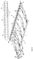
- An assembly 2 according to the invention moved forward by a tractor 1 consists of an agricultural plough 3 and a soil working device 4 coupled adjacently of or at an angle behind the plough (fig. 1).
- Plough 3 comprises in the usual manner a frame or boom 5 to which is fixed a number of ploughshares 6 with which plough cuts 14 are formed in soil 13.
- Fixed to frame 5 are two outriggers 7 in which two arms 8 are received.
- Outriggers 7 and arms 8 received therein form the coupling means 16 of the soil working device 4.
- Outriggers 7 are pivotable on lying shafts 21 so that the working depth of device 4 can be adjusted. Adjustment of the working depth can take place manually as well as by mechanical or hydraulic means. Use can be made in the depth adjustment by mechanical means of an adjustable stop.
- the soil working device 4 comprises a frame 9 in which in the shown embodiment, a single working body 10 is arranged which is rotatably mounted with both its ends in bearings 11.
- the bearings 11 herein define a lying or horizontal axis of rotation A which encloses an angle ⁇ with the working direction or the travel direction D of tractor 1.
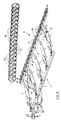
- Arranged on working body 10 is a large number of protruding, separate working members 12 which in the shown embodiment are placed in two spiral-shaped lines round working body 10.
- the working members 12 do not herein extend in accordance with a radial of working body 10 but enclose an angle therewith and are therefore, in other words, arranged sloping to the rear relative to working body 10.
- the working members 12 are hereby self-discharging, i.e.
- the working members 12 herein take the form of knives placed with their cutting edge parallel to the axis of rotation A. It is of course also possible to place the knives 12 with their cutting edge at an angle relative to the axis of rotation, depending on the soil type to be worked. Knives 12 can otherwise be arranged releasably on working body 10 so that in the case of wear they can be detached in simple manner, for instance for sharpening or even for replacement.
- the coupling means 16 connecting frame 9 to plough 3 are adapted to adjust the position of working body 10.
- the coupling means comprise for this purpose a pin-hole system 15 with which the arms 8 of frame 9, which are received slidably according to arrow B in the outriggers 7 connected to the plough frame 5, can be fixed in different slide-out lengths.
- the coupling means 16 comprise a pair of clamping sleeves 17 with which the frame 9, which is slidable in the direction of arrow L, can be fixed in different positions.
- the soil working device 4 is provided with a number of mutually parallel working bodies in the form of discs 19 which are each rotatable on a rotation axis 20.
- the discs 19 are herein each accommodated in a forked outrigger 18 which is fixed at an angle ⁇ to frame 9.
- a singly embodied outrigger can of course also be used.
- the angle at which discs 19 are pulled through the soil 13 is thus equal to the angle difference ⁇ - ⁇ .
- the action of the discs 19 can be adapted to the soil type being worked by device 4.
- pivot angle adjusting means 24 can take the form of a single beam 25 with openings 26 which co-act with a pin (not shown here) which is connected to frame 5 of plough 3 (fig. 5), but can also be formed by a hydraulic cylinder 27 which is connected to plough frame 5 and of which the piston rod 28 is connected to one of the outriggers 7 (fig. 4).
- the frame 9 By adjusting the pivot angle of outriggers 7 the frame 9 can be displaced forward or rearward in the travel direction relative to the plough frame 5, wherein the distance transversely of the working direction between plough frame 5 and frame 9 also increases or decreases. Thus can be ensured that working body 10 follows the plough cuts in all conditions.
- the working device 4 can in this manner also be folded toward the plough frame 5 when for instance the plough has to be turned on its longitudinal axis at the end of a field or when the plough with the working device 4 has to be transported by road.
- the device 4 is described above with reference to embodiments with which the soil can be pulverized, it is also possible to use the device 4 to press down the worked soil.
- the working bodies can be embodied as mutually parallel, separately rotatable discs 19 which, in contrast to the embodiments of fig. 3 and 5, are then not fixed rigidly to frame 9 but are pivotable relative thereto round a standing shaft 28.
- Making the discs 19 freely pivotable relative to frame 9 ensures that they will align themselves in the direction of forward movement of plough 3 and device 4 over the ground, whereby they will not so much reduce the soil as press it down.
- the specific form of the discs 19 can vary therein depending on the nature of the soil for working. Discs 19 can thus be convex and closed (fig. 6), while for other soil types flat, open discs in the form of spoked wheels 29 (fig. 7 and 8) may be more suitable.
- the soil working device 4 can otherwise also be provided with drive means, whereby the working body 10 can be rotated.
- a good working is also possible of for instance a very heavy soil, such as a moist clay soil, in which the working body 10 or the working bodies 19 would perhaps rotate insufficiently.
Landscapes
- Life Sciences & Earth Sciences (AREA)
- Soil Working Implements (AREA)
- Engineering & Computer Science (AREA)
- Mechanical Engineering (AREA)
- Soil Sciences (AREA)
- Environmental Sciences (AREA)
- Vehicle Body Suspensions (AREA)
Claims (10)
- Vorrichtung (4) zur Bodenbearbeitung, aufweisend einen Rahmen (9), welcher mit Mitteln (16) zu seinem Ankuppeln an einen Traktor (1) oder an eine andere Landwirtschaftsmaschine (3) versehen ist und in welchem zumindest ein Arbeitskörper (10, 19) untergebracht ist, welcher um eine liegende Achse (A, 20) drehbar ist, wobei die Kuppelmittel (16) zumindest zwei im Wesentlichen parallele Träger (7) aufweisen, die in ihrer Längsrichtung einstellbar sind, wobei die Kuppelmittel (16) so angeordnet sind, dass während der Verwendung die Achse (A, 20) einen Winkel (α, β-α) zur Bewegungsrichtung (D) des Traktors (1) oder der Landwirtschaftsmaschine (3) einschließt, dadurch gekennzeichnet, dass die Träger (7) angepasst sind, um den Rahmen (9) so aufzunehmen, dass er in seiner Längsrichtung verschiebbar ist, um ein Einstellen der Position des oder jedes Arbeitskörpers (10, 19) zu ermöglichen.
- Bodenbearbeitungsvorrichtung (4) gemäß Anspruch 1, dadurch gekennzeichnet, dass die Kuppelmittel (16) Klemmmanschetten (17) aufweisen, mit denen der Rahmen (9) in verschiedenen Positionen fixiert werden kann.
- Vorrichtung (4) zur Bodenbearbeitung, aufweisend einen Rahmen (9), welcher mit Mitteln (16) zum Kuppeln desselben mit einem Traktor (1) oder einer anderen Landwirtschaftsmaschine (3) versehen ist, und in welchem zumindest ein Arbeitskörper (10, 19) untergebracht ist, welcher um eine liegende Achse (A, 20) drehbar ist, wobei die Kuppelmittel (16) zumindest zwei im Wesentlichen parallele Träger (7) aufweisen, die in ihrer Längsrichtung einstellbar sind, wobei die Kuppelmittel (16) so angeordnet sind, dass während der Verwendung die Achse (A, 20) einen Winkel (α, β-α) zur Bewegungsrichtung (D) des Traktors (1) oder der Landwirtschaftsmaschine (3) einschließt, dadurch gekennzeichnet, dass die Träger (7) um stehende Achsen (23) schwenkbar sind, um eine Einstellung der Position des oder jedes Arbeitskörpers (10, 19) zu ermöglichen, und das die Kuppelmittel (16) ferner mit Mitteln (24) zum Einstellen des Schwenkwinkels der Träger (7) versehen sind.
- Bodenbearbeitungsvorrichtung (4) gemäß Anspruch 4, dadurch gekennzeichnet, dass die Schwenkwinkeleinstellmittel (24) hydraulisch betätigt werden können.
- Bodenbearbeitungsvorrichtung (4) gemäß einem der vorhergehenden Ansprüche, dadurch gekennzeichnet, dass der oder jeder Arbeitskörper (10) länglich ist und einen Umfang aufweist, welcher sich im Wesentlichen parallel zur Rotationsachse (A) erstreckt und an welchem eine Anzahl hervorstehender Arbeitsteile (12) mit Zwischenraum angeordnet sind.
- Bodenbearbeitungsvorrichtung (4) gemäß einem der vorhergehenden Ansprüche, dadurch gekennzeichnet, dass zumindest ein Teil der Arbeitsteile (12) einen Winkel mit einer Radialen der Rotationsachse (A) einschließt.
- Bodenbearbeitungsvorrichtung (4) gemäß einem der vorhergehenden Ansprüche, dadurch gekennzeichnet, dass die Arbeitsteile (12) Messer aufweisen, die im Wesentlichen parallel zur Rotationsachse (A) des oder jedes Arbeitskörpers (10) positioniert sind und daran in einer schraubenförmigen Linie angeordnet sind.
- Bodenbearbeitungsvorrichtung (4) gemäß einem der vorhergehenden Ansprüche, gekennzeichnet durch eine Anzahl von Arbeitskörpern in der Form von zueinander parallelen, separat drehbaren Scheiben (19, 29).
- Bodenbearbeitungsvorrichtung (4) gemäß Anspruch 8, dadurch gekennzeichnet, dass jede der Scheiben (19, 29) mit dem Rahmen (9) gekuppelt ist zum Schwenken um eine feststehende Achse (28).
- Gefüge (2) einer Landwirtschaftsmaschine (3), wie ein Pflug, und eine oder mehr Erdbearbeitungsvorrichtungen (4) gemäß einem der vorhergehenden Ansprüche.
Applications Claiming Priority (4)
| Application Number | Priority Date | Filing Date | Title |
|---|---|---|---|
| NL1005034 | 1997-01-17 | ||
| NL1005034 | 1997-01-17 | ||
| NL1005716A NL1005716C2 (nl) | 1997-01-17 | 1997-04-03 | Inrichting voor het bewerken van de bodem. |
| NL1005716 | 1997-04-03 |
Publications (2)
| Publication Number | Publication Date |
|---|---|
| EP0857407A1 EP0857407A1 (de) | 1998-08-12 |
| EP0857407B1 true EP0857407B1 (de) | 2002-06-12 |
Family
ID=26642516
Family Applications (1)
| Application Number | Title | Priority Date | Filing Date |
|---|---|---|---|
| EP98200124A Expired - Lifetime EP0857407B1 (de) | 1997-01-17 | 1998-01-19 | Bodenbearbeitungsvorrichtung |
Country Status (5)
| Country | Link |
|---|---|
| EP (1) | EP0857407B1 (de) |
| AT (1) | ATE218793T1 (de) |
| DE (1) | DE69805872T2 (de) |
| DK (1) | DK0857407T3 (de) |
| NL (1) | NL1005716C2 (de) |
Cited By (1)
| Publication number | Priority date | Publication date | Assignee | Title |
|---|---|---|---|---|
| DE102011122537A1 (de) | 2011-12-21 | 2013-06-27 | Lemken Gmbh & Co. Kg | Integriertes Bodenbearbeitungsgerät für Drehpflüge |
Families Citing this family (1)
| Publication number | Priority date | Publication date | Assignee | Title |
|---|---|---|---|---|
| CN104488384B (zh) * | 2014-12-31 | 2016-05-18 | 中联重机股份有限公司 | 一种铧式复合犁及拖拉机 |
Family Cites Families (11)
| Publication number | Priority date | Publication date | Assignee | Title |
|---|---|---|---|---|
| DE198326C (de) * | ||||
| GB922353A (en) * | 1960-09-20 | 1963-03-27 | Harold Douglas Ponton | Improvements in or relating to soil-working implements |
| US3233684A (en) * | 1961-12-13 | 1966-02-08 | Phillips Noah Oliver | Cultivating apparatus |
| US3162248A (en) * | 1962-04-28 | 1964-12-22 | Hoknnoki Company Ltd | Mold board type plough |
| DE1632787A1 (de) * | 1968-02-29 | 1971-01-07 | Rabewerk Clausing Heinrich | Kombination von Bodenbearbeitungsgeraeten |
| GB1249243A (en) * | 1969-09-18 | 1971-10-13 | Nat Res Dev | Improvements in or relating to agricultural implements |
| AT374073B (de) * | 1981-11-27 | 1984-03-12 | Sommer Leopold | Nachbearbeitungsgeraet fuer pfluege |
| JPS60116802U (ja) * | 1984-01-17 | 1985-08-07 | スタ−農機株式会社 | 耕耘砕土機 |
| DE3540158A1 (de) * | 1985-11-13 | 1987-05-14 | Franz Krampe | Mehrschariger pflug |
| DE3712540A1 (de) * | 1987-04-13 | 1988-11-03 | Bayerische Pflugfabrik Gmbh | Pflugnachlaeufer |
| FR2668023B1 (fr) * | 1990-10-22 | 1993-01-15 | Kuhn Sa | Machine agricole de travail du sol comportant un rotor qui s'etend obliquement par rapport a la direction d'avance au travail. |
-
1997
- 1997-04-03 NL NL1005716A patent/NL1005716C2/nl not_active IP Right Cessation
-
1998
- 1998-01-19 DK DK98200124T patent/DK0857407T3/da active
- 1998-01-19 EP EP98200124A patent/EP0857407B1/de not_active Expired - Lifetime
- 1998-01-19 AT AT98200124T patent/ATE218793T1/de active
- 1998-01-19 DE DE69805872T patent/DE69805872T2/de not_active Expired - Lifetime
Cited By (4)
| Publication number | Priority date | Publication date | Assignee | Title |
|---|---|---|---|---|
| DE102011122537A1 (de) | 2011-12-21 | 2013-06-27 | Lemken Gmbh & Co. Kg | Integriertes Bodenbearbeitungsgerät für Drehpflüge |
| WO2013091608A2 (de) | 2011-12-21 | 2013-06-27 | Lemken Gmbh & Co. Kg | Integriertes bodenbearbeitungsgerät für drehpflüge |
| WO2013091608A3 (de) * | 2011-12-21 | 2013-08-29 | Lemken Gmbh & Co. Kg | Integriertes bodenbearbeitungsgerät für drehpflüge |
| DE102011122537B4 (de) | 2011-12-21 | 2017-03-30 | Lemken Gmbh & Co. Kg | Integriertes Bodenbearbeitungsgerät für Drehpflüge |
Also Published As
| Publication number | Publication date |
|---|---|
| DK0857407T3 (da) | 2002-09-23 |
| EP0857407A1 (de) | 1998-08-12 |
| ATE218793T1 (de) | 2002-06-15 |
| DE69805872T2 (de) | 2002-11-28 |
| NL1005716C2 (nl) | 1998-07-20 |
| DE69805872D1 (de) | 2002-07-18 |
Similar Documents
| Publication | Publication Date | Title |
|---|---|---|
| US2974469A (en) | Mower with extensible mounting frame and power transmitting means | |
| US5535832A (en) | Land leveler and cultivator | |
| EP1088477A2 (de) | Landmaschine und Verfahren zum Falten von zwei Balken einer Landmaschine | |
| US4564073A (en) | Plow or harrow | |
| US3508617A (en) | Agricultural soil treating implements | |
| US3952810A (en) | Slit trenching and cable laying device | |
| WO1999002027A1 (en) | Tillage implement with on-the-go angle and depth controlled discs | |
| US4371039A (en) | Tool bar control for agricultural implement | |
| US2845014A (en) | Two-way plow with universal tool head | |
| EP0857407B1 (de) | Bodenbearbeitungsvorrichtung | |
| NL8204705A (nl) | Grondbewerkingsrol. | |
| US4699219A (en) | Cultivator drag bar and mounting therefor | |
| WO1997040660A1 (en) | Agricultural machine | |
| CN210183813U (zh) | 一种翻土方向可调的四圆盘犁 | |
| EP2820931B1 (de) | Bodenbearbeitungsmaschine mit einer verbesserten Vorrichtung zum Einstellen der Arbeitstiefe | |
| GB2127662A (en) | A soil cultivating machine | |
| US4206812A (en) | Rotary rock windrower | |
| GB2147481A (en) | Soil cultivating implements | |
| US3130796A (en) | Earth conditioning implement | |
| CN217406965U (zh) | 一种土地整理机械装置 | |
| GB2147183A (en) | Agricultural equipment | |
| EP0031621B1 (de) | Pflüge | |
| US3371721A (en) | Rotary spade plow | |
| EP0470026B1 (de) | Mehrzweckscheibenpflug | |
| EP1747707B1 (de) | Bodenbearbeitungsgerät (Rotorzylinder-Pflug) für das Wenden von Erdreich |
Legal Events
| Date | Code | Title | Description |
|---|---|---|---|
| PUAI | Public reference made under article 153(3) epc to a published international application that has entered the european phase |
Free format text: ORIGINAL CODE: 0009012 |
|
| AK | Designated contracting states |
Kind code of ref document: A1 Designated state(s): AT BE DE DK FR GB IE NL |
|
| AX | Request for extension of the european patent |
Free format text: AL;LT;LV;MK;RO;SI |
|
| 17P | Request for examination filed |
Effective date: 19990113 |
|
| AKX | Designation fees paid |
Free format text: AT BE DE DK FR GB IE NL |
|
| RBV | Designated contracting states (corrected) |
Designated state(s): AT BE DE DK FR GB IE NL |
|
| 17Q | First examination report despatched |
Effective date: 19990928 |
|
| GRAG | Despatch of communication of intention to grant |
Free format text: ORIGINAL CODE: EPIDOS AGRA |
|
| GRAG | Despatch of communication of intention to grant |
Free format text: ORIGINAL CODE: EPIDOS AGRA |
|
| GRAH | Despatch of communication of intention to grant a patent |
Free format text: ORIGINAL CODE: EPIDOS IGRA |
|
| GRAH | Despatch of communication of intention to grant a patent |
Free format text: ORIGINAL CODE: EPIDOS IGRA |
|
| GRAA | (expected) grant |
Free format text: ORIGINAL CODE: 0009210 |
|
| AK | Designated contracting states |
Kind code of ref document: B1 Designated state(s): AT BE DE DK FR GB IE NL |
|
| REF | Corresponds to: |
Ref document number: 218793 Country of ref document: AT Date of ref document: 20020615 Kind code of ref document: T |
|
| REG | Reference to a national code |
Ref country code: GB Ref legal event code: FG4D |
|
| REF | Corresponds to: |
Ref document number: 69805872 Country of ref document: DE Date of ref document: 20020718 |
|
| REG | Reference to a national code |
Ref country code: IE Ref legal event code: FG4D |
|
| REG | Reference to a national code |
Ref country code: DK Ref legal event code: T3 |
|
| ET | Fr: translation filed | ||
| PLBE | No opposition filed within time limit |
Free format text: ORIGINAL CODE: 0009261 |
|
| STAA | Information on the status of an ep patent application or granted ep patent |
Free format text: STATUS: NO OPPOSITION FILED WITHIN TIME LIMIT |
|
| 26N | No opposition filed |
Effective date: 20030313 |
|
| PGFP | Annual fee paid to national office [announced via postgrant information from national office to epo] |
Ref country code: IE Payment date: 20111230 Year of fee payment: 15 |
|
| PGFP | Annual fee paid to national office [announced via postgrant information from national office to epo] |
Ref country code: DK Payment date: 20120430 Year of fee payment: 15 |
|
| PGFP | Annual fee paid to national office [announced via postgrant information from national office to epo] |
Ref country code: GB Payment date: 20120425 Year of fee payment: 15 Ref country code: FR Payment date: 20120529 Year of fee payment: 15 |
|
| PGFP | Annual fee paid to national office [announced via postgrant information from national office to epo] |
Ref country code: AT Payment date: 20120427 Year of fee payment: 15 |
|
| REG | Reference to a national code |
Ref country code: DK Ref legal event code: EBP |
|
| REG | Reference to a national code |
Ref country code: AT Ref legal event code: MM01 Ref document number: 218793 Country of ref document: AT Kind code of ref document: T Effective date: 20130131 |
|
| GBPC | Gb: european patent ceased through non-payment of renewal fee |
Effective date: 20130119 |
|
| REG | Reference to a national code |
Ref country code: IE Ref legal event code: MM4A |
|
| REG | Reference to a national code |
Ref country code: FR Ref legal event code: ST Effective date: 20130930 |
|
| PG25 | Lapsed in a contracting state [announced via postgrant information from national office to epo] |
Ref country code: AT Free format text: LAPSE BECAUSE OF NON-PAYMENT OF DUE FEES Effective date: 20130131 |
|
| PG25 | Lapsed in a contracting state [announced via postgrant information from national office to epo] |
Ref country code: GB Free format text: LAPSE BECAUSE OF NON-PAYMENT OF DUE FEES Effective date: 20130119 Ref country code: FR Free format text: LAPSE BECAUSE OF NON-PAYMENT OF DUE FEES Effective date: 20130131 |
|
| PG25 | Lapsed in a contracting state [announced via postgrant information from national office to epo] |
Ref country code: DK Free format text: LAPSE BECAUSE OF NON-PAYMENT OF DUE FEES Effective date: 20130131 Ref country code: IE Free format text: LAPSE BECAUSE OF NON-PAYMENT OF DUE FEES Effective date: 20130119 |
|
| PGFP | Annual fee paid to national office [announced via postgrant information from national office to epo] |
Ref country code: NL Payment date: 20140731 Year of fee payment: 17 Ref country code: DE Payment date: 20140731 Year of fee payment: 17 |
|
| PGFP | Annual fee paid to national office [announced via postgrant information from national office to epo] |
Ref country code: BE Payment date: 20140728 Year of fee payment: 17 |
|
| PG25 | Lapsed in a contracting state [announced via postgrant information from national office to epo] |
Ref country code: BE Free format text: LAPSE BECAUSE OF NON-PAYMENT OF DUE FEES Effective date: 20150131 |
|
| REG | Reference to a national code |
Ref country code: DE Ref legal event code: R119 Ref document number: 69805872 Country of ref document: DE |
|
| REG | Reference to a national code |
Ref country code: NL Ref legal event code: V1 Effective date: 20150801 |
|
| PG25 | Lapsed in a contracting state [announced via postgrant information from national office to epo] |
Ref country code: NL Free format text: LAPSE BECAUSE OF NON-PAYMENT OF DUE FEES Effective date: 20150801 |
|
| PG25 | Lapsed in a contracting state [announced via postgrant information from national office to epo] |
Ref country code: DE Free format text: LAPSE BECAUSE OF NON-PAYMENT OF DUE FEES Effective date: 20150801 |