EP0856705A1 - Arrangement of heat exchanger - Google Patents
Arrangement of heat exchanger Download PDFInfo
- Publication number
- EP0856705A1 EP0856705A1 EP97120541A EP97120541A EP0856705A1 EP 0856705 A1 EP0856705 A1 EP 0856705A1 EP 97120541 A EP97120541 A EP 97120541A EP 97120541 A EP97120541 A EP 97120541A EP 0856705 A1 EP0856705 A1 EP 0856705A1
- Authority
- EP
- European Patent Office
- Prior art keywords
- heat exchanger
- bend
- exchanger tube
- tube
- cantilevered
- Prior art date
- Legal status (The legal status is an assumption and is not a legal conclusion. Google has not performed a legal analysis and makes no representation as to the accuracy of the status listed.)
- Granted
Links
Images

Classifications
-
- F—MECHANICAL ENGINEERING; LIGHTING; HEATING; WEAPONS; BLASTING
- F28—HEAT EXCHANGE IN GENERAL
- F28D—HEAT-EXCHANGE APPARATUS, NOT PROVIDED FOR IN ANOTHER SUBCLASS, IN WHICH THE HEAT-EXCHANGE MEDIA DO NOT COME INTO DIRECT CONTACT
- F28D7/00—Heat-exchange apparatus having stationary tubular conduit assemblies for both heat-exchange media, the media being in contact with different sides of a conduit wall
- F28D7/08—Heat-exchange apparatus having stationary tubular conduit assemblies for both heat-exchange media, the media being in contact with different sides of a conduit wall the conduits being otherwise bent, e.g. in a serpentine or zig-zag
-
- F—MECHANICAL ENGINEERING; LIGHTING; HEATING; WEAPONS; BLASTING
- F24—HEATING; RANGES; VENTILATING
- F24C—DOMESTIC STOVES OR RANGES ; DETAILS OF DOMESTIC STOVES OR RANGES, OF GENERAL APPLICATION
- F24C15/00—Details
- F24C15/32—Arrangements of ducts for hot gases, e.g. in or around baking ovens
- F24C15/322—Arrangements of ducts for hot gases, e.g. in or around baking ovens with forced circulation
- F24C15/327—Arrangements of ducts for hot gases, e.g. in or around baking ovens with forced circulation with air moisturising
Definitions
- the invention relates to a heat exchanger device a fan wheel, in particular a radial fan wheel, a Burner and at least one associated with the burner Heat exchanger tube which surrounds the fan wheel.
- Such a heat exchanger device is known from EP 0 526 768 B1 known; it is used to cook food in a cooking chamber of a corresponding device.
- the heat exchanger tube preferably has in the region of the cantilever Bend an enlarged cross section. Because of the reversal of the flow direction results in Area of the bend increased due to a vortex formation Flow resistance, which by the invention Cross-sectional expansion is compensated. Ideally is this expanded cross section dimensioned so that the Flow resistance in the area of the bend essentially is the same as in the two pipe sections to which the Guide the bend towards or away from it. With that the Avoid danger of local overheating.
- An enlarged cross section in the cantilever area Bend can be achieved in particular that the two pipe sections, which are the cantilevered bend form, meet at an acute angle.
- the heat exchanger tube advantageously has Cantilever bend an oval Cross-section.
- the cantilevered bend can preferably be caused by a change in direction be formed by 180 ° in the heat exchanger tube.
- the cantilevered bend horizontal or vertical end creates that first with a sufficient distance to other system components can be provided so that thermal expansion without problems can be included or compensated.
- the cantilevered bend is more preferably removed from Fastening points of the heat exchanger tube on a housing wall or the like provided.
- the heat exchanger tube around the fan wheel along the outline a rectangular surface.
- the heat exchanger tube surrounds the fan in the form of a square or rectangle, the pipe curvatures in the respective Corners of this rectangle.
- this arrangement is the usual cuboid Geometries of rooms for the heat treatment of food advantageous because in this way an optimal use of space is achieved.
- the heat exchanger tube following the bend parallel to the Mr. Touch can be returned, so that a compact and simple arrangement of the heat exchanger tube can be made can.
- the invention makes it possible without expensive corrugated pipes get along and in particular heat exchanger tubes use that are at least smooth on the outside. This enables hygienic, advantageous cleaning.
- the tube can be made sufficiently solid be so that the risk of mechanical damage is low is and the lifespan and operational safety are guaranteed.
- a heat exchanger device is preferred, as before described in a device for heat treatment of Food used, the heat exchanger device in Cooking space of the device can be arranged without adverse influences on the food to be cooked would be feared.
- the simple cleaning options represent a particular advantage of the heat exchanger device for the intended use.
- FIGS. 1 and 2 In the heat exchanger devices shown in FIGS. 1 and 2 are all surrounding components, such as Housing parts, fastening parts, connections and the like omitted.
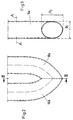
- a heat exchanger tube 14 placed such that it is initially based on a combustion chamber 12 in the there is a burner or on which a burner acts, essentially along a square outline is guided, being in the corner areas of the imagined Squares the curvature of the pipe according to the material specification is laid.
- the heat exchanger tube 14 After the heat exchanger tube 14 almost one complete circulation around the fan 10 is formed it returned with a change of direction of 180 °, forming a cantilevered bend 16 which according to the drawing, down depends and one sufficient to absorb the thermal expansion Distance from other system components.
- the heat exchanger tube 14 is then on the outline of the same square returned and ends in a not shown Connection. As long as the attachment points are sufficient are removed from the cantilevered bend 16, these are relieved of the thermal stresses that for the most part of the cantilevered bend 16 or the one formed thereby End section are included.
- the two pipe sections 16a and 16b meet at an acute angle in the region of the cantilevered bend 16.
- the heat exchanger tube has an essentially circular cross section with a diameter D 1 .
- the tube has an essentially elliptical cross section, the small axis of the ellipse having the length D 1 and the large axis of the ellipse having the length D 2 .
- D 2 is about 1.2 to 1.4 times D2, for example 1.3 times.
- the cross-sectional area of the heat exchanger tube 14 in the region of the bend 16 is approximately 20% to 40% larger than in the other regions of the tube 14.
- an enlarged tube cross section in the other bent regions of the heat exchanger tube, in particular in the Edge areas can be provided with a deflection of substantially 90 °.
Abstract
Description
Die Erfindung betrifft eine Wärmetauschereinrichtung mit einem Lüfterrad, insbesondere einem Radial-Lüfterrad, einem Brenner und zumindest einem dem Brenner zugeordneten Wärmetauscherrohr, welches das Lüfterrad umgibt.The invention relates to a heat exchanger device a fan wheel, in particular a radial fan wheel, a Burner and at least one associated with the burner Heat exchanger tube which surrounds the fan wheel.
Eine solche Wärmetauschereinrichtung ist aus der EP 0 526 768 B1 bekannt; sie wird zum Garen von Nahrungsmitteln in einem Garraum einer entsprechenden Vorrichtung eingesetzt. Such a heat exchanger device is known from EP 0 526 768 B1 known; it is used to cook food in a cooking chamber of a corresponding device.
Ein Problem bei gasbeheizten Wärmetauschern ist, daß durch die hohen Temperaturen Spannungen entstehen, die einerseits von den Rohren aufgenommen werden müssen, die andererseits das Rohr aber insbesondere an den Befestigungsstellen am Gehäuse, an einem Rahmen oder dergleichen belasten. Gleichzeitig ist einhoher Wirkungsgrad des Wärmeaustausches anzustreben. Die EP 0 526 768 B1 schlägt dazu vor, das Wärmetauscherrohr spiralförmig um das Lüfterrad zu führen, wodurch eine gleichmäßigere Wärmeausdehnung des Wärmetauscherrohres mit gleichzeitig optimiertem Wärmeaustausch erfolgen soll.A problem with gas heated heat exchangers is that the high temperatures create tensions on the one hand must be taken up by the pipes, on the other hand the pipe but especially at the attachment points on the housing, on a frame or the like strain. At the same time, heat exchange is highly efficient to strive for. EP 0 526 768 B1 suggests To do this, spiral the heat exchanger tube around the fan wheel lead, creating a more uniform thermal expansion of the heat exchanger tube with optimized at the same time Heat exchange should take place.
Es bleibt das Problem, daß weiterhin die Befestigungsstellen des Wärmetauscherrohres an der Gehäusewand oder dergleichen belastet werden. Dieses Problem zu lösen, hat sich die Erfindung zur Aufgabe gestellt.The problem remains that the attachment points continue of the heat exchanger tube on the housing wall or the like be charged. To solve this problem has set itself the task.
Dazu ist gemäß der Erfindung vorgesehen, daß bei der Wärmetauschereinrichtung der eingangs genannten Gattung das Wärmetauscherrohr in zumindest einem Abschnitt zu einer freikragenden Biegung gekrümmt ist. Diese freikragende Riegung nimmt die Wärmedehnungen auf, so daß die Befestigungsstellen des Wärmetauscherrohres weitgehend entlastet werden.For this purpose, it is provided according to the invention that in the heat exchanger device of the genus mentioned above Heat exchanger tube in at least one section to one cantilevered bend is curved. This cantilevered Riegung absorbs the thermal expansion, so that the fastening points the heat exchanger tube largely relieved will.
Bevorzugt weist das Wärmetauscherrohr im Bereich der freikragenden Biegung einen vergrößerten Querschnitt auf. Wegen der Umkehr der Strömungsrichtung ergibt sich im Bereich der Biegung aufgrund einer Wirbelbildung ein erhöhter Strömungswiderstand, der erfindungsgemäß durch die Querschnittserweiterung ausgeglichen wird. Idealerweise ist dieser erweiterte Querschnitt so bemessen, daß der Strömungswiderstand im Bereich der Biegung im wesentlichen derselbe wie in den beiden Rohrabschnitten ist, die zu der Biegung hin- bzw. von dieser wegführen. Damit wird die Gefahr einer lokalen Überhitzung vermieden.The heat exchanger tube preferably has in the region of the cantilever Bend an enlarged cross section. Because of the reversal of the flow direction results in Area of the bend increased due to a vortex formation Flow resistance, which by the invention Cross-sectional expansion is compensated. Ideally is this expanded cross section dimensioned so that the Flow resistance in the area of the bend essentially is the same as in the two pipe sections to which the Guide the bend towards or away from it. With that the Avoid danger of local overheating.
Ein vergrößerter Querschnitt im Bereich der freikragenden Biegung kann insbesondere dadurch erreicht werden, daß die beiden Rohrabschnitte, welche die freikragende Biegung bilden, in einem spitzen Winkel aufeinandertreffen.An enlarged cross section in the cantilever area Bend can be achieved in particular that the two pipe sections, which are the cantilevered bend form, meet at an acute angle.
Vorteilhafterweise besitzt das Wärmetauscherrohr im Bereich der freikragenden Biegung einen ovalen Querschnitt.The heat exchanger tube advantageously has Cantilever bend an oval Cross-section.
Bevorzugt kann die freikragende Biegung durch eine Richtungsänderung im Wärmetauscherrohr um 180° gebildet sein. Beispielsweise wird durch die freikragende Biegung ein horizontales oder vertikales Ende erzeugt, das zunächst mit hinreichendem Abstand zu anderen Systemkomponenten vorgesehen sein kann, so daß Wärmedehnungen ohne Probleme aufgenommen bzw. ausgeglichen werden können.The cantilevered bend can preferably be caused by a change in direction be formed by 180 ° in the heat exchanger tube. For example, the cantilevered bend horizontal or vertical end creates that first with a sufficient distance to other system components can be provided so that thermal expansion without problems can be included or compensated.
Weiter bevorzugt ist die freikragende Biegung entfernt von Befestigungsstellen des Wärmetauscherrohrs an einer Gehäusewand oder dergleichen vorgesehen.The cantilevered bend is more preferably removed from Fastening points of the heat exchanger tube on a housing wall or the like provided.
Gemäß einer bevorzugten Ausführungsform der Erfindung ist das Wärmetauscherrohr um das Lüfterrad entlang des Umrisses einer rechtwinkligen Fläche geführt. Das Wärmetauscherrohr umgibt das Gebläse dabei in Form eines Quadrats oder Rechteckes, wobei die Rohrkrümmungen in den jeweiligen Ecken dieses Rechteckes liegen. Dadurch wird eine besonders große Fläche für den Wärmeaustausch geschaffen. Außerdem ist diese Anordnung bei den üblichen quaderförmigen Geometrien von Räumen zur Wärmebehandlung von Speisen vorteilhaft, da auf diese Weise eine optimale Raumausnutzung erreicht wird.According to a preferred embodiment of the invention the heat exchanger tube around the fan wheel along the outline a rectangular surface. The heat exchanger tube surrounds the fan in the form of a square or rectangle, the pipe curvatures in the respective Corners of this rectangle. This makes one special created a large area for heat exchange. In addition, this arrangement is the usual cuboid Geometries of rooms for the heat treatment of food advantageous because in this way an optimal use of space is achieved.
Wenn die freikragende Biegung an der Stelle oder in der Nähe der Stelle eines vollständigen Umlaufs des Wärmetauscherrohres um das Lüfterrad vorgesehen ist, kann das Wärmetauscherrohr im Anschluß an die Biegung parallel zu der Herrührung zurückgeführt werden, so daß eine kompakte und einfache Anordnung des Wärmetauscherrohres getroffen werden kann.If the cantilevered bend at the point or in the Near the place of a complete circulation of the heat exchanger tube around the fan wheel, the heat exchanger tube following the bend parallel to the Mr. Touch can be returned, so that a compact and simple arrangement of the heat exchanger tube can be made can.
Die Erfindung macht es möglich, ohne kostenintensive Wellrohre auszukommen und insbesondere Wärmetauscherrohre zu verwenden, die zumindest an der Außenseite glatt sind. Damit ist eine hygienische, vorteilhafte Reinigung möglich. Außerdem kann das Rohr ausreichend massiv gestaltet werden, so daß die Gefahr mechanischer Beschädigungen gering ist und die Lebensdauer und Betriebssicherheit gewährleistet sind.The invention makes it possible without expensive corrugated pipes get along and in particular heat exchanger tubes use that are at least smooth on the outside. This enables hygienic, advantageous cleaning. In addition, the tube can be made sufficiently solid be so that the risk of mechanical damage is low is and the lifespan and operational safety are guaranteed.
Bevorzugt wird eine Wärmetauschereinrichtung, wie zuvor beschrieben, in einer Vorrichtung zur Wärmebehandlung von Speisen eingesetzt, wobei die Wärmetauschereinrichtung im Garraum der Vorrichtung angeordnet sein kann, ohne daß nachteilige Einflüsse auf die zu garenden Lebensmittel zu befürchten wären. Die einfachen Reinigungsmöglichkeiten stellen einen besonderen Vorteil der Wärmetauschereinrichtung für die gedachte Verwendung dar.A heat exchanger device is preferred, as before described in a device for heat treatment of Food used, the heat exchanger device in Cooking space of the device can be arranged without adverse influences on the food to be cooked would be feared. The simple cleaning options represent a particular advantage of the heat exchanger device for the intended use.
Im folgenden wird die Erfindung beispielhaft anhand der beigefügten schematischen Zeichnungen beschrieben. Hierbei zeigen
- Fig. 1
- eine schematische perspektivische Ansicht einer Wärmetauschereinrichtung gemäß einer ersten Ausführungsform der Erfindung und
- Fig. 2
- eine schematische Teilansicht der freikragenden Biegung bei einer zweiten Ausführungform der Erfindung.
- Fig.3
- einen Querschnitt entlang der Linie III-III in Fig. 2.
- Fig. 1
- is a schematic perspective view of a heat exchanger device according to a first embodiment of the invention and
- Fig. 2
- is a schematic partial view of the cantilever bend in a second embodiment of the invention.
- Fig. 3
- a cross section along the line III-III in Fig. 2nd
Bei den in Fig. 1 und Fig. 2 dargestellten Wärmetauschereinrichtungen sind sämtliche umgebenden Komponenten, wie Gehäuseteile, Befestigungsteile, Anschlüsse und dergleichen weggelassen.In the heat exchanger devices shown in FIGS. 1 and 2 are all surrounding components, such as Housing parts, fastening parts, connections and the like omitted.
Bei dem in Fig. 1 gezeigten Ausführungsbeispiel ist um ein
Radial-Lüfterrad 10, das durch einen nicht gezeigten Motor
angetrieben wird, ein Wärmetauscherrohr 14 derart gelegt,
daß es zunächst ausgehend von einer Brennkammer 12, in der
sich ein Brenner befindet, bzw. auf die ein Brenner einwirkt,
in wesentlichen entlang eines quadratischen Umrisses
geführt ist, wobei in den Eckbereichen des gedachten
Quadrates die Krümmung des Rohres nach Materialvorgabe
gelegt ist. Nachdem das Wärmetauscherrohr 14 nahezu einen
vollständigen Umlauf um das Gebläse 10 gebildet hat, wird
es mit einer Richtungsänderung von 180° zurückgeführt,
wobei eine freikragende Biegung 16 gebildet wird, die,
entsprechend der zeichnerischen Darstellung, nach unten
abhängt und einen zum Auffangen der Wärmedehnungen ausreichenden
Abstand von anderen Systemkomponenten aufweist.
Das Wärmetauscherrohr 14 wird dann am Umriß desselben Quadrates
zurückgeführt und mündet in einen nicht dargestellten
Anschluß. Solange die Befestigungsstellen ausreichend
von der freikragenden Biegung 16 entfernt sind, sind diese
von den Wärmespannungen entlastet, die zum größten Teil
von der freikragenden Biegung 16 bzw. dem dadurch gebildeten
Endabschnitt aufgenommen werden.In the embodiment shown in Fig. 1 is around
Bei dem in Fig. 2 dargestellten Ausführungsbeispiel der
Erfindung, das weitgehend dem Ausführungsbeispiel der Fig.
1 entspricht, treffen die beiden Rohrabschnitte 16a und
16b im Bereich der freikragenden Biegung 16 spitzwinklig
aufeinander. Abseits der freikragenden Biegung, z.B. auf
der Höhe der Linie A-A, hat das Wärmetauscherrohr einen im
wesentlichen kreisförmigen Querschnitt mit einem Durchmesser
D1. Im Bereich der freikragenden Biegung hingegen hat
das Rohr im wesentlichen einen elliptischen Querschnitt,
wobei die kleine Achse der Ellipse die Länge D1 und die
große Achse der Ellipse die Länge D2 hat. Typischerweise
beträgt D2 etwa das 1,2 bis 1,4-fache von D2, z.B. das 1,3-fache.
Damit wird im Bereich der Biegung 16 eine Vergrößerung
der Querschnittsfläche des Rohrs erreicht und damit
einer Vergrößerung des Strömungswiderstands in diesem Bereich
entgegengewirkt, der ansonsten aufgrund der
Richtungsumkehr im Bereich der Biegung 16 und der damit
verbundenen Wirbelbildung entstehen würde. Typischerweise
ist die Querschnittsfläche des Wärmetauscherrohrs 14 im
Bereich der Biegung 16 etwa 20% bis 40% größer als in den
anderen Bereichen des Rohrs 14. In einer Abwandlung der
dargestellten Ausführungsform kann auch ein vergrößerter
Rohrquerschnitt in den übrigen gebogenen Bereichen des
Wärmetauscherrohrs, insbesondere in den Kantenbereichen
mit einer Umlenkung von im wesentlichen 90° vorgesehen
sein. In the embodiment of the invention shown in FIG. 2, which largely corresponds to the embodiment of FIG. 1, the two
Die in der Beschreibung, in der Zeichnung sowie in den Ansprüchen offenbarten Merkmale der Erfindung können sowohl einzeln als auch in beliebiger Kombination für die Verwirklichung der Erfindung wesentlich sein. The in the description, in the drawing and in the Features of the invention disclosed in claims can be both individually as well as in any combination for the Realization of the invention may be essential.
- 1010th
- LüfterradFan wheel
- 1212th
- BrennkammerCombustion chamber
- 1414
- WärmetauscherrohrHeat exchanger tube
- 1616
- Freikragende BiegungCantilevered bend
- 16a, 16b16a, 16b
- Rohrabschnitte im Bereich der BiegungPipe sections in the area of the bend
Claims (10)
Applications Claiming Priority (4)
| Application Number | Priority Date | Filing Date | Title |
|---|---|---|---|
| DE19703319 | 1997-01-30 | ||
| DE19703319 | 1997-01-30 | ||
| DE19708231 | 1997-02-28 | ||
| DE19708231A DE19708231C2 (en) | 1997-01-30 | 1997-02-28 | Heat exchanger device for a device for heat treatment of food |
Publications (2)
| Publication Number | Publication Date |
|---|---|
| EP0856705A1 true EP0856705A1 (en) | 1998-08-05 |
| EP0856705B1 EP0856705B1 (en) | 2002-02-20 |
Family
ID=26033488
Family Applications (1)
| Application Number | Title | Priority Date | Filing Date |
|---|---|---|---|
| EP97120541A Expired - Lifetime EP0856705B1 (en) | 1997-01-30 | 1997-11-24 | Arrangement of heat exchanger |
Country Status (4)
| Country | Link |
|---|---|
| US (1) | US5915372A (en) |
| EP (1) | EP0856705B1 (en) |
| JP (1) | JP3021411B2 (en) |
| AT (1) | ATE213532T1 (en) |
Cited By (6)
| Publication number | Priority date | Publication date | Assignee | Title |
|---|---|---|---|---|
| EP0926447A1 (en) * | 1997-12-23 | 1999-06-30 | RATIONAL GmbH | Cooking apparatus with heat-recirculation |
| DE102004004393B3 (en) * | 2004-01-29 | 2005-05-25 | Rational Ag | Cooking device for cooking food comprises a device for receiving and dispensing a cleaning, clear rinsing and/or antiliming agent that is attached or provided in, in front of and/or behind a first opening in an air-guiding element |
| FR2899317A1 (en) * | 2006-04-03 | 2007-10-05 | Thirode Grandes Cuisines Poligny | Heat exchanger for gas burner of e.g. gas oven, has connecting rod fixed to large diameter tubular part and small diameter pipes, where tubular part, connecting rod and pipes form ring while leaving central space of ring to be free |
| DE202011005261U1 (en) | 2010-04-14 | 2011-10-27 | Jaroslav Klouda | Hot air heat exchanger for cooking appliances, such as combi steamers, baking and grilling appliances |
| ITTO20100632A1 (en) * | 2010-07-21 | 2012-01-22 | Premark Feg Llc | IMPROVED HEAT EXCHANGER FOR A PROCESSING DEVICE FOR FOOD AND OVEN EQUIPPED |
| US9372005B2 (en) | 2012-11-30 | 2016-06-21 | Alto-Shaam, Inc. | Heat exchanger for oven |
Families Citing this family (11)
| Publication number | Priority date | Publication date | Assignee | Title |
|---|---|---|---|---|
| IT1311159B1 (en) * | 1999-11-30 | 2002-03-04 | Angelo Grandi Cucine Spa | HEAT EXCHANGER DEVICE FOR OVENS USED FOR DIAL COOKING |
| NL1014044C2 (en) * | 2000-01-10 | 2001-07-19 | Levens Group B V | Oven heated by gas burner. |
| US6188045B1 (en) | 2000-04-03 | 2001-02-13 | Alto-Shaam, Inc. | Combination oven with three-stage water atomizer |
| US6346750B1 (en) * | 2000-04-28 | 2002-02-12 | Micron Technology, Inc. | Resistance-reducing conductive adhesives for attachment of electronic components |
| US6371104B1 (en) | 2000-07-21 | 2002-04-16 | Wayne/Scott Fetzer Company | Convection oven with gas burner |
| US7017571B2 (en) * | 2003-06-18 | 2006-03-28 | Convotherm Elektrogeräte GmbH | Heat exchanger device |
| IT1392974B1 (en) | 2009-02-17 | 2012-04-02 | Premark Feg Llc | HEAT EXCHANGER FOR A PROCESSING DEVICE FOR FOOD AND OVEN PROVIDED |
| CN105143773A (en) * | 2013-06-07 | 2015-12-09 | 因诺恩股份有限公司 | Heat exchanger for cooking apparatus |
| USD762289S1 (en) * | 2014-07-15 | 2016-07-26 | Dometic Sweden Ab | Heat exchanger |
| IT201600094910A1 (en) * | 2016-09-21 | 2018-03-21 | Steelform Srl | HEAT EXCHANGER FOR COOKING OVENS |
| JP6860374B2 (en) * | 2017-02-17 | 2021-04-14 | ホシザキ株式会社 | Cooker |
Citations (2)
| Publication number | Priority date | Publication date | Assignee | Title |
|---|---|---|---|---|
| US3605717A (en) * | 1969-11-10 | 1971-09-20 | Crown X Inc | Convection oven |
| US4648377A (en) * | 1986-05-01 | 1987-03-10 | Hobart Corporation | Gas convection oven and heat exchanger therefor |
Family Cites Families (6)
| Publication number | Priority date | Publication date | Assignee | Title |
|---|---|---|---|---|
| DE1841213U (en) * | 1961-09-07 | 1961-11-09 | Fernwaerme Karl Kempf G M B H | COMPENSATION ELEMENT COMPOSING AN ELBOW PIPE FOR BIG PIPELINE. |
| US5165889A (en) * | 1989-05-19 | 1992-11-24 | Import-Export Research And Development, Inc. | Gas convection oven with heat exchanger and baffles |
| US5060722A (en) * | 1990-11-06 | 1991-10-29 | American Standard, Inc. | Furnace heat exchanger |
| IT1253697B (en) * | 1991-08-05 | 1995-08-22 | Zanussi Grandi Impianti Spa | FORCED CONVECTION GAS COOKING OVEN. |
| US5309890A (en) * | 1993-07-30 | 1994-05-10 | Carrier Corporation | Dual-sided condensate trap for furnace |
| US5664555A (en) * | 1995-09-01 | 1997-09-09 | Empire Comfort Systems, Inc. | Wall heater with improved heat exchanger |
-
1997
- 1997-11-24 AT AT97120541T patent/ATE213532T1/en not_active IP Right Cessation
- 1997-11-24 EP EP97120541A patent/EP0856705B1/en not_active Expired - Lifetime
-
1998
- 1998-01-29 US US09/015,120 patent/US5915372A/en not_active Expired - Lifetime
- 1998-01-29 JP JP10016794A patent/JP3021411B2/en not_active Expired - Fee Related
Patent Citations (2)
| Publication number | Priority date | Publication date | Assignee | Title |
|---|---|---|---|---|
| US3605717A (en) * | 1969-11-10 | 1971-09-20 | Crown X Inc | Convection oven |
| US4648377A (en) * | 1986-05-01 | 1987-03-10 | Hobart Corporation | Gas convection oven and heat exchanger therefor |
Cited By (9)
| Publication number | Priority date | Publication date | Assignee | Title |
|---|---|---|---|---|
| EP0926447A1 (en) * | 1997-12-23 | 1999-06-30 | RATIONAL GmbH | Cooking apparatus with heat-recirculation |
| DE102004004393B3 (en) * | 2004-01-29 | 2005-05-25 | Rational Ag | Cooking device for cooking food comprises a device for receiving and dispensing a cleaning, clear rinsing and/or antiliming agent that is attached or provided in, in front of and/or behind a first opening in an air-guiding element |
| FR2899317A1 (en) * | 2006-04-03 | 2007-10-05 | Thirode Grandes Cuisines Poligny | Heat exchanger for gas burner of e.g. gas oven, has connecting rod fixed to large diameter tubular part and small diameter pipes, where tubular part, connecting rod and pipes form ring while leaving central space of ring to be free |
| EP1843101A3 (en) * | 2006-04-03 | 2012-12-05 | Thirode Grandes Cuisines Poligny | Heat-exchange device for a gas burner. |
| DE202011005261U1 (en) | 2010-04-14 | 2011-10-27 | Jaroslav Klouda | Hot air heat exchanger for cooking appliances, such as combi steamers, baking and grilling appliances |
| DE102011017024A1 (en) | 2010-04-14 | 2012-01-12 | Jaroslav Klouda | Thermal equipment for a cooking equipment, particularly comb steamer and rotational grill device, particularly cooking-, baking-, heating- or grill equipment for food preparation, has cooking chamber with heating system |
| ITTO20100632A1 (en) * | 2010-07-21 | 2012-01-22 | Premark Feg Llc | IMPROVED HEAT EXCHANGER FOR A PROCESSING DEVICE FOR FOOD AND OVEN EQUIPPED |
| WO2012012479A1 (en) * | 2010-07-21 | 2012-01-26 | Premark Feg L.L.C. | Food processing device with a heat exchanger |
| US9372005B2 (en) | 2012-11-30 | 2016-06-21 | Alto-Shaam, Inc. | Heat exchanger for oven |
Also Published As
| Publication number | Publication date |
|---|---|
| EP0856705B1 (en) | 2002-02-20 |
| ATE213532T1 (en) | 2002-03-15 |
| JP3021411B2 (en) | 2000-03-15 |
| JPH10246438A (en) | 1998-09-14 |
| US5915372A (en) | 1999-06-29 |
Similar Documents
| Publication | Publication Date | Title |
|---|---|---|
| EP0856705B1 (en) | Arrangement of heat exchanger | |
| DE1802196A1 (en) | Burner unit for radiator | |
| DE3630502A1 (en) | PIPE GRID FOR GUIDING THE TUBES OF EXAMPLE STEAM GENERATORS | |
| DE19708231C2 (en) | Heat exchanger device for a device for heat treatment of food | |
| EP0401543B1 (en) | Neat-exchanger apparatus, especially for a gas or oil fixed water heater | |
| DE3029298C2 (en) | Space heater for small rooms | |
| DE2245357A1 (en) | HEAT EXCHANGER | |
| AT403259B (en) | HEAT EXCHANGER | |
| DE3400377A1 (en) | Heat exchanger for heating plants | |
| DE2126226A1 (en) | Heat exchanger | |
| DE1751641A1 (en) | Forced once-through steam generator with wall tubing formed from vertical welded tubes and a method for operating the steam generator | |
| AT395209B (en) | HEATING DEVICE | |
| DE2539933A1 (en) | USE FOR A SMOKE PIPE OF A HEATING BOILER TO INCREASE THE FLUE GAS SWIRLING | |
| EP0838634A2 (en) | Gas combination grill, in particular sausage grill | |
| DE2552388B2 (en) | Heating boilers for liquid or gaseous fuels | |
| DE750482C (en) | Arrangement for supporting heated pipe coils | |
| DE2807166C2 (en) | ||
| DE3624394C2 (en) | radiator | |
| DE2149840C3 (en) | Hot water boiler for a collective heating system | |
| DE1751641C (en) | Forced once-through steam generator with wall tubing made of vertical welded tubes | |
| DE19545228C1 (en) | Combustion-chamber tube wall | |
| DE6946628U (en) | SMOKE OR HEATING GAS EXHAUST PIPES FOR BOILER. | |
| EP0689013A1 (en) | Small boiler with domestic hot water production | |
| AT257106B (en) | Standing stove in prismatic shape with a water jacket enclosing the firebox with smooth interior walls | |
| DE1245983B (en) | Combustion chamber wall formed from parallel tubes |
Legal Events
| Date | Code | Title | Description |
|---|---|---|---|
| PUAI | Public reference made under article 153(3) epc to a published international application that has entered the european phase |
Free format text: ORIGINAL CODE: 0009012 |
|
| AK | Designated contracting states |
Kind code of ref document: A1 Designated state(s): AT BE CH DE DK ES FI FR GB GR IE IT LI LU MC NL PT SE |
|
| AX | Request for extension of the european patent |
Free format text: AL;LT;LV;MK;RO;SI |
|
| RTI1 | Title (correction) | ||
| 17P | Request for examination filed |
Effective date: 19980828 |
|
| AKX | Designation fees paid |
Free format text: AT BE CH DE DK ES FI FR GB GR IE IT LI LU MC NL PT SE |
|
| RBV | Designated contracting states (corrected) |
Designated state(s): AT BE CH DE DK ES FI FR GB GR IE IT LI LU MC NL PT SE |
|
| RAP1 | Party data changed (applicant data changed or rights of an application transferred) |
Owner name: RATIONAL AG |
|
| 17Q | First examination report despatched |
Effective date: 20001024 |
|
| GRAG | Despatch of communication of intention to grant |
Free format text: ORIGINAL CODE: EPIDOS AGRA |
|
| GRAG | Despatch of communication of intention to grant |
Free format text: ORIGINAL CODE: EPIDOS AGRA |
|
| GRAH | Despatch of communication of intention to grant a patent |
Free format text: ORIGINAL CODE: EPIDOS IGRA |
|
| GRAH | Despatch of communication of intention to grant a patent |
Free format text: ORIGINAL CODE: EPIDOS IGRA |
|
| REG | Reference to a national code |
Ref country code: GB Ref legal event code: IF02 |
|
| GRAA | (expected) grant |
Free format text: ORIGINAL CODE: 0009210 |
|
| AK | Designated contracting states |
Kind code of ref document: B1 Designated state(s): AT BE CH DE DK ES FI FR GB GR IE IT LI LU MC NL PT SE |
|
| PG25 | Lapsed in a contracting state [announced via postgrant information from national office to epo] |
Ref country code: NL Free format text: LAPSE BECAUSE OF FAILURE TO SUBMIT A TRANSLATION OF THE DESCRIPTION OR TO PAY THE FEE WITHIN THE PRESCRIBED TIME-LIMIT Effective date: 20020220 Ref country code: IE Free format text: LAPSE BECAUSE OF FAILURE TO SUBMIT A TRANSLATION OF THE DESCRIPTION OR TO PAY THE FEE WITHIN THE PRESCRIBED TIME-LIMIT Effective date: 20020220 Ref country code: GR Free format text: LAPSE BECAUSE OF FAILURE TO SUBMIT A TRANSLATION OF THE DESCRIPTION OR TO PAY THE FEE WITHIN THE PRESCRIBED TIME-LIMIT Effective date: 20020220 Ref country code: FI Free format text: LAPSE BECAUSE OF FAILURE TO SUBMIT A TRANSLATION OF THE DESCRIPTION OR TO PAY THE FEE WITHIN THE PRESCRIBED TIME-LIMIT Effective date: 20020220 |
|
| REF | Corresponds to: |
Ref document number: 213532 Country of ref document: AT Date of ref document: 20020315 Kind code of ref document: T |
|
| REG | Reference to a national code |
Ref country code: CH Ref legal event code: EP |
|
| GBT | Gb: translation of ep patent filed (gb section 77(6)(a)/1977) |
Effective date: 20020220 |
|
| REF | Corresponds to: |
Ref document number: 59706433 Country of ref document: DE Date of ref document: 20020328 |
|
| PG25 | Lapsed in a contracting state [announced via postgrant information from national office to epo] |
Ref country code: SE Free format text: LAPSE BECAUSE OF FAILURE TO SUBMIT A TRANSLATION OF THE DESCRIPTION OR TO PAY THE FEE WITHIN THE PRESCRIBED TIME-LIMIT Effective date: 20020520 Ref country code: PT Free format text: LAPSE BECAUSE OF FAILURE TO SUBMIT A TRANSLATION OF THE DESCRIPTION OR TO PAY THE FEE WITHIN THE PRESCRIBED TIME-LIMIT Effective date: 20020520 Ref country code: DK Free format text: LAPSE BECAUSE OF FAILURE TO SUBMIT A TRANSLATION OF THE DESCRIPTION OR TO PAY THE FEE WITHIN THE PRESCRIBED TIME-LIMIT Effective date: 20020520 |
|
| NLV1 | Nl: lapsed or annulled due to failure to fulfill the requirements of art. 29p and 29m of the patents act | ||
| ET | Fr: translation filed | ||
| PG25 | Lapsed in a contracting state [announced via postgrant information from national office to epo] |
Ref country code: ES Free format text: LAPSE BECAUSE OF FAILURE TO SUBMIT A TRANSLATION OF THE DESCRIPTION OR TO PAY THE FEE WITHIN THE PRESCRIBED TIME-LIMIT Effective date: 20020829 |
|
| REG | Reference to a national code |
Ref country code: IE Ref legal event code: FD4D |
|
| PG25 | Lapsed in a contracting state [announced via postgrant information from national office to epo] |
Ref country code: LU Free format text: LAPSE BECAUSE OF NON-PAYMENT OF DUE FEES Effective date: 20021124 Ref country code: AT Free format text: LAPSE BECAUSE OF NON-PAYMENT OF DUE FEES Effective date: 20021124 |
|
| PG25 | Lapsed in a contracting state [announced via postgrant information from national office to epo] |
Ref country code: LI Free format text: LAPSE BECAUSE OF NON-PAYMENT OF DUE FEES Effective date: 20021130 Ref country code: CH Free format text: LAPSE BECAUSE OF NON-PAYMENT OF DUE FEES Effective date: 20021130 Ref country code: BE Free format text: LAPSE BECAUSE OF NON-PAYMENT OF DUE FEES Effective date: 20021130 |
|
| PLBE | No opposition filed within time limit |
Free format text: ORIGINAL CODE: 0009261 |
|
| STAA | Information on the status of an ep patent application or granted ep patent |
Free format text: STATUS: NO OPPOSITION FILED WITHIN TIME LIMIT |
|
| 26N | No opposition filed |
Effective date: 20021121 |
|
| BERE | Be: lapsed |
Owner name: *RATIONAL A.G. Effective date: 20021130 |
|
| PG25 | Lapsed in a contracting state [announced via postgrant information from national office to epo] |
Ref country code: MC Free format text: LAPSE BECAUSE OF NON-PAYMENT OF DUE FEES Effective date: 20030601 |
|
| REG | Reference to a national code |
Ref country code: CH Ref legal event code: PL |
|
| PGFP | Annual fee paid to national office [announced via postgrant information from national office to epo] |
Ref country code: GB Payment date: 20141120 Year of fee payment: 18 |
|
| REG | Reference to a national code |
Ref country code: FR Ref legal event code: PLFP Year of fee payment: 19 |
|
| GBPC | Gb: european patent ceased through non-payment of renewal fee |
Effective date: 20151124 |
|
| PG25 | Lapsed in a contracting state [announced via postgrant information from national office to epo] |
Ref country code: GB Free format text: LAPSE BECAUSE OF NON-PAYMENT OF DUE FEES Effective date: 20151124 |
|
| REG | Reference to a national code |
Ref country code: FR Ref legal event code: PLFP Year of fee payment: 20 |
|
| PGFP | Annual fee paid to national office [announced via postgrant information from national office to epo] |
Ref country code: FR Payment date: 20161124 Year of fee payment: 20 Ref country code: DE Payment date: 20161125 Year of fee payment: 20 |
|
| PGFP | Annual fee paid to national office [announced via postgrant information from national office to epo] |
Ref country code: IT Payment date: 20161124 Year of fee payment: 20 |
|
| REG | Reference to a national code |
Ref country code: DE Ref legal event code: R071 Ref document number: 59706433 Country of ref document: DE |