EP0856701A2 - Ancrage de support - Google Patents
Ancrage de support Download PDFInfo
- Publication number
- EP0856701A2 EP0856701A2 EP97121812A EP97121812A EP0856701A2 EP 0856701 A2 EP0856701 A2 EP 0856701A2 EP 97121812 A EP97121812 A EP 97121812A EP 97121812 A EP97121812 A EP 97121812A EP 0856701 A2 EP0856701 A2 EP 0856701A2
- Authority
- EP
- European Patent Office
- Prior art keywords
- base part
- arms
- reinforcement
- anchor
- less
- Prior art date
- Legal status (The legal status is an assumption and is not a legal conclusion. Google has not performed a legal analysis and makes no representation as to the accuracy of the status listed.)
- Granted
Links
Images


Classifications
-
- F—MECHANICAL ENGINEERING; LIGHTING; HEATING; WEAPONS; BLASTING
- F23—COMBUSTION APPARATUS; COMBUSTION PROCESSES
- F23M—CASINGS, LININGS, WALLS OR DOORS SPECIALLY ADAPTED FOR COMBUSTION CHAMBERS, e.g. FIREBRIDGES; DEVICES FOR DEFLECTING AIR, FLAMES OR COMBUSTION PRODUCTS IN COMBUSTION CHAMBERS; SAFETY ARRANGEMENTS SPECIALLY ADAPTED FOR COMBUSTION APPARATUS; DETAILS OF COMBUSTION CHAMBERS, NOT OTHERWISE PROVIDED FOR
- F23M5/00—Casings; Linings; Walls
- F23M5/08—Cooling thereof; Tube walls
-
- F—MECHANICAL ENGINEERING; LIGHTING; HEATING; WEAPONS; BLASTING
- F23—COMBUSTION APPARATUS; COMBUSTION PROCESSES
- F23M—CASINGS, LININGS, WALLS OR DOORS SPECIALLY ADAPTED FOR COMBUSTION CHAMBERS, e.g. FIREBRIDGES; DEVICES FOR DEFLECTING AIR, FLAMES OR COMBUSTION PRODUCTS IN COMBUSTION CHAMBERS; SAFETY ARRANGEMENTS SPECIALLY ADAPTED FOR COMBUSTION APPARATUS; DETAILS OF COMBUSTION CHAMBERS, NOT OTHERWISE PROVIDED FOR
- F23M5/00—Casings; Linings; Walls
- F23M5/04—Supports for linings
Definitions
- the invention relates to a reinforcement anchor on a wall is attached and the reinforcement one on the wall applied further solid lining (coating) is used.
- the newly developed reinforcement anchor is special for the attachment to so-called fin tube walls.
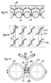
- Fin tube walls are analogous to FIG. 1 (prior art) built up. They consist of tubular elements 10 (hereinafter referred to as pipes) and the pipes 10 connecting Surface sections 12. While one side of the fin tube wall is covered by a refractory lining 14, on insulation on the other side Mineral wool must be applied.
- tubular elements 10 hereinafter referred to as pipes
- refractory lining 14 While one side of the fin tube wall is covered by a refractory lining 14, on insulation on the other side Mineral wool must be applied.
- Such fin tube walls are used in Power plants, waste incineration plants or the like.
- the shaft anchors run exclusively in the axial direction of the Tubes 10 ( Figure 2, right representation) and are only through To fix hand welding. Such a process is for one is complex and the other is not optimal Reinforcing effect for the refractory lining 14.
- the slot pins are identified as 16a in FIG also by hand welding onto the surface sections 12 welded on and then with a wedge along a central one Slot divided in the axial direction, as by the reference numeral 16b indicated.
- the disadvantage here is that for Reinforcement function important free end areas of the Reinforcement anchor 16 has a very small cross-sectional area have and accordingly do not absorb high loads can.
- the cross-sectional area of the angled free End areas of the slot pins is only about 30% of the Cross-sectional area of the slot pins at the weld, since also the axial slot (before bending) already material takes away.
- the object of the invention is to provide a reinforcement anchor mentioned type, especially for use Fin tube walls, to provide the avoids the aforementioned disadvantages, in particular easily assembled and can absorb great forces.
- the invention is based on the knowledge that a appropriate reinforcement anchor must be designed so that it with the help of a stud welding technique on the above Surface sections between the pipes can be attached a largely constant material thickness over its has entire longitudinal extent and shaped at the same time is that it is the most critical for the reinforcement function Covering the area around the pipes.
- the reinforcement anchor which is preferably in one piece (one piece) is thus essentially comprised of two sections are designed differently and have different functions fulfill.
- the U- or V-shaped base part is used for attachment on the fin tube wall, in the area of the entrance mentioned surface sections between adjacent pipes. This done by stud welding, preferably by means of Arc. In this procedure, there is a gap between the base part and on the short side of the metal wall an arc of high current ignited. The arc melts both parts, the parts are put together and the power is turned off.
- the process can be carried out using drawn ignition (DVS leaflet 0902) as well as with tip ignition (DVS leaflet 0903).
- one more or less point weld connection to the wall In the case of a V-shaped base part, one more or less point weld connection to the wall. In the case of one U-shaped base part is more or less linear or rectangular welded connection to the wall.
- Welding aid an adapter in which the armature anchor in front of the Welding process is aligned and held
- the orientation of the anchor usually be such that the plane spanned by the legs of the base part parallel for the longitudinal extension of the pipes and perpendicular to the wall, as shown in the following description of the figures is.
- the arms extend accordingly (both vertically and also viewed parallel to the wall) at a certain angle, which should be greater than 0 but less than 90 °.
- the arms are not perpendicular to the Axial direction of the pipes, but at a certain angle starting from the connection area to the base part, rising slightly (i.e. according to the shape of the neighboring pipes).
- a reinforcement anchor has proven to be particularly advantageous, the base part of which has a V-shape (FIG. 5) and which is designed S-shaped in the top view, preferably with one stretched S shape ".
- the reinforcement anchor can avoid as much as possible at least partially covering its surface with a melting or burning out under the influence of temperature Own material.
- This cover can, for example, in the form of Plastic caps are made on the free ends of the arms be plugged on.
- the cover can also be made from a Arms fully or partially covering Plastic coating exist that under the influence of temperature (under conditions of use) melts and so - like that called caps - a space between the reinforcement anchor and the refractory lining creates the thermal one Compensates for changes in length.
- the invention is based on a Embodiment described in more detail.
- Figures 4a, 4b and 4c show an inventive Reinforcement anchors in different views, each strong schematized.
- Figure 4a can be the one already known from Figures 1 to 3 remove the basic structure of a fin tube wall.
- FIG. 4c shows the welding aid 18 used for this with a receiving opening 20 for assembling the armature 16 and a chamber 22 formed on the underside into which the tip end 16s of the V-shaped base part 16v of the armature 16 protrudes.
- the armature 16 can be used for arc welding be held securely between adjacent tubes 10.
- At the A welding process forms in the chamber 22 Protective gas atmosphere that supports the welding process.
- a variety of anchors 16 are placed on the fin tube wall welded on and there is then an arrangement as in Figure 4b shown.
- the arms 24 of the reinforcement anchor 16 Connect materially to the V-shaped base part 16v.
- the arms 24 each extend at an angle ⁇ of approx. 45 ° to the plane spanned by the V-shaped base part 16v E1.
- the arms 24 are angled, here in each case an angle ⁇ of approximately 55 °.
- FIGS. 5 and 6 The shape of the anchor is shown in FIGS. 5 and 6 in exemplary version with V-shaped base part 16v (Figure 5) and U-shaped base part ( Figure 6) and twice angled arms 24 with attached at the end Plastic caps 26.
Landscapes
- Engineering & Computer Science (AREA)
- Chemical & Material Sciences (AREA)
- Combustion & Propulsion (AREA)
- Mechanical Engineering (AREA)
- General Engineering & Computer Science (AREA)
- Furnace Housings, Linings, Walls, And Ceilings (AREA)
- Reinforcement Elements For Buildings (AREA)
Priority Applications (1)
| Application Number | Priority Date | Filing Date | Title |
|---|---|---|---|
| DK97121812T DK0856701T3 (da) | 1997-01-31 | 1997-12-11 | Armeringsanker |
Applications Claiming Priority (2)
| Application Number | Priority Date | Filing Date | Title |
|---|---|---|---|
| DE29701591U DE29701591U1 (de) | 1997-01-31 | 1997-01-31 | Armierungsanker |
| DE29701591U | 1997-01-31 |
Publications (3)
| Publication Number | Publication Date |
|---|---|
| EP0856701A2 true EP0856701A2 (fr) | 1998-08-05 |
| EP0856701A3 EP0856701A3 (fr) | 1998-11-11 |
| EP0856701B1 EP0856701B1 (fr) | 2000-02-09 |
Family
ID=8035274
Family Applications (1)
| Application Number | Title | Priority Date | Filing Date |
|---|---|---|---|
| EP97121812A Expired - Lifetime EP0856701B1 (fr) | 1997-01-31 | 1997-12-11 | Ancrage de support |
Country Status (4)
| Country | Link |
|---|---|
| EP (1) | EP0856701B1 (fr) |
| AT (1) | ATE189739T1 (fr) |
| DE (2) | DE29701591U1 (fr) |
| DK (1) | DK0856701T3 (fr) |
Cited By (3)
| Publication number | Priority date | Publication date | Assignee | Title |
|---|---|---|---|---|
| EP1124094A1 (fr) * | 2000-02-08 | 2001-08-16 | Didier-Werke Ag | Brique réfractaire et construction de paroi de four associée |
| EP1862738A3 (fr) * | 2006-06-03 | 2008-02-20 | Jünger + Gräter GmbH Feuerfestbau | Procédé pour chauffer à sec un recouvrement de réfractaire et dispositif pour mettre en oeuvre le procédé |
| DE102008014984B3 (de) * | 2008-03-19 | 2009-08-27 | Jünger & Gräter GmbH Feuerfestbau | Einstückiger Stahlanker zur Verankerung ungeformter feuerfester Baustoffe |
Families Citing this family (2)
| Publication number | Priority date | Publication date | Assignee | Title |
|---|---|---|---|---|
| DE59801354D1 (de) * | 1997-11-18 | 2001-10-04 | Mokesys Ag Birsfelden | Feuerfeste rohrwandverkleidung |
| DE102005026530A1 (de) * | 2005-06-08 | 2006-12-14 | Lars Bolte | Metallisches Verankerungselement, insbesondere für feuerfeste Auskleidungen |
Family Cites Families (5)
| Publication number | Priority date | Publication date | Assignee | Title |
|---|---|---|---|---|
| US3336712A (en) * | 1964-09-30 | 1967-08-22 | Gregory Ind Inc | End weldable stud |
| US4414786A (en) * | 1980-03-28 | 1983-11-15 | Frahme Carl E | Heat insulating module for high temperature chambers |
| US4763584A (en) * | 1987-03-02 | 1988-08-16 | Combustion Engineering, Inc. | Means of attaching refractory to a furnace wall |
| US5618491A (en) * | 1996-02-22 | 1997-04-08 | Trw, Inc. | Studs for boilers and other high temperature applications |
| DE19611532C1 (de) * | 1996-03-23 | 1997-06-12 | Didier Werke Ag | Feuerraumwandung |
-
1997
- 1997-01-31 DE DE29701591U patent/DE29701591U1/de not_active Expired - Lifetime
- 1997-12-11 DE DE59701109T patent/DE59701109D1/de not_active Expired - Lifetime
- 1997-12-11 EP EP97121812A patent/EP0856701B1/fr not_active Expired - Lifetime
- 1997-12-11 AT AT97121812T patent/ATE189739T1/de active
- 1997-12-11 DK DK97121812T patent/DK0856701T3/da active
Non-Patent Citations (1)
| Title |
|---|
| None |
Cited By (4)
| Publication number | Priority date | Publication date | Assignee | Title |
|---|---|---|---|---|
| EP1124094A1 (fr) * | 2000-02-08 | 2001-08-16 | Didier-Werke Ag | Brique réfractaire et construction de paroi de four associée |
| US6487980B2 (en) | 2000-02-08 | 2002-12-03 | Didier-Werke Ag | Refractory ceramic plate and accompanying wall structure for an incinerator |
| EP1862738A3 (fr) * | 2006-06-03 | 2008-02-20 | Jünger + Gräter GmbH Feuerfestbau | Procédé pour chauffer à sec un recouvrement de réfractaire et dispositif pour mettre en oeuvre le procédé |
| DE102008014984B3 (de) * | 2008-03-19 | 2009-08-27 | Jünger & Gräter GmbH Feuerfestbau | Einstückiger Stahlanker zur Verankerung ungeformter feuerfester Baustoffe |
Also Published As
| Publication number | Publication date |
|---|---|
| DK0856701T3 (da) | 2000-07-24 |
| EP0856701A3 (fr) | 1998-11-11 |
| DE29701591U1 (de) | 1997-03-27 |
| DE59701109D1 (de) | 2000-03-16 |
| EP0856701B1 (fr) | 2000-02-09 |
| ATE189739T1 (de) | 2000-02-15 |
Similar Documents
| Publication | Publication Date | Title |
|---|---|---|
| EP0754824B1 (fr) | Longerons en treillis et structure de toit avec bâches et une pluralité de longerons en treillis supportant les bâches | |
| DE2522650A1 (de) | Waermeisolierungsbauteil fuer einen zylindrischen koerper und verfahren zur waermeisolierung eines zylindrischen koerpers | |
| DE102007036289A1 (de) | Verfahren und eine Vorrichtung zum Schweißen von Rundnähten | |
| DE2705843A1 (de) | Hitzebestaendige verkleidung | |
| EP0856701B1 (fr) | Ancrage de support | |
| EP0148434B1 (fr) | Conteneur pour gaz à haute température avec un revêtement isolant fait de plaques qui se recouvrent | |
| DE3874560T2 (de) | Aus bauteilen bestehende ofenauskleidung und werkstoffsystem dafuer. | |
| DE19631291A1 (de) | Isolationsverkleidung | |
| DE102017207053B4 (de) | Abgasrohr sowie Verfahren zum Ablängen eines Abgasrohres | |
| EP2388521A2 (fr) | Habillage pour une paroi tubulaire à ailettes d'un four de combustion | |
| DE3145420A1 (de) | Vorrichtung und verfahren zum reparieren oder ersetzen von verschleissstangen an kesselrohren | |
| EP0939270B1 (fr) | Dispositif avec un tube à jet | |
| DE60212584T2 (de) | Elektrodendichtung für einen lichtbogenofen | |
| DE2610978C2 (de) | Ofenauskleidung | |
| DE3533982C2 (fr) | ||
| EP0209703B1 (fr) | Cartouche incandescente pour fours, en particulier pour chaudières ainsi que four avec une telle cartouche | |
| DE19814723C1 (de) | Halter für Steinplatten | |
| EP1347534A2 (fr) | Borne de connexion et dispositif de mise à la terre | |
| DE3304745C2 (fr) | ||
| DE3800731C1 (en) | Angle-adjustable pipe bends comprising at least two pieces | |
| DE8407841U1 (de) | Feuerfeste ummantelung fuer langgestreckte bauteile in oefen | |
| DE3419335A1 (de) | Blaslanze | |
| DE2849504A1 (de) | Tauchlanze zum einblasen von gasen oder pulverisierten feststoffen in ein metallbad, insbesondere eine stahlschmelze | |
| DE102007025761B4 (de) | Flammrohr | |
| DE19804311A1 (de) | Verankerungsvorrichtung für Stahlrohraggregate abdeckende Steinplatten |
Legal Events
| Date | Code | Title | Description |
|---|---|---|---|
| PUAI | Public reference made under article 153(3) epc to a published international application that has entered the european phase |
Free format text: ORIGINAL CODE: 0009012 |
|
| AK | Designated contracting states |
Kind code of ref document: A2 Designated state(s): AT CH DE DK FR GB LI NL SE |
|
| AX | Request for extension of the european patent |
Free format text: AL;LT;LV;MK;RO;SI |
|
| PUAL | Search report despatched |
Free format text: ORIGINAL CODE: 0009013 |
|
| AK | Designated contracting states |
Kind code of ref document: A3 Designated state(s): AT BE CH DE DK ES FI FR GB GR IE IT LI LU MC NL PT SE |
|
| AX | Request for extension of the european patent |
Free format text: AL;LT;LV;MK;RO;SI |
|
| 17P | Request for examination filed |
Effective date: 19981117 |
|
| GRAG | Despatch of communication of intention to grant |
Free format text: ORIGINAL CODE: EPIDOS AGRA |
|
| GRAG | Despatch of communication of intention to grant |
Free format text: ORIGINAL CODE: EPIDOS AGRA |
|
| GRAH | Despatch of communication of intention to grant a patent |
Free format text: ORIGINAL CODE: EPIDOS IGRA |
|
| 17Q | First examination report despatched |
Effective date: 19990407 |
|
| GRAH | Despatch of communication of intention to grant a patent |
Free format text: ORIGINAL CODE: EPIDOS IGRA |
|
| AKX | Designation fees paid |
Free format text: AT CH DE DK FR GB LI NL SE |
|
| GRAA | (expected) grant |
Free format text: ORIGINAL CODE: 0009210 |
|
| AK | Designated contracting states |
Kind code of ref document: B1 Designated state(s): AT CH DE DK FR GB LI NL SE |
|
| REF | Corresponds to: |
Ref document number: 189739 Country of ref document: AT Date of ref document: 20000215 Kind code of ref document: T |
|
| REG | Reference to a national code |
Ref country code: CH Ref legal event code: EP |
|
| REG | Reference to a national code |
Ref country code: CH Ref legal event code: NV Representative=s name: HANS RUDOLF GACHNANG PATENTANWALT |
|
| REF | Corresponds to: |
Ref document number: 59701109 Country of ref document: DE Date of ref document: 20000316 |
|
| GBT | Gb: translation of ep patent filed (gb section 77(6)(a)/1977) |
Effective date: 20000407 |
|
| ET | Fr: translation filed | ||
| REG | Reference to a national code |
Ref country code: DK Ref legal event code: T3 |
|
| PLBE | No opposition filed within time limit |
Free format text: ORIGINAL CODE: 0009261 |
|
| STAA | Information on the status of an ep patent application or granted ep patent |
Free format text: STATUS: NO OPPOSITION FILED WITHIN TIME LIMIT |
|
| 26N | No opposition filed | ||
| REG | Reference to a national code |
Ref country code: GB Ref legal event code: IF02 |
|
| REG | Reference to a national code |
Ref country code: DE Ref legal event code: R008 Ref document number: 59701109 Country of ref document: DE |
|
| REG | Reference to a national code |
Ref country code: DE Ref legal event code: R082 Ref document number: 59701109 Country of ref document: DE Representative=s name: GRUENECKER, KINKELDEY, STOCKMAIR & SCHWANHAEUS, DE |
|
| REG | Reference to a national code |
Ref country code: DE Ref legal event code: R097 Ref document number: 59701109 Country of ref document: DE |
|
| REG | Reference to a national code |
Ref country code: DE Ref legal event code: R082 Ref document number: 59701109 Country of ref document: DE Representative=s name: GRUENECKER PATENT- UND RECHTSANWAELTE PARTG MB, DE Effective date: 20121218 Ref country code: DE Ref legal event code: R082 Ref document number: 59701109 Country of ref document: DE Representative=s name: GRUENECKER, KINKELDEY, STOCKMAIR & SCHWANHAEUS, DE Effective date: 20121218 Ref country code: DE Ref legal event code: R081 Ref document number: 59701109 Country of ref document: DE Owner name: NEBGEN, GABRIELE, DE Free format text: FORMER OWNER: NEBGEN, PETER, DIPL.-ING., 56653 WASSENACH, DE Effective date: 20121218 |
|
| REG | Reference to a national code |
Ref country code: DE Ref legal event code: R040 Ref document number: 59701109 Country of ref document: DE Effective date: 20130205 Ref country code: DE Ref legal event code: R039 Ref document number: 59701109 Country of ref document: DE Effective date: 20120229 |
|
| REG | Reference to a national code |
Ref country code: CH Ref legal event code: NV Representative=s name: GACHNANG AG PATENTANWAELTE, CH |
|
| REG | Reference to a national code |
Ref country code: FR Ref legal event code: PLFP Year of fee payment: 19 |
|
| REG | Reference to a national code |
Ref country code: FR Ref legal event code: PLFP Year of fee payment: 20 |
|
| PGFP | Annual fee paid to national office [announced via postgrant information from national office to epo] |
Ref country code: CH Payment date: 20161222 Year of fee payment: 20 Ref country code: DK Payment date: 20161222 Year of fee payment: 20 Ref country code: NL Payment date: 20161222 Year of fee payment: 20 Ref country code: GB Payment date: 20161222 Year of fee payment: 20 |
|
| PGFP | Annual fee paid to national office [announced via postgrant information from national office to epo] |
Ref country code: AT Payment date: 20161222 Year of fee payment: 20 Ref country code: FR Payment date: 20161222 Year of fee payment: 20 Ref country code: SE Payment date: 20161222 Year of fee payment: 20 |
|
| PGFP | Annual fee paid to national office [announced via postgrant information from national office to epo] |
Ref country code: DE Payment date: 20161223 Year of fee payment: 20 |
|
| REG | Reference to a national code |
Ref country code: DE Ref legal event code: R071 Ref document number: 59701109 Country of ref document: DE |
|
| REG | Reference to a national code |
Ref country code: NL Ref legal event code: MK Effective date: 20171210 |
|
| REG | Reference to a national code |
Ref country code: DK Ref legal event code: EUP Effective date: 20171211 |
|
| REG | Reference to a national code |
Ref country code: CH Ref legal event code: PL |
|
| REG | Reference to a national code |
Ref country code: GB Ref legal event code: PE20 Expiry date: 20171210 |
|
| REG | Reference to a national code |
Ref country code: AT Ref legal event code: MK07 Ref document number: 189739 Country of ref document: AT Kind code of ref document: T Effective date: 20171211 |
|
| REG | Reference to a national code |
Ref country code: SE Ref legal event code: EUG |
|
| PG25 | Lapsed in a contracting state [announced via postgrant information from national office to epo] |
Ref country code: GB Free format text: LAPSE BECAUSE OF EXPIRATION OF PROTECTION Effective date: 20171210 |