EP0856447A2 - Appareil de commande pour un système de freinage antiblocage - Google Patents
Appareil de commande pour un système de freinage antiblocage Download PDFInfo
- Publication number
- EP0856447A2 EP0856447A2 EP98100559A EP98100559A EP0856447A2 EP 0856447 A2 EP0856447 A2 EP 0856447A2 EP 98100559 A EP98100559 A EP 98100559A EP 98100559 A EP98100559 A EP 98100559A EP 0856447 A2 EP0856447 A2 EP 0856447A2
- Authority
- EP
- European Patent Office
- Prior art keywords
- conductor track
- track carrier
- valve block
- control device
- valve
- Prior art date
- Legal status (The legal status is an assumption and is not a legal conclusion. Google has not performed a legal analysis and makes no representation as to the accuracy of the status listed.)
- Granted
Links
Images


Classifications
-
- H—ELECTRICITY
- H05—ELECTRIC TECHNIQUES NOT OTHERWISE PROVIDED FOR
- H05K—PRINTED CIRCUITS; CASINGS OR CONSTRUCTIONAL DETAILS OF ELECTRIC APPARATUS; MANUFACTURE OF ASSEMBLAGES OF ELECTRICAL COMPONENTS
- H05K3/00—Apparatus or processes for manufacturing printed circuits
- H05K3/22—Secondary treatment of printed circuits
- H05K3/28—Applying non-metallic protective coatings
- H05K3/284—Applying non-metallic protective coatings for encapsulating mounted components
-
- B—PERFORMING OPERATIONS; TRANSPORTING
- B60—VEHICLES IN GENERAL
- B60T—VEHICLE BRAKE CONTROL SYSTEMS OR PARTS THEREOF; BRAKE CONTROL SYSTEMS OR PARTS THEREOF, IN GENERAL; ARRANGEMENT OF BRAKING ELEMENTS ON VEHICLES IN GENERAL; PORTABLE DEVICES FOR PREVENTING UNWANTED MOVEMENT OF VEHICLES; VEHICLE MODIFICATIONS TO FACILITATE COOLING OF BRAKES
- B60T8/00—Arrangements for adjusting wheel-braking force to meet varying vehicular or ground-surface conditions, e.g. limiting or varying distribution of braking force
- B60T8/32—Arrangements for adjusting wheel-braking force to meet varying vehicular or ground-surface conditions, e.g. limiting or varying distribution of braking force responsive to a speed condition, e.g. acceleration or deceleration
- B60T8/34—Arrangements for adjusting wheel-braking force to meet varying vehicular or ground-surface conditions, e.g. limiting or varying distribution of braking force responsive to a speed condition, e.g. acceleration or deceleration having a fluid pressure regulator responsive to a speed condition
- B60T8/36—Arrangements for adjusting wheel-braking force to meet varying vehicular or ground-surface conditions, e.g. limiting or varying distribution of braking force responsive to a speed condition, e.g. acceleration or deceleration having a fluid pressure regulator responsive to a speed condition including a pilot valve responding to an electromagnetic force
- B60T8/3615—Electromagnetic valves specially adapted for anti-lock brake and traction control systems
- B60T8/3675—Electromagnetic valves specially adapted for anti-lock brake and traction control systems integrated in modulator units
-
- H—ELECTRICITY
- H05—ELECTRIC TECHNIQUES NOT OTHERWISE PROVIDED FOR
- H05K—PRINTED CIRCUITS; CASINGS OR CONSTRUCTIONAL DETAILS OF ELECTRIC APPARATUS; MANUFACTURE OF ASSEMBLAGES OF ELECTRICAL COMPONENTS
- H05K1/00—Printed circuits
- H05K1/02—Details
- H05K1/0201—Thermal arrangements, e.g. for cooling, heating or preventing overheating
-
- H—ELECTRICITY
- H05—ELECTRIC TECHNIQUES NOT OTHERWISE PROVIDED FOR
- H05K—PRINTED CIRCUITS; CASINGS OR CONSTRUCTIONAL DETAILS OF ELECTRIC APPARATUS; MANUFACTURE OF ASSEMBLAGES OF ELECTRICAL COMPONENTS
- H05K1/00—Printed circuits
- H05K1/18—Printed circuits structurally associated with non-printed electric components
- H05K1/189—Printed circuits structurally associated with non-printed electric components characterised by the use of a flexible or folded printed circuit
Definitions
- the invention relates to a control unit for mounting on a Valve block of an anti-lock braking system with a conductor track carrier, on which an electronic circuit for control the valves are arranged and the thermally with a wall of the valve block is coupled, and a method for manufacturing of the control unit.
- the patent DE 195 18 518 C1 discloses a control device for an anti-lock braking system of a motor vehicle, in which the heat generated by power components is dissipated to the outside shall be.
- a first printed circuit board is placed flat attached to a side wall of a valve block, whereby the heat generated by the power components is dissipated to the outside becomes.
- Perpendicular to the first circuit board is one second circuit board arranged electrically by bond wires is connected to the first circuit board. On this second circuit board, coils are arranged which hold the valves actuate the valve block electromagnetically.
- valve block of the anti-lock braking system must be used when manufacturing the control unit from the manufacturer of the braking system to the manufacturer of the electronic control unit, because the circuit board with the power components directly on Valve block must be attached. Furthermore, each is separate Process steps required to make each of the two circuit boards to equip and an electrical connection between to manufacture the printed circuit boards.
- a valve control device is known from patent specification EP 0 499 670 B1 known that two in one housing via cables receives connected circuit boards, one circuit board an electronic circuit and the other circuit board valve coils records.
- the control unit is from the electronics manufacturer delivered to the manufacturer of an ABS braking system, who only place the control unit on a valve block and must fasten.
- this control unit To manufacture this control unit must go through separate process steps handled two circuit boards, one in proportion complex housing, with the valve coils, a connector and can be connected to each other. It is Subsequent soldering in the housing is necessary, leaving space requires that can not be equipped. For sealing of the housing and covering the circuit board opposite an additional plastic cover is required in the engine compartment, which is sealed with a liquid seal and needs to be cured. For pressure equalization in the volume between the circuit board and the housing cover must be in the Usually a pressure compensation element must be installed.
- the conductor track carrier is preferably injection-molded or Foam around with a plastic housing.
- the one-piece design of the conductor track carrier enables that the conductor track carrier before it is provided with a housing can be fully populated and soldered. It is no further soldering step for installation in a housing or for Establish electrical contact with the valve coils necessary. Already after soldering the components on the Conductor carrier and before being provided with a housing part (31) a function test can be carried out on the valve coils (12).
- FIG. 1 shows a completely equipped conductor track carrier 10 after assembling all electronic components, including the active electronic components 14 and passive electronic components such as valve coils 12 and connector strip 32 shown.
- the conductor track carrier 10 is a continuously flexible circuit board, which in the area of active electronic components 14 or power components with a thermally conductive underside Plate 16 is provided from aluminum.
- As a circuit board a green (unfired) flexible ceramic film (Low Temperature Cofired Ceramics, LTCC). Equipping the components is done by attaching the thermally conductive Plate on the flexible circuit board simplified.
- a control device 30 is mounted on a Valve block 20 illustrated.
- the circuit board is in one bent as a flexible zone section 15, so that a first region 11, which has the valve coils 12, in an angle of at least 30 ° and at most 120 ° to one second region 13 is arranged, with active components 14 is equipped and has no valve coils.
- the areas 11 and 13 are preferably vertical to each other.
- the curved circuit board inserted in a mold and with plastic, for example foamed or extrusion-coated with polyurethane (PU).
- PU polyurethane
- the control unit is without further sealing measures hermetically on the side facing away from the valve block sealed to the outside.
- the housing closes, if necessary together with the printed circuit board, after assembly of the control unit on the valve block of the latter Outside.
- the heat dissipation from the active electronic components 14 takes place via a flat contact of the circuit board 10 with a wall 21 of the valve block 20.
- the area contact with the wall 21 of the valve block is over the thermally conductive Plate 16 made.
- This heat-conducting aluminum plate can be very thin, because the heat dissipation directly the metallic valve block.
- the heat-conducting plate extends over a section 17, which is in contact with the wall 21 of the valve block comes out into a section 18 which connects to the first area 11 adjoins the circuit board. Therefore, this too Section 18, which is not in direct contact with the wall 21 of the valve block is standing, pick up power components.
- the structure of the control unit can therefore be particularly compact being held.
- An edge area 19 of the second area 13 of the circuit board is parallel to the first region 11 of the circuit board, which the Receives valve coils 12, bent away from the valve block 20, to accommodate a power strip 32.
- a Connector strip is a single male connector.
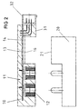
- FIG. 3 illustrates this on the valve block 20 by means of Screws 22 attached control unit 30.
- This is the thermally conductive Plate 16 directly connected to the valve block 20, to ensure good heat dissipation.
- valve coils 12 grouped into a block 34 before assembling the printed circuit board 10 will.
- plastic is attached to the coils 12 molded.
- This plastic forms a flexible connection 33 between the valve coils 12, so that the coils in X, Y and Z direction have some mobility to the assembly of the control unit 30 on the valve block 20 manufacturing tolerances of the valve block.
- the flexible Connection is shown as a curved plastic ribbon.
- the coil block 34 and the connector strip 32 are in the inserted a workpiece carrier printed circuit board 10.
- the previous solder paste printing also provides for the plated-through holes So much solder deposit available that soldering can be done reliably.
- the fully populated circuit board 10 is in a reflow oven soldered.
- the coils 12 or the connector strip 32 made of a plastic are suitable for the temperatures generated in the soldering furnace is how B. Polycarbonate terephthalate (PCT). After this The assembly can be completely checked by soldering.
- Figure 5 shows this on a fully assembled and soldered circuit board foamed housing 31 in a sectional view, before it is formed on the L-shaped shown in Figure 6 Valve block 20 is attached.
- the printed circuit board 10 forms an essentially flat surface, the area equipped with active electronic components 13 with the surface 21 of a projection of the valve block is thermally coupled.
- the circuit board also in direct contact with the surface of the valve block can be attached is a heat-conducting plate 16 between the valve block surface 21 and the conductor track carrier 10 provided. This makes it possible in principle to keep the contact surface 21 relatively narrow.
- the Stekker 32 is aligned parallel to the circuit board.
Landscapes
- Engineering & Computer Science (AREA)
- Physics & Mathematics (AREA)
- Electromagnetism (AREA)
- Manufacturing & Machinery (AREA)
- Microelectronics & Electronic Packaging (AREA)
- Fluid Mechanics (AREA)
- Transportation (AREA)
- Mechanical Engineering (AREA)
- Magnetically Actuated Valves (AREA)
- Regulating Braking Force (AREA)
Applications Claiming Priority (2)
| Application Number | Priority Date | Filing Date | Title |
|---|---|---|---|
| DE19704152 | 1997-02-04 | ||
| DE19704152A DE19704152C2 (de) | 1997-02-04 | 1997-02-04 | Steuergerät für ein Antiblockiersystem |
Publications (3)
| Publication Number | Publication Date |
|---|---|
| EP0856447A2 true EP0856447A2 (fr) | 1998-08-05 |
| EP0856447A3 EP0856447A3 (fr) | 1999-01-20 |
| EP0856447B1 EP0856447B1 (fr) | 2001-08-22 |
Family
ID=7819264
Family Applications (1)
| Application Number | Title | Priority Date | Filing Date |
|---|---|---|---|
| EP98100559A Expired - Lifetime EP0856447B1 (fr) | 1997-02-04 | 1998-01-14 | Appareil de commande pour un système de freinage antiblocage |
Country Status (3)
| Country | Link |
|---|---|
| US (1) | US6059382A (fr) |
| EP (1) | EP0856447B1 (fr) |
| DE (2) | DE19704152C2 (fr) |
Cited By (8)
| Publication number | Priority date | Publication date | Assignee | Title |
|---|---|---|---|---|
| EP0947408A3 (fr) * | 1998-03-30 | 2000-04-12 | Siemens Aktiengesellschaft | Appareil de commande pour une commande hydraulique de freinage et son procédé de fabrication |
| WO2001020955A1 (fr) * | 1999-09-13 | 2001-03-22 | Commergy Technologies Limited | Ensemble de carte de circuit imprime |
| EP1127764A2 (fr) * | 2000-02-26 | 2001-08-29 | WABCO GmbH & CO. OHG | Construction d'un modulateur de pression de freinage d'une remorque avec un système de freinage électronique |
| WO2006125732A1 (fr) * | 2005-05-24 | 2006-11-30 | Continental Teves Ag & Co. Ohg | Unite de reglage electronique a refroidissement par un bloc de distribution et de regulation |
| US7334848B2 (en) | 2003-09-17 | 2008-02-26 | Advics Co., Ltd. | Hydraulic pressure controller |
| WO2010029133A1 (fr) * | 2008-09-11 | 2010-03-18 | Continental Automotive Gmbh | Procédé de fabrication d’une unité de commande de soupape et unité de commande de soupape, amortisseur et véhicule automobile équipé de l’unité de commande de soupape |
| EP3015326A1 (fr) * | 2014-10-21 | 2016-05-04 | Nissin Kogyo Co., Ltd. | Dispositif de commande de véhicule et système de freinage de véhicule |
| WO2021170351A1 (fr) * | 2020-02-28 | 2021-09-02 | Knorr-Bremse Systeme für Nutzfahrzeuge GmbH | Carte de circuit imprimé avec un point de contact |
Families Citing this family (23)
| Publication number | Priority date | Publication date | Assignee | Title |
|---|---|---|---|---|
| DE19959632B4 (de) * | 1998-12-11 | 2009-11-26 | DENSO CORPORATION, Kariya-shi | Hydraulische Steuervorrichtung mit integrierter Motorantriebsschaltung |
| DE19921539B4 (de) * | 1999-05-11 | 2004-07-22 | Siemens Ag | Stecker für eine Kraftstoffpumpe eines Kraftfahrzeuges |
| WO2001017832A1 (fr) * | 1999-09-10 | 2001-03-15 | Kelsey-Hayes Company | Unite de commande electro-hydraulique pour systeme de commande de frein electrique |
| DE10026570B4 (de) | 2000-05-30 | 2013-11-21 | Conti Temic Microelectronic Gmbh | Ventilsteuergerät |
| DE10051884A1 (de) * | 2000-10-19 | 2002-04-25 | Cherry Gmbh | Verfahren zur Herstellung von Leiterfolie-Trägergehäuse-Einheiten |
| DE10104875A1 (de) | 2001-02-03 | 2002-08-08 | Bosch Gmbh Robert | Hydraulikaggregat für schlupfgeregelte Bremsanlagen von Kraftfahrzeugen sowie Verfahren zu dessen Herstellung |
| DE10120319B4 (de) * | 2001-04-26 | 2005-02-03 | Knorr-Bremse Systeme für Nutzfahrzeuge GmbH | Vorgesteuertes Ventil mit einem Druckausgleichskanal |
| US6485112B1 (en) | 2001-06-13 | 2002-11-26 | Trw Inc. | Assembly, with lead frame, for antilock brake system and associated method |
| US6842325B2 (en) * | 2001-09-19 | 2005-01-11 | Square D Company | Flexible circuit adhered to metal frame of device |
| US6825420B2 (en) * | 2002-01-12 | 2004-11-30 | Schefenacker Vision Systems Germany Gmbh & Co. Kg | Conductor of flexible material, component comprising such flexible conductor, and method of manufacturing such conductor |
| US7083311B2 (en) * | 2002-01-12 | 2006-08-01 | Schefenacker Vision Systems Germany Gmbh & Co. Kg | Conductor of flexible material, component comprising such flexible conductor, and method of manufacturing such conductor |
| DE10206271A1 (de) * | 2002-02-15 | 2003-08-28 | Conti Temic Microelectronic | Wärmeableitvorrichtung |
| JP3846437B2 (ja) * | 2003-03-17 | 2006-11-15 | 株式会社日立製作所 | 自動車用コントロールユニット |
| JP2006008107A (ja) * | 2004-05-26 | 2006-01-12 | Hitachi Ltd | 液圧制御装置及びその製造方法 |
| DE102005003132B8 (de) * | 2004-08-13 | 2010-07-22 | F.S. Fehrer Automotive Gmbh | Bauteil mit Hartschaumkörper und elektrischem und/oder elektronischem Funktionselement |
| TWI259748B (en) * | 2004-09-22 | 2006-08-01 | Murata Manufacturing Co | Wiring board and wiring board module |
| JP4520915B2 (ja) * | 2005-07-13 | 2010-08-11 | 日信工業株式会社 | 車両用ブレーキ液圧制御装置 |
| ATE526566T1 (de) * | 2005-08-01 | 2011-10-15 | Nexans | Anordnung zur lokalen überwachung von funktionen |
| DE102008026681B3 (de) * | 2008-06-04 | 2010-01-07 | Robert Bosch Gmbh | Einrichtung zur elektrischen Verbindung mehrerer als Ventileinheit angeordnete elektropneumatische Ventile |
| DE102008040157A1 (de) * | 2008-07-03 | 2010-01-07 | Robert Bosch Gmbh | Steuergerät für Personenschutzmittel für ein Fahrzeug bzw. Verfahren zum Zusammenbau eines solchen Steuergeräts |
| JP5193272B2 (ja) * | 2010-11-25 | 2013-05-08 | 日信工業株式会社 | 液圧制御装置およびその製造方法 |
| DE102014004213B3 (de) | 2014-03-24 | 2015-07-23 | Festo Ag & Co. Kg | Ventilanordnung |
| EP3340259B1 (fr) * | 2016-12-21 | 2019-09-25 | CPT Zwei GmbH | Dispositif à solénoïde |
Citations (2)
| Publication number | Priority date | Publication date | Assignee | Title |
|---|---|---|---|---|
| EP0499670B1 (fr) | 1991-02-20 | 1995-10-11 | Siemens Aktiengesellschaft | Dispositif de commande de valves |
| DE19518518C1 (de) | 1995-05-19 | 1996-08-29 | Siemens Ag | Steuergerät für ein Antiblockiersystem eines Kraftfahrzeugs |
Family Cites Families (3)
| Publication number | Priority date | Publication date | Assignee | Title |
|---|---|---|---|---|
| WO1992012878A1 (fr) * | 1991-01-15 | 1992-08-06 | Alfred Teves Gmbh | Regulateur electrohydraulique de pression |
| DE4225358A1 (de) * | 1992-07-31 | 1994-02-03 | Bosch Gmbh Robert | Anbausteuergerät |
| DE19518522C2 (de) * | 1995-05-19 | 1997-08-28 | Siemens Ag | Steuergerät für ein Kraftfahrzeug |
-
1997
- 1997-02-04 DE DE19704152A patent/DE19704152C2/de not_active Expired - Fee Related
-
1998
- 1998-01-14 DE DE59801233T patent/DE59801233D1/de not_active Expired - Lifetime
- 1998-01-14 EP EP98100559A patent/EP0856447B1/fr not_active Expired - Lifetime
- 1998-02-04 US US09/020,592 patent/US6059382A/en not_active Expired - Lifetime
Patent Citations (2)
| Publication number | Priority date | Publication date | Assignee | Title |
|---|---|---|---|---|
| EP0499670B1 (fr) | 1991-02-20 | 1995-10-11 | Siemens Aktiengesellschaft | Dispositif de commande de valves |
| DE19518518C1 (de) | 1995-05-19 | 1996-08-29 | Siemens Ag | Steuergerät für ein Antiblockiersystem eines Kraftfahrzeugs |
Cited By (13)
| Publication number | Priority date | Publication date | Assignee | Title |
|---|---|---|---|---|
| EP0947408A3 (fr) * | 1998-03-30 | 2000-04-12 | Siemens Aktiengesellschaft | Appareil de commande pour une commande hydraulique de freinage et son procédé de fabrication |
| WO2001020955A1 (fr) * | 1999-09-13 | 2001-03-22 | Commergy Technologies Limited | Ensemble de carte de circuit imprime |
| US6982876B1 (en) | 1999-09-13 | 2006-01-03 | Commergy Technologies Limited | Printed circuit board assembly |
| EP1127764A2 (fr) * | 2000-02-26 | 2001-08-29 | WABCO GmbH & CO. OHG | Construction d'un modulateur de pression de freinage d'une remorque avec un système de freinage électronique |
| EP1127764A3 (fr) * | 2000-02-26 | 2001-09-05 | WABCO GmbH & CO. OHG | Construction d'un modulateur de pression de freinage d'une remorque avec un système de freinage électronique |
| US6467854B2 (en) | 2000-02-26 | 2002-10-22 | Wabco Gmbh & Co., Ohg | Braking pressure modulator for a trailer with electronic braking system |
| DE102004044730B4 (de) * | 2003-09-17 | 2010-09-02 | Advics Co., Ltd., Kariya | Hydraulikdrucksteuergerät |
| US7334848B2 (en) | 2003-09-17 | 2008-02-26 | Advics Co., Ltd. | Hydraulic pressure controller |
| WO2006125732A1 (fr) * | 2005-05-24 | 2006-11-30 | Continental Teves Ag & Co. Ohg | Unite de reglage electronique a refroidissement par un bloc de distribution et de regulation |
| WO2010029133A1 (fr) * | 2008-09-11 | 2010-03-18 | Continental Automotive Gmbh | Procédé de fabrication d’une unité de commande de soupape et unité de commande de soupape, amortisseur et véhicule automobile équipé de l’unité de commande de soupape |
| EP3015326A1 (fr) * | 2014-10-21 | 2016-05-04 | Nissin Kogyo Co., Ltd. | Dispositif de commande de véhicule et système de freinage de véhicule |
| US10293802B2 (en) | 2014-10-21 | 2019-05-21 | Autollv Nissin Brake Systems Japan Co., Ltd. | Vehicle control device and vehicle brake system |
| WO2021170351A1 (fr) * | 2020-02-28 | 2021-09-02 | Knorr-Bremse Systeme für Nutzfahrzeuge GmbH | Carte de circuit imprimé avec un point de contact |
Also Published As
| Publication number | Publication date |
|---|---|
| DE19704152A1 (de) | 1998-08-06 |
| US6059382A (en) | 2000-05-09 |
| DE59801233D1 (de) | 2001-09-27 |
| EP0856447B1 (fr) | 2001-08-22 |
| DE19704152C2 (de) | 1998-11-05 |
| EP0856447A3 (fr) | 1999-01-20 |
Similar Documents
| Publication | Publication Date | Title |
|---|---|---|
| EP0856447B1 (fr) | Appareil de commande pour un système de freinage antiblocage | |
| DE19712842C1 (de) | Steuergerät für ein Kraftfahrzeug | |
| EP0588793B1 (fr) | Boitier pour composants electroniques d'automobile | |
| DE19955603C1 (de) | Steuergerät für ein Kraftfahrzeug und Herstellungsverfahren | |
| EP1208618B1 (fr) | Appareil de commande et procede de soudage | |
| EP0558712B1 (fr) | Dispositif electrique, notamment dispositif de commande et de commutation pour vehicules a moteur | |
| EP0708583A1 (fr) | Appareil électrique et sa fabrication | |
| DE19855389C2 (de) | Elektronische Vorrichtung | |
| WO2005025940A1 (fr) | Unite appareil de commande et son procede de production | |
| EP0446323B1 (fr) | Boitier pour circuits electroniques | |
| EP1459611A1 (fr) | Ensemble boitier pour un appareil electrique | |
| EP0872396B1 (fr) | Dispositif de commande de valves | |
| DE102007019095A1 (de) | Standardisiertes Trägerelement mit integrierter Schnittstelle | |
| WO2008049724A1 (fr) | Boîtier pour un appareil électronique de commande | |
| DE102007019098B4 (de) | Modul für eine integrierte Steuerelektronik mit vereinfachtem Aufbau | |
| DE102007039618B4 (de) | Modul für eine integrierte Steuerelektronik mit vereinfachtem Aufbau | |
| WO1996031103A1 (fr) | Carte de circuits imprimes | |
| DE19807718C2 (de) | Elektronikbaugruppe | |
| EP1057384B1 (fr) | Appareil de commande electronique | |
| DE19719238C1 (de) | Mit einer elektronischen Schaltung versehene Leiterplatte, auf deren erster Seite ein Steckerteil festgelegt ist und die mit einem elastisch verformbaren Folienleiter verbunden ist | |
| EP0744789A1 (fr) | Liaison électrique de composants situés à des endroits différents | |
| EP0854667A2 (fr) | Module de commande électronique | |
| DE102020100742A1 (de) | Leiterplatte, Lichtmodul, Beleuchtungseinrichtung und Kraftfahrzeug | |
| EP0947408A2 (fr) | Appareil de commande pour une commande hydraulique de freinage et son procédé de fabrication | |
| DE10246090A1 (de) | Elektronische Baugruppe für ein Kraftfahrzeug |
Legal Events
| Date | Code | Title | Description |
|---|---|---|---|
| PUAI | Public reference made under article 153(3) epc to a published international application that has entered the european phase |
Free format text: ORIGINAL CODE: 0009012 |
|
| AK | Designated contracting states |
Kind code of ref document: A2 Designated state(s): DE FR GB IT |
|
| AX | Request for extension of the european patent |
Free format text: AL;LT;LV;MK;RO;SI |
|
| PUAL | Search report despatched |
Free format text: ORIGINAL CODE: 0009013 |
|
| AK | Designated contracting states |
Kind code of ref document: A3 Designated state(s): AT BE CH DE DK ES FI FR GB GR IE IT LI LU MC NL PT SE |
|
| AX | Request for extension of the european patent |
Free format text: AL;LT;LV;MK;RO;SI |
|
| 17P | Request for examination filed |
Effective date: 19990219 |
|
| AKX | Designation fees paid |
Free format text: DE FR GB IT |
|
| 17Q | First examination report despatched |
Effective date: 20001016 |
|
| GRAG | Despatch of communication of intention to grant |
Free format text: ORIGINAL CODE: EPIDOS AGRA |
|
| GRAG | Despatch of communication of intention to grant |
Free format text: ORIGINAL CODE: EPIDOS AGRA |
|
| GRAH | Despatch of communication of intention to grant a patent |
Free format text: ORIGINAL CODE: EPIDOS IGRA |
|
| GRAH | Despatch of communication of intention to grant a patent |
Free format text: ORIGINAL CODE: EPIDOS IGRA |
|
| GRAA | (expected) grant |
Free format text: ORIGINAL CODE: 0009210 |
|
| AK | Designated contracting states |
Kind code of ref document: B1 Designated state(s): DE FR GB IT |
|
| REF | Corresponds to: |
Ref document number: 59801233 Country of ref document: DE Date of ref document: 20010927 |
|
| GBT | Gb: translation of ep patent filed (gb section 77(6)(a)/1977) |
Effective date: 20011117 |
|
| REG | Reference to a national code |
Ref country code: GB Ref legal event code: IF02 |
|
| ET | Fr: translation filed | ||
| PLBE | No opposition filed within time limit |
Free format text: ORIGINAL CODE: 0009261 |
|
| STAA | Information on the status of an ep patent application or granted ep patent |
Free format text: STATUS: NO OPPOSITION FILED WITHIN TIME LIMIT |
|
| 26N | No opposition filed | ||
| PGFP | Annual fee paid to national office [announced via postgrant information from national office to epo] |
Ref country code: GB Payment date: 20040113 Year of fee payment: 7 |
|
| PG25 | Lapsed in a contracting state [announced via postgrant information from national office to epo] |
Ref country code: IT Free format text: LAPSE BECAUSE OF NON-PAYMENT OF DUE FEES;WARNING: LAPSES OF ITALIAN PATENTS WITH EFFECTIVE DATE BEFORE 2007 MAY HAVE OCCURRED AT ANY TIME BEFORE 2007. THE CORRECT EFFECTIVE DATE MAY BE DIFFERENT FROM THE ONE RECORDED. Effective date: 20050114 Ref country code: GB Free format text: LAPSE BECAUSE OF NON-PAYMENT OF DUE FEES Effective date: 20050114 |
|
| GBPC | Gb: european patent ceased through non-payment of renewal fee |
Effective date: 20050114 |
|
| REG | Reference to a national code |
Ref country code: FR Ref legal event code: TP |
|
| PGFP | Annual fee paid to national office [announced via postgrant information from national office to epo] |
Ref country code: DE Payment date: 20130131 Year of fee payment: 16 Ref country code: FR Payment date: 20130213 Year of fee payment: 16 |
|
| REG | Reference to a national code |
Ref country code: DE Ref legal event code: R119 Ref document number: 59801233 Country of ref document: DE |
|
| PG25 | Lapsed in a contracting state [announced via postgrant information from national office to epo] |
Ref country code: DE Free format text: LAPSE BECAUSE OF NON-PAYMENT OF DUE FEES Effective date: 20140801 |
|
| REG | Reference to a national code |
Ref country code: FR Ref legal event code: ST Effective date: 20140930 |
|
| REG | Reference to a national code |
Ref country code: DE Ref legal event code: R119 Ref document number: 59801233 Country of ref document: DE Effective date: 20140801 |
|
| PG25 | Lapsed in a contracting state [announced via postgrant information from national office to epo] |
Ref country code: FR Free format text: LAPSE BECAUSE OF NON-PAYMENT OF DUE FEES Effective date: 20140131 |