US6842325B2 - Flexible circuit adhered to metal frame of device - Google Patents
Flexible circuit adhered to metal frame of device Download PDFInfo
- Publication number
- US6842325B2 US6842325B2 US09/955,660 US95566001A US6842325B2 US 6842325 B2 US6842325 B2 US 6842325B2 US 95566001 A US95566001 A US 95566001A US 6842325 B2 US6842325 B2 US 6842325B2
- Authority
- US
- United States
- Prior art keywords
- electrical
- electro
- housing
- accordance
- mechanical device
- Prior art date
- Legal status (The legal status is an assumption and is not a legal conclusion. Google has not performed a legal analysis and makes no representation as to the accuracy of the status listed.)
- Expired - Lifetime, expires
Links
Images


Classifications
-
- H—ELECTRICITY
- H05—ELECTRIC TECHNIQUES NOT OTHERWISE PROVIDED FOR
- H05K—PRINTED CIRCUITS; CASINGS OR CONSTRUCTIONAL DETAILS OF ELECTRIC APPARATUS; MANUFACTURE OF ASSEMBLAGES OF ELECTRICAL COMPONENTS
- H05K1/00—Printed circuits
- H05K1/18—Printed circuits structurally associated with non-printed electric components
- H05K1/189—Printed circuits structurally associated with non-printed electric components characterised by the use of a flexible or folded printed circuit
-
- H—ELECTRICITY
- H01—ELECTRIC ELEMENTS
- H01H—ELECTRIC SWITCHES; RELAYS; SELECTORS; EMERGENCY PROTECTIVE DEVICES
- H01H9/00—Details of switching devices, not covered by groups H01H1/00 - H01H7/00
- H01H9/52—Cooling of switch parts
-
- H—ELECTRICITY
- H01—ELECTRIC ELEMENTS
- H01H—ELECTRIC SWITCHES; RELAYS; SELECTORS; EMERGENCY PROTECTIVE DEVICES
- H01H50/00—Details of electromagnetic relays
- H01H50/12—Ventilating; Cooling; Heating
-
- H—ELECTRICITY
- H01—ELECTRIC ELEMENTS
- H01H—ELECTRIC SWITCHES; RELAYS; SELECTORS; EMERGENCY PROTECTIVE DEVICES
- H01H9/00—Details of switching devices, not covered by groups H01H1/00 - H01H7/00
- H01H9/02—Bases, casings, or covers
- H01H9/0271—Bases, casings, or covers structurally combining a switch and an electronic component
-
- H—ELECTRICITY
- H05—ELECTRIC TECHNIQUES NOT OTHERWISE PROVIDED FOR
- H05K—PRINTED CIRCUITS; CASINGS OR CONSTRUCTIONAL DETAILS OF ELECTRIC APPARATUS; MANUFACTURE OF ASSEMBLAGES OF ELECTRICAL COMPONENTS
- H05K1/00—Printed circuits
- H05K1/02—Details
- H05K1/0201—Thermal arrangements, e.g. for cooling, heating or preventing overheating
- H05K1/0203—Cooling of mounted components
Definitions
- the present invention relates generally to electrical circuit breakers, and, more specifically, to the assembly of electrical devices used in a circuit breaker by using flexible circuit boards.
- Electrical circuit breakers typically include devices such as actuators or a solenoids for effecting the movement of certain components in response to signals from one or more control circuits. These control circuits are typically mounted on rigid circuit boards that are mounted directly beside the devices being controlled, and are connected to those devices by wires. This arrangement can create problems when space becomes critical because space must be provided not only for the mounting of the circuit board but also to allow for the installation of the board and the wires that connect it to the device it is controlling. Accordingly, from this perspective the design of circuit breakers has met a design barrier when the object is to make a circuit breaker that is both small and economical.
- a principal object of the present invention to allow the placement of electronic components that are used to control a particular electrical device in an electrical circuit breaker, such as an actuator or a solenoid, directly onto the housing of that device without requiring a significant amount of additional space.
- Another object of the invention is to provide a more efficient heat dissipation environment for dissipating heat generated by the control circuitry, without having to add extra components such as, for example, a cooling fan.
- a related object is to reduce the dielectric separation between the electronic components and a heat sink.
- a circuit breaker that comprises a controllable electrical device that includes a housing formed of heat conductive material, and a flexible circuit board which is fastened directly to at least a portion of the housing.
- the flexible circuit board has a circuit printed on it, and at least one heat-generating electronic component is mounted on the flexible circuit board. Heat generated by the electrical component is transferred to the metal housing which functions as a heat sink from which heat is naturally dissipated to the surroundings.
- the flexible circuit board can be adhered to any portion of any surface of the housing, according to the design requirements, and connected directly to the device being controlled.
- the electrical apparatus is an electro-mechanical device.
- the combination of the flexible circuit board and at least one electrical component can comprise a control system for the electro-mechanical device, or a system that sends a control signal in response to a signal received from the electro-mechanical device, or it can transmit processed signals to a location outside the electrical device.
- the electro-mechanical device is a circuit breaker, a motor, a relay, a rheostat, a solenoid, an actuator, or a position sensor.
- the invention can be applied to control an under voltage release solenoid, to control a motor, to take readings from a position detector, to control any general solenoid, or to take readings from a temperature sensor that is on a pipe.
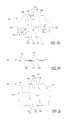
- FIG. 1 a is a side elevation view of an under voltage release embodying the invention
- FIG. 1 b is a top plan view of the under voltage release shown in FIG. 3 a;
- FIG. 1 c is a front elevation view of the under voltage release shown in FIG. 3 a;
- FIG. 2 a is a top plan view showing the exterior surface of the flexible circuit board included in the under voltage release shown in shown in FIGS. 1 a - 1 c;
- FIG. 2 b is a side elevation view of the flexible circuit board shown in FIG. 2 a;
- FIG. 2 c is a bottom plan view of the flexible circuit board shown in FIG. 2 a;
- FIG. 3 a is a rear elevation view of the metal C-frame included in the under voltage release shown in FIGS. 1 a - 1 c;
- FIG. 3 b is a top plan view of the metal C-frame shown in FIG. 3 a ;
- FIG. 3 c is a front elevation view of the metal C-frame shown in FIG. 3 a.
- an under voltage release 200 comprises a flexible circuit board 201 , a metal C-frame 202 , and a solenoid 203 .
- the flexible circuit board 201 has a first end section 204 and a second end section 205 that are mirror images of each other, being connected to each other by a joining section 206 (see FIG. 2 c ).
- the first end section 204 has a generally rectangular shape that approximately resembles the shape of a first frame surface 207 (see FIG. 3 a ).
- the second end section 205 has a generally rectangular shape that approximately resembles the shape of a second frame surface 208 (see FIG. 3 c ).
- the joining section 206 is rectangularly shaped, having a rectangular aperture 209 positioned near a lead wire end 210 , two lead wire holes 211 positioned near the lead wire end 210 , and two solenoid holes 212 positioned near a solenoid end 213 .
- a small bridge part 214 forms the part of the joining surface 206 that is towards the lead wire end 210 and a big bridge part 215 forms the part of the joining surface 206 that is towards the solenoid end 213 .
- the flexible circuit board 201 has an exterior surface 216 , on which a plurality of electronic components 217 are mounted, and an interior surface 218 .
- the interior surface 218 of the first end surface 204 and of the second end surface 205 is different than the interior surface 218 of the joining surface 206 .
- the flexible circuit board 201 is generally made of several layers of polyimide, adhesive, and RA copper that are sandwiched together having an adhesive backing as the last layer on the interior surface 218
- the interior surface 218 of the joining surface 206 has in addition a stiffener material to reinforce the joining surface 206 because the joining surface 206 does not have a corresponding mating surface to C-frame 202 .
- a small stiffener 219 and a big stiffener 220 are attached to the interior surface 218 of the joining surface 206 .
- the small stiffener 219 has a rectangular shape that is identical to the small bridge part 214 , including matching holes for the lead wire holes 211 .
- the big stiffener 220 has a rectangular shape that is identical to the big bridge part 215 , including matching holes for the solenoid holes 212 .
- Mounting the flexible circuit board 201 to the C-frame 202 requires that the joining surface 208 be placed over the C-frame 202 by having a pair of solenoid pins 221 , which are located next to the solenoid 203 , protrude through the solenoid holes 212 , and that the joining surface 208 is positioned in such a way that it mates with a board side 222 , which is located approximately next to the solenoid pins 221
- the flexible circuit board 201 is then secured to the C-frame 202 by soldering the solenoid pins 221 to the flexible circuit board 201 near the solenoid holes 212 .
- This provides a direct connection between the flexible circuit board 201 and the solenoid 203 , rather than an indirect connection through means such as wires, that saves space and allows the design of a smaller circuit breaker.
- the lead wires 223 are secured to the flexible circuit board 201 by soldering the lead wires 223 to the flexible circuit board 201 near the lead wire holes 211 .
- the first end surface 204 is wrapped around the C-frame 202 by mating the first end surface 204 to the first frame surface 207 and having the adhesive backing found on the interior surface 218 of the first end surface 204 adhere to the first frame surface 207 .
- the second end surface 205 is wrapped around the C-frame 202 by mating the second end surface 205 to the second frame surface 208 and having the adhesive backing found on the interior surface 218 of the second end surface 205 adhere to the second frame surface 208
- Adhering the flexible circuit board 201 directly onto the C-frame 202 eliminates dielectric separation between the electronic components 217 and the C-frame 202 . Additionally, because the C-frame 202 acts as a heat sink, the adhering of the flexible circuit board 201 onto the C-frame 202 allows improved dissipation of heat generated by the electronic components 217 .
- the flexible circuit board 201 is permanently mounted on the C-frame 202 and is directly connected to the solenoid 203 through the solenoid pins 221 , constituting the under voltage release 200 .
Abstract
Description
Claims (20)
Priority Applications (4)
| Application Number | Priority Date | Filing Date | Title |
|---|---|---|---|
| US09/955,660 US6842325B2 (en) | 2001-09-19 | 2001-09-19 | Flexible circuit adhered to metal frame of device |
| EP02354127A EP1296345B1 (en) | 2001-09-19 | 2002-09-02 | Flexible printed circuit adhered to metal frame |
| ES02354127T ES2366113T3 (en) | 2001-09-19 | 2002-09-02 | FLEXIBLE PRINTED CIRCUIT ADHERED TO A METALLIC STRUCTURE. |
| CNB021429561A CN100372040C (en) | 2001-09-19 | 2002-09-13 | Flexible circuit attached to metal frame of device |
Applications Claiming Priority (1)
| Application Number | Priority Date | Filing Date | Title |
|---|---|---|---|
| US09/955,660 US6842325B2 (en) | 2001-09-19 | 2001-09-19 | Flexible circuit adhered to metal frame of device |
Publications (2)
| Publication Number | Publication Date |
|---|---|
| US20030053279A1 US20030053279A1 (en) | 2003-03-20 |
| US6842325B2 true US6842325B2 (en) | 2005-01-11 |
Family
ID=25497157
Family Applications (1)
| Application Number | Title | Priority Date | Filing Date |
|---|---|---|---|
| US09/955,660 Expired - Lifetime US6842325B2 (en) | 2001-09-19 | 2001-09-19 | Flexible circuit adhered to metal frame of device |
Country Status (4)
| Country | Link |
|---|---|
| US (1) | US6842325B2 (en) |
| EP (1) | EP1296345B1 (en) |
| CN (1) | CN100372040C (en) |
| ES (1) | ES2366113T3 (en) |
Cited By (10)
| Publication number | Priority date | Publication date | Assignee | Title |
|---|---|---|---|---|
| US20060100045A1 (en) * | 2004-11-10 | 2006-05-11 | Shimano, Inc. | Apparatus for mounting a bicycle electrical component |
| US20060125583A1 (en) * | 2004-12-09 | 2006-06-15 | Eaton Corporation | Electrical switching apparatus including a housing and a trip circuit forming a composite structure |
| US20070232144A1 (en) * | 2006-03-29 | 2007-10-04 | Eaton Corporation | Shield, and printed circuit board and electrical apparatus employing the same |
| US20100149772A1 (en) * | 2008-12-16 | 2010-06-17 | Square D Company | Residential Circuit Breaker With Flexible Printed Circuit Boards |
| US20150342069A1 (en) * | 2014-05-20 | 2015-11-26 | Freescale Semiconductor, Inc. | Housing for electronic devices |
| US20160258984A1 (en) * | 2013-10-09 | 2016-09-08 | Schneider Electric USA, Inc. | Self-contained branch circuit monitor |
| US9885755B2 (en) | 2013-09-26 | 2018-02-06 | Schneider Electric USA, Inc. | Load center monitor with optical waveguide sheet |
| US10079619B2 (en) | 2013-11-26 | 2018-09-18 | Schneider Electric USA, Inc. | Wireless batteryless data processing unit |
| US10123436B2 (en) | 2014-03-31 | 2018-11-06 | Schneider Electric USA, Inc. | Live load indicator with door interlock |
| US10132692B2 (en) | 2013-12-06 | 2018-11-20 | Schneider Electric USA, Inc. | Temperature sensor for bolted connections |
Families Citing this family (8)
| Publication number | Priority date | Publication date | Assignee | Title |
|---|---|---|---|---|
| US11266014B2 (en) | 2008-02-14 | 2022-03-01 | Metrospec Technology, L.L.C. | LED lighting systems and method |
| US8851356B1 (en) * | 2008-02-14 | 2014-10-07 | Metrospec Technology, L.L.C. | Flexible circuit board interconnection and methods |
| US11424061B2 (en) | 2015-04-14 | 2022-08-23 | Hanchett Entry Systems, Inc. | Solenoid assembly actuation using resonant frequency current controller circuit |
| US10964467B2 (en) | 2015-04-14 | 2021-03-30 | Hanchett Entry Systems, Inc. | Solenoid assembly with included constant-current controller circuit |
| CN104966645B (en) * | 2015-06-09 | 2018-06-19 | 贵州振华群英电器有限公司(国营第八九一厂) | Improve the method and shell mechanism of intelligent relay performance |
| CN105764260A (en) * | 2016-05-04 | 2016-07-13 | 江苏深苏电子科技有限公司 | Method for printing integrated circuit on cell surface and cell shell prepared through method |
| CN109275323B (en) * | 2018-11-22 | 2021-12-17 | 努比亚技术有限公司 | Mobile terminal, heat dissipation method and device thereof, and flexible circuit board |
| GB2618463B (en) * | 2019-05-08 | 2024-03-06 | Hanchett Entry Systems Inc | Solenoid assembly with included constant-current controller circuit |
Citations (25)
| Publication number | Priority date | Publication date | Assignee | Title |
|---|---|---|---|---|
| DE2128633A1 (en) | 1971-06-09 | 1973-01-04 | Bbc Brown Boveri & Cie | SELF-SWITCH WITH MAGNETIC AND ELECTRODYNAMIC SHORT-CIRCUIT RELEASE |
| US4431877A (en) | 1982-03-01 | 1984-02-14 | General Electric Company | Thermal shield for circuit breaker operating spring |
| US4635011A (en) | 1985-05-01 | 1987-01-06 | Westinghouse Electric Corp. | Circuit breaker with arm latch for high interrupting capacity |
| US4644307A (en) | 1985-06-12 | 1987-02-17 | Kabushiki Kaisha Toshiba | Current limiting type circuit breaker |
| US4684183A (en) * | 1985-09-06 | 1987-08-04 | E. I. Du Pont De Nemours And Company | Connector for flexible printed circuit |
| US4716265A (en) | 1986-09-09 | 1987-12-29 | Mitsubishi Denki Kabushiki Kaisha | Circuit breaker with arc shielded contact arm |
| US4791393A (en) | 1983-12-19 | 1988-12-13 | Westinghouse Electric Corp. | Molded case circuit breaker with movable upper electrical contact positioned by torsion springs |
| US4841266A (en) | 1987-03-18 | 1989-06-20 | Licentia Patent-Verwaltungs-Gmbh | Circuit breaker having an electrodynamically opening contact system |
| JPH04280026A (en) | 1991-03-07 | 1992-10-06 | Fuji Electric Co Ltd | Circuit breaker |
| US5220488A (en) | 1985-09-04 | 1993-06-15 | Ufe Incorporated | Injection molded printed circuits |
| DE4404706A1 (en) | 1993-02-16 | 1994-09-08 | Fuji Electric Co Ltd | Moving contact-making device in a circuit breaker |
| US5440284A (en) | 1993-07-02 | 1995-08-08 | General Electric Company | Industrial-rated circuit breaker having universal application |
| US5528093A (en) * | 1993-03-31 | 1996-06-18 | Siemens Aktiengesellschaft | Commutator-motor gear/drive unit, in particular a window-lift drive for a motor vehicle |
| EP0772195A2 (en) | 1995-11-02 | 1997-05-07 | Fujitsu Limited | Carriage structure for a disk drive |
| JPH09161641A (en) | 1995-12-13 | 1997-06-20 | Mitsubishi Electric Corp | Circuit breaker |
| US5707249A (en) * | 1996-02-12 | 1998-01-13 | Schneider Automation Inc. | Device holder attaching to a printed circuit board |
| US5793270A (en) | 1996-09-03 | 1998-08-11 | Eaton Corporation | Circuit breaker with latch preventing rebound of blow open contact arm |
| US5834934A (en) * | 1995-08-14 | 1998-11-10 | Schneider Electric Sa | Inductive current sensor with reduced influence of spurious gaps and electrical apparatus including it |
| US5837950A (en) * | 1996-01-22 | 1998-11-17 | Terasaki Denki Sangyo Kabushiki Kaisha | Drawer type circuit breaker with drawer contacts biased against contact arcuate portions and external connection terminals |
| US5910760A (en) | 1997-05-28 | 1999-06-08 | Eaton Corporation | Circuit breaker with double rate spring |
| US5926081A (en) | 1997-09-23 | 1999-07-20 | Siemens Energy & Automation, Inc. | Circuit breaker having a cam structure which aids blow open operation |
| US5947753A (en) * | 1997-01-13 | 1999-09-07 | Amphenol Corporation | High density connector arrangement for a circuit board module |
| JP2000003655A (en) | 1998-06-15 | 2000-01-07 | Fuji Electric Co Ltd | Trip crossbar of circuit breaker |
| WO2001016986A1 (en) | 1999-08-27 | 2001-03-08 | Eaton Corporation | Circuit interrupter with improved welded contact interlock |
| US6341066B1 (en) * | 1999-09-30 | 2002-01-22 | Denso Corporation | Electronic control unit having drive element and control processing element |
Family Cites Families (8)
| Publication number | Priority date | Publication date | Assignee | Title |
|---|---|---|---|---|
| DE2124887C3 (en) * | 1971-05-19 | 1980-04-17 | Philips Patentverwaltung Gmbh, 2000 Hamburg | Electrical component, preferably semiconductor component, with foil contact |
| US4506198A (en) * | 1982-08-31 | 1985-03-19 | Eaton Corporation | Trigger speed control switch |
| US4858073A (en) * | 1986-12-10 | 1989-08-15 | Akzo America Inc. | Metal substrated printed circuit |
| US5103375A (en) * | 1990-02-05 | 1992-04-07 | Motorola, Inc. | Electronic module assembly and method of manufacture |
| MY124223A (en) * | 1991-09-12 | 2006-06-30 | Hitachi Global Storage Tech Netherlands B V | Disk drive apparatus. |
| DE4310705A1 (en) * | 1993-04-01 | 1994-10-06 | Bosch Gmbh Robert | Male connector strip for electronic controllers in motor vehicles |
| DE29617603U1 (en) * | 1996-10-08 | 1997-02-06 | Siemens Ag | Control device for a motor vehicle |
| DE19704152C2 (en) * | 1997-02-04 | 1998-11-05 | Siemens Ag | Control device for an anti-lock braking system |
-
2001
- 2001-09-19 US US09/955,660 patent/US6842325B2/en not_active Expired - Lifetime
-
2002
- 2002-09-02 ES ES02354127T patent/ES2366113T3/en not_active Expired - Lifetime
- 2002-09-02 EP EP02354127A patent/EP1296345B1/en not_active Expired - Lifetime
- 2002-09-13 CN CNB021429561A patent/CN100372040C/en not_active Expired - Lifetime
Patent Citations (25)
| Publication number | Priority date | Publication date | Assignee | Title |
|---|---|---|---|---|
| DE2128633A1 (en) | 1971-06-09 | 1973-01-04 | Bbc Brown Boveri & Cie | SELF-SWITCH WITH MAGNETIC AND ELECTRODYNAMIC SHORT-CIRCUIT RELEASE |
| US4431877A (en) | 1982-03-01 | 1984-02-14 | General Electric Company | Thermal shield for circuit breaker operating spring |
| US4791393A (en) | 1983-12-19 | 1988-12-13 | Westinghouse Electric Corp. | Molded case circuit breaker with movable upper electrical contact positioned by torsion springs |
| US4635011A (en) | 1985-05-01 | 1987-01-06 | Westinghouse Electric Corp. | Circuit breaker with arm latch for high interrupting capacity |
| US4644307A (en) | 1985-06-12 | 1987-02-17 | Kabushiki Kaisha Toshiba | Current limiting type circuit breaker |
| US5220488A (en) | 1985-09-04 | 1993-06-15 | Ufe Incorporated | Injection molded printed circuits |
| US4684183A (en) * | 1985-09-06 | 1987-08-04 | E. I. Du Pont De Nemours And Company | Connector for flexible printed circuit |
| US4716265A (en) | 1986-09-09 | 1987-12-29 | Mitsubishi Denki Kabushiki Kaisha | Circuit breaker with arc shielded contact arm |
| US4841266A (en) | 1987-03-18 | 1989-06-20 | Licentia Patent-Verwaltungs-Gmbh | Circuit breaker having an electrodynamically opening contact system |
| JPH04280026A (en) | 1991-03-07 | 1992-10-06 | Fuji Electric Co Ltd | Circuit breaker |
| DE4404706A1 (en) | 1993-02-16 | 1994-09-08 | Fuji Electric Co Ltd | Moving contact-making device in a circuit breaker |
| US5528093A (en) * | 1993-03-31 | 1996-06-18 | Siemens Aktiengesellschaft | Commutator-motor gear/drive unit, in particular a window-lift drive for a motor vehicle |
| US5440284A (en) | 1993-07-02 | 1995-08-08 | General Electric Company | Industrial-rated circuit breaker having universal application |
| US5834934A (en) * | 1995-08-14 | 1998-11-10 | Schneider Electric Sa | Inductive current sensor with reduced influence of spurious gaps and electrical apparatus including it |
| EP0772195A2 (en) | 1995-11-02 | 1997-05-07 | Fujitsu Limited | Carriage structure for a disk drive |
| JPH09161641A (en) | 1995-12-13 | 1997-06-20 | Mitsubishi Electric Corp | Circuit breaker |
| US5837950A (en) * | 1996-01-22 | 1998-11-17 | Terasaki Denki Sangyo Kabushiki Kaisha | Drawer type circuit breaker with drawer contacts biased against contact arcuate portions and external connection terminals |
| US5707249A (en) * | 1996-02-12 | 1998-01-13 | Schneider Automation Inc. | Device holder attaching to a printed circuit board |
| US5793270A (en) | 1996-09-03 | 1998-08-11 | Eaton Corporation | Circuit breaker with latch preventing rebound of blow open contact arm |
| US5947753A (en) * | 1997-01-13 | 1999-09-07 | Amphenol Corporation | High density connector arrangement for a circuit board module |
| US5910760A (en) | 1997-05-28 | 1999-06-08 | Eaton Corporation | Circuit breaker with double rate spring |
| US5926081A (en) | 1997-09-23 | 1999-07-20 | Siemens Energy & Automation, Inc. | Circuit breaker having a cam structure which aids blow open operation |
| JP2000003655A (en) | 1998-06-15 | 2000-01-07 | Fuji Electric Co Ltd | Trip crossbar of circuit breaker |
| WO2001016986A1 (en) | 1999-08-27 | 2001-03-08 | Eaton Corporation | Circuit interrupter with improved welded contact interlock |
| US6341066B1 (en) * | 1999-09-30 | 2002-01-22 | Denso Corporation | Electronic control unit having drive element and control processing element |
Non-Patent Citations (12)
| Title |
|---|
| Description of Fuji Circuit Breaker-F-9-11, as early as 1995, 2 pages. |
| Description of Mitsubishi Circuit Breaker-M-21-6, as early as 1995, 2 pages. |
| Description of Terasaki Circuit Breaker-Te21-43, as early as 1995, 1 page. |
| Description of Toshiba Circuit Breaker-T-9-2, as early as 1995, 1 page. |
| Patent Abstract for Germany-DE 4404706 A, 1 page. (see B03). |
| Patent Abstract for Japan-JP 9161641 A, 1 page. (see B05). |
| Patent Abstracts for Japan-Publ. No. 04-280026, Oct. 6, 1992, 1 page. (see B04). |
| Patent Abstracts for Japan-Publ. No. 2000-003655, Jan. 7, 2000, 1 page. (see B06). |
| Photographs of Fuji Circuit Breaker-F-9-11, Photographs 12-29, 18 pages. |
| Photographs of Mitsubishi Circuit Breaker-M-21-6, Photographs 30-48, 19 pages. |
| Photographs of Terasaki Circuit Breaker-Te21-43, Photographs 1-11, 11 pages. |
| Photographs of Toshiba Circuit Breaker-T-9-2, Photographs 49-61, 13 pages. |
Cited By (15)
| Publication number | Priority date | Publication date | Assignee | Title |
|---|---|---|---|---|
| US7980974B2 (en) | 2004-11-10 | 2011-07-19 | Shimano, Inc. | Apparatus for mounting a bicycle electrical component |
| US20060100045A1 (en) * | 2004-11-10 | 2006-05-11 | Shimano, Inc. | Apparatus for mounting a bicycle electrical component |
| US20060125583A1 (en) * | 2004-12-09 | 2006-06-15 | Eaton Corporation | Electrical switching apparatus including a housing and a trip circuit forming a composite structure |
| US7170376B2 (en) * | 2004-12-09 | 2007-01-30 | Eaton Corporation | Electrical switching apparatus including a housing and a trip circuit forming a composite structure |
| US20070232144A1 (en) * | 2006-03-29 | 2007-10-04 | Eaton Corporation | Shield, and printed circuit board and electrical apparatus employing the same |
| US7358836B2 (en) | 2006-03-29 | 2008-04-15 | Eaton Corporation | Shield, and printed circuit board and electrical apparatus employing the same |
| US20100149772A1 (en) * | 2008-12-16 | 2010-06-17 | Square D Company | Residential Circuit Breaker With Flexible Printed Circuit Boards |
| US8971055B2 (en) | 2008-12-16 | 2015-03-03 | Schneider Electric USA, Inc. | Residential circuit breaker with flexible printed circuit boards |
| US9885755B2 (en) | 2013-09-26 | 2018-02-06 | Schneider Electric USA, Inc. | Load center monitor with optical waveguide sheet |
| US20160258984A1 (en) * | 2013-10-09 | 2016-09-08 | Schneider Electric USA, Inc. | Self-contained branch circuit monitor |
| US9964567B2 (en) * | 2013-10-09 | 2018-05-08 | Schneider Electric USA, Inc. | Self-contained branch circuit monitor |
| US10079619B2 (en) | 2013-11-26 | 2018-09-18 | Schneider Electric USA, Inc. | Wireless batteryless data processing unit |
| US10132692B2 (en) | 2013-12-06 | 2018-11-20 | Schneider Electric USA, Inc. | Temperature sensor for bolted connections |
| US10123436B2 (en) | 2014-03-31 | 2018-11-06 | Schneider Electric USA, Inc. | Live load indicator with door interlock |
| US20150342069A1 (en) * | 2014-05-20 | 2015-11-26 | Freescale Semiconductor, Inc. | Housing for electronic devices |
Also Published As
| Publication number | Publication date |
|---|---|
| ES2366113T3 (en) | 2011-10-17 |
| CN100372040C (en) | 2008-02-27 |
| EP1296345A3 (en) | 2005-02-09 |
| EP1296345A2 (en) | 2003-03-26 |
| CN1409343A (en) | 2003-04-09 |
| US20030053279A1 (en) | 2003-03-20 |
| EP1296345B1 (en) | 2011-06-01 |
Similar Documents
| Publication | Publication Date | Title |
|---|---|---|
| US6842325B2 (en) | Flexible circuit adhered to metal frame of device | |
| US5459639A (en) | Printed circuit board assembly having high heat radiation property | |
| JP4844883B2 (en) | Electronic device and printed circuit board GND connection method | |
| KR100292417B1 (en) | Switching and control machines for cars | |
| JPH09223820A (en) | Display apparatus | |
| JP2011108924A (en) | Heat conducting substrate and method for mounting electronic component on the same | |
| JP2002134970A (en) | Electronic controller | |
| US20200214167A1 (en) | Heat dissipation structure and heat dissipation method of electronic device | |
| KR20170082931A (en) | Printed circuit board and camera module having the same | |
| JP4089300B2 (en) | Substrate storage box | |
| JP2002171087A (en) | Electronic equipment | |
| JP2005191378A (en) | Heat radiation structure in printed board | |
| JP2003143451A (en) | Solid-state image pickup device | |
| JP5013846B2 (en) | Relay module | |
| JPH0322554A (en) | Heat dissipation device for electronic component | |
| JP2001230580A (en) | Electronic apparatus with module board | |
| JP2601580B2 (en) | Flexible printed circuit board double-sided mounting method | |
| JP2539192B2 (en) | Display device | |
| JP2007019426A (en) | Electronic apparatus | |
| KR20080004734A (en) | Radiating structure in exothermic element | |
| KR200256593Y1 (en) | Structure for heat sink of the power device | |
| JP2906677B2 (en) | Integrated circuit package | |
| JP2007013144A (en) | System, method, and device for routing signal from integrated circuit by utilizing thick film and printed circuit interconnection | |
| JP2001257490A (en) | Heat dissipating structure for electronic apparatus | |
| JP2006179763A (en) | Electronic device |
Legal Events
| Date | Code | Title | Description |
|---|---|---|---|
| AS | Assignment |
Owner name: SQUARE D COMPANY, ILLINOIS Free format text: INVALID ASSIGNMENT;ASSIGNORS:MEEHLEDER, STEVEN M.;GRATTAN, BRIAN;REEL/FRAME:012492/0452;SIGNING DATES FROM 20010928 TO 20011001 |
|
| AS | Assignment |
Owner name: SCHNEIDER ELECTRIC INDUSTRIES, SA, ILLINOIS Free format text: ASSIGNMENT OF ASSIGNORS INTEREST;ASSIGNOR:SQUARE D COMPANY;REEL/FRAME:013012/0784 Effective date: 20020322 |
|
| AS | Assignment |
Owner name: SCHNEIDER ELECTRIC INDUSTRIES, SA, ILLINOIS Free format text: (ASSIGNMENT OF ASSIGNOR'S INTEREST) RE-RECORD TO ADD PATENT NUMBERS THAT WERE OMITTED ON REEL 012492 FRAME 0452;ASSIGNOR:SQUARE D COMPANY;REEL/FRAME:013186/0166 Effective date: 20020322 |
|
| STCF | Information on status: patent grant |
Free format text: PATENTED CASE |
|
| REMI | Maintenance fee reminder mailed | ||
| FPAY | Fee payment |
Year of fee payment: 4 |
|
| SULP | Surcharge for late payment | ||
| AS | Assignment |
Owner name: SCHNEIDER ELECTRIC INDUSTRIES SAS, FRANCE Free format text: CHANGE OF NAME;ASSIGNOR:SCHNEIDER ELECTRIC INDUSTRIES SA;REEL/FRAME:021523/0656 Effective date: 20020522 Owner name: SCHNEIDER ELECTRIC JAPAN LTD., JAPAN Free format text: ASSIGNMENT OF ASSIGNORS INTEREST;ASSIGNOR:SCHNEIDER ELECTRIC INDUSTRIES SAS;REEL/FRAME:021523/0271 Effective date: 20080828 |
|
| FPAY | Fee payment |
Year of fee payment: 8 |
|
| FPAY | Fee payment |
Year of fee payment: 12 |