EP0856437B1 - Gehäuse für den Gassack in einem Kraftfahrzeug - Google Patents
Gehäuse für den Gassack in einem Kraftfahrzeug Download PDFInfo
- Publication number
- EP0856437B1 EP0856437B1 EP97122219A EP97122219A EP0856437B1 EP 0856437 B1 EP0856437 B1 EP 0856437B1 EP 97122219 A EP97122219 A EP 97122219A EP 97122219 A EP97122219 A EP 97122219A EP 0856437 B1 EP0856437 B1 EP 0856437B1
- Authority
- EP
- European Patent Office
- Prior art keywords
- housing
- chamber
- gas generator
- diffuser
- motor vehicle
- Prior art date
- Legal status (The legal status is an assumption and is not a legal conclusion. Google has not performed a legal analysis and makes no representation as to the accuracy of the status listed.)
- Expired - Lifetime
Links
- 229920003023 plastic Polymers 0.000 claims description 9
- 239000004033 plastic Substances 0.000 claims description 9
- 230000003014 reinforcing effect Effects 0.000 claims description 8
- 229910052782 aluminium Inorganic materials 0.000 claims description 3
- XAGFODPZIPBFFR-UHFFFAOYSA-N aluminium Chemical compound [Al] XAGFODPZIPBFFR-UHFFFAOYSA-N 0.000 claims description 3
- 239000004411 aluminium Substances 0.000 claims 1
- 238000007789 sealing Methods 0.000 description 4
- 230000000295 complement effect Effects 0.000 description 3
- 238000004519 manufacturing process Methods 0.000 description 3
- 238000000034 method Methods 0.000 description 3
- 230000008569 process Effects 0.000 description 3
- 241000251468 Actinopterygii Species 0.000 description 2
- 238000010276 construction Methods 0.000 description 2
- 230000000694 effects Effects 0.000 description 2
- 238000002347 injection Methods 0.000 description 2
- 239000007924 injection Substances 0.000 description 2
- 239000000463 material Substances 0.000 description 2
- 229910052751 metal Inorganic materials 0.000 description 2
- 239000002184 metal Substances 0.000 description 2
- 238000004064 recycling Methods 0.000 description 2
- 239000000243 solution Substances 0.000 description 2
- 238000009827 uniform distribution Methods 0.000 description 2
- AZDRQVAHHNSJOQ-UHFFFAOYSA-N alumane Chemical group [AlH3] AZDRQVAHHNSJOQ-UHFFFAOYSA-N 0.000 description 1
- 230000008901 benefit Effects 0.000 description 1
- 238000004512 die casting Methods 0.000 description 1
- 238000005516 engineering process Methods 0.000 description 1
- 230000006872 improvement Effects 0.000 description 1
- 238000001746 injection moulding Methods 0.000 description 1
- 238000009434 installation Methods 0.000 description 1
- 238000002844 melting Methods 0.000 description 1
- 230000008018 melting Effects 0.000 description 1
- 239000007769 metal material Substances 0.000 description 1
- 238000003892 spreading Methods 0.000 description 1
- 230000007480 spreading Effects 0.000 description 1
- 230000001960 triggered effect Effects 0.000 description 1
- 239000013585 weight reducing agent Substances 0.000 description 1
Images

Classifications
-
- B—PERFORMING OPERATIONS; TRANSPORTING
- B60—VEHICLES IN GENERAL
- B60R—VEHICLES, VEHICLE FITTINGS, OR VEHICLE PARTS, NOT OTHERWISE PROVIDED FOR
- B60R21/00—Arrangements or fittings on vehicles for protecting or preventing injuries to occupants or pedestrians in case of accidents or other traffic risks
- B60R21/02—Occupant safety arrangements or fittings, e.g. crash pads
- B60R21/16—Inflatable occupant restraints or confinements designed to inflate upon impact or impending impact, e.g. air bags
- B60R21/20—Arrangements for storing inflatable members in their non-use or deflated condition; Arrangement or mounting of air bag modules or components
- B60R21/217—Inflation fluid source retainers, e.g. reaction canisters; Connection of bags, covers, diffusers or inflation fluid sources therewith or together
- B60R21/2171—Inflation fluid source retainers, e.g. reaction canisters; Connection of bags, covers, diffusers or inflation fluid sources therewith or together specially adapted for elongated cylindrical or bottle-like inflators with a symmetry axis perpendicular to the main direction of bag deployment, e.g. extruded reaction canisters
Definitions
- the invention relates to a housing for an inflatable gas bag in one Motor vehicle according to the preamble of claim 1.
- a Housing can be considered known, see GB-A-2 268 714.
- Inflatable gas bags or airbags are increasingly used in modern automobile construction.
- the gas bag is housed together with an inflator in a housing.
- the inflator is also referred to as a gas generator.
- the system is ignited by sensors.
- Housings for inflatable gas bags in a wide variety of variants are known.
- DE 41 41 617 A1 shows a vehicle gas bag module in which a folded gas bag and an inflator are housed together in one housing and are used as a complete structural unit in the vehicle.
- the housing has two compartments, a front compartment and a rear compartment.
- An inflator is inserted in the rear compartment. This consists of a cylindrical, outer housing in which a large number of nozzles are formed.
- the cylindrical outer housing is called a diffuser.
- the diffuser is used to hold the gas generator.
- the bores of the diffuser are arranged in the housing of the gas bag unit in such a way that the gas can flow out into the gas bag in a directed manner. Without a diffuser, the gas would spread unevenly after the gas generator ignited. This would not be desirable since the gas bag must be inflated safely, reliably and evenly in a fraction of a second in order to function properly.
- the diffuser with the gas generator inserted therein is inserted into a receptacle in one side wall of the housing and screwed to the opposite housing wall via a threaded shaft.
- the entire housing construction is composed of several individual parts in the embodiment shown in this document.
- the housing itself is manufactured as a sheet metal part to which a sheet metal part, acting as a reinforcing rib, is welded. Alternatively, the rib is glued to a plastic housing. In addition to the complex manufacturing technology, such a housing has a high weight.
- the invention is based on the technical problem of a housing for the to develop inflatable gas bag in a motor vehicle that is easier and is cheaper to produce than known designs.
- a housing according to the invention is together with those molded onto it Brackets and the diffuser receiving the gas generator made in one piece.
- Plastic offers itself as a material because it is easy to process and a high weight reduction compared to metallic designs.
- connector fasteners, cable holders or others required components to be made in one piece with the housing, so that this in Injection molding process can be produced in one operation and additional components are not more have to be manufactured and assembled.
- the housing can also be made from an Aluminum die-casting process manufactured aluminum exist.
- the housing which consists of two chambers, has a front chamber for receiving the folded gas bag or gas bag module and a rear chamber for installing the gas generator.
- the rear chamber is designed as a diffuser. Reinforcing ribs are provided on the outer wall of this diffuser chamber for the folded gas bag to rest. The reinforcing ribs on the one hand stabilize the housing and on the other hand ensure a distance between the gas bag module and the rear chamber of the housing.
- the flow-optimized gas passage openings are introduced between the reinforcing ribs and are designed both with regard to their cross-sectional design and their arrangement such that the gas bag is inflated uniformly.
- the diffuser chamber is preferably closed on one side except for a fastening opening.
- the opening for inserting the gas generator is on the opposite side.
- This opening is reinforced in its edge area and should also have a contact area that can be used as a seal. This could, for example, be designed as a labyrinth.
- the gas generator inserted into this opening has a circumferential radial flange which is shaped to complement the contact area. This is enclosed by a seal that is fitted into the contact area of the diffuser chamber wall when the gas generator is installed.
- the gas generator is installed in a very simple manner, for example by means of a screw connection. Of course, it is also possible to lock the gas generator in the diffuser chamber by means of a snap connection or in another way.
- the gas generator is on the radial flange opposite side, a screw bolt attached on one side, which in the Fastening opening of the diffuser chamber is inserted and penetrates it.
- a sealing element is additionally provided on the screw connection side of the gas generator become.
- a sealing effect can of course also be achieved in that the the bolts attached to the gas generator in some areas complementary shaped receptacle engages in the mounting opening.
- the gas generator is made smaller than the diffuser chamber that receives it.
- an air gap remains around the gas generator, which enables the flow-optimized and uniform distribution of the gas which spreads after ignition before it exits through the gas passage openings into the gas bag.
- the air gap can also prevent the ignited gas generator from melting into the housing.
- a multi-walled version is particularly efficient if more than two separate, parallel chamber systems the outer wall of the chamber form. Immediately after the airbag is triggered occur in the area of Airbag outlet extremely large forces that the fish mouth like after expand outside. The largest expansion takes place approximately in the middle in the area of the free opening of the chamber. Through this fish mouth-like expansion of the housing Damage to the surrounding components can occur, which can be avoided.
- a further improvement in the housing rigidity can be found in addition to the multi-walled one Execution of the chamber wall in particular can also be achieved by the gas bag receiving chamber wall is additionally provided with stiffening ribs on the outside. These stiffening ribs are only effective if they are of the weakest Starting point of the chamber wall, for example, star-shaped or run in a circular arc. The weakest point of the chamber wall is located centered on the front of the chamber opening, as the chamber wall is against can make the greatest free journeys here. Honeycomb structures too have seen each other in the top view compared to the previously known rectangular contours better proven. With structuring and at the same time Multi-walled design of the chamber wall can be known Versions the wall thickness can be reduced with improved strength.
- a housing according to the invention for an inflatable airbag in a motor vehicle the better adaptability to the installation environment and the resulting simplified assembly are advantageous.
- a housing according to the invention is also easy to disassemble and is better suited to increased recycling requirements than previously known designs.
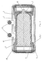
- FIG. 1 shows a three-dimensional representation of a housing (1) according to the invention for an inflatable airbag in a motor vehicle.
- a housing (1) is made in one piece together with the brackets (3) formed thereon and the diffuser (2) accommodating the gas generator (4). It is made of plastic and is injection molded.
- the housing (1) which consists of two chambers, has a front chamber (1.1) for receiving the folded gas bag or gas bag module and a rear chamber (2) for installing the gas generator (4).
- the rear chamber (2) is designed as a diffuser. Reinforcing ribs (5) for fitting the folded gas bag are formed on the outer wall of this diffuser chamber (2).
- the reinforcing ribs (5) on the one hand stabilize the housing (1) and on the other hand ensure a distance between the gas bag module and the diffuser chamber (2) of the housing.
- the gas passage openings (6) are introduced between the reinforcing ribs (5).
- the diffuser chamber (2) is closed on one side except for a fastening opening (7).
- On the opposite side there is an opening for inserting the gas generator (4).
- the gas generator (4) not shown in FIG. 1, is pushed into the diffuser chamber (2) in the direction of the arrow labeled A.
- the opening has a reinforced edge area (8) which is provided on the inside with a contact area designed as a labyrinth seal.
- FIG. 2 shows a three-dimensional representation of a housing (1) according to the invention for an inflatable airbag in a motor vehicle with a partial section through the diffuser chamber (2).
- the diffuser chamber (2) has an opening on one side, the edge region (8) of which is reinforced.
- the edge area (8) also has a contact area (8.1).
- the gas generator (4) inserted into the opening is provided on one side with a radial flange (9) which is complementary to the contact area (8.1). This radial flange (9) is enclosed by a seal (10) which is fitted into the contact area (8.1) of the diffuser chamber wall when the gas generator (4) is installed.
- the gas generator (4) is assembled in a very simple manner by means of a screw connection.
- a screw bolt (11) is fastened on one side to the gas generator (4) and is inserted into the fastening opening (7) of the diffuser chamber (2) and penetrates it. From the free outer side of the housing, the gas generator (4) is then aretted in a manner known per se by means of a nut (not shown in FIG. 2). To improve the sealing effect, the screw bolt (11) attached to the gas generator engages in regions in a complementarily shaped receptacle in the fastening opening (7). By tightening the screw connection, the seal (10) between the radial flange (9) of the gas generator (4) and the contact area (8.1) of the diffuser chamber wall also becomes effective. According to the invention, the gas generator (4) is made smaller than the diffuser chamber (2) receiving it.
- an air gap (12) remains between the gas generator (4) and the diffuser chamber wall (2), which enables the gas which has a flow-optimized and uniform distribution after the ignition to pass before it passes through the gas passage openings (6), which are not shown in Figure 2, exits into the gas bag.
- the brackets (3) are integrally formed on the housing (1) in a manner known per se and are made in one piece therewith.
Landscapes
- Engineering & Computer Science (AREA)
- Mechanical Engineering (AREA)
- Air Bags (AREA)
Description
Der Diffusor mit dem darin eingesetzten Gasgenerator wird in eine Aufnahme in der einen Seitenwand des Gehäuses eingeführt und über einen Gewindeschaft mit der gegenüberliegenden Gehäusewand verschraubt.
Die gesamte Gehäusekonstruktion ist bei der in dieser Schrift gezeigten Ausführung aus mehreren Einzelteilen zusammengesetzt. Das Gehäuse selbst ist als Blechteil hergestellt, an das ein Blechteil, wirkend als eine Verstärkungsrippe, angeschweißt ist. Bei einem Kunststoffgehäuse ist alternativ die Rippe angeklebt. Neben der fertigungstechnisch aufwendigen Herstellung hat ein derartiges Gehäuse ein hohes Eigengewicht.
Die Diffusorkammer ist vorzugsweise bis auf eine Befestigungsöffnung einseitig geschlossen. Auf der gegenüberliegenden Seite befindet sich die Öffnung zum Einführen des Gasgenerators. Diese Öffnung ist in ihrem Randbereich verstärkt ausgeführt und sollte darüber hinaus einen als Dichtung verwendbaren Anlagebereich aufweisen. Dieser könnte beispielsweise als Labyrinth ausgeführt sein. Der in diese Öffnung eingeführte Gasgenerator weist einen komplementär zu dem Anlagebereich geformten, umlaufenden Radialflansch auf. Dieser wird von einer Dichtung umschlossen, die bei der Montage des Gasgenerators in den Anlagebereich der Diffusorkammerwandung eingepaßt wird. Die Montage des Gasgenerators erfolgt auf sehr einfache Weise beispielsweise durch eine Schraubverbindung. Selbstverständlich ist es auch möglich, den Gasgenerator mittels einer Schnappverbindung oder in anderer Weise in der Diffusorkammer zu arettieren.
Darüber hinaus kann der Luftspalt auch ein Verschmelzen des gezündeten Gasgenerators mit dem Gehäuse verhindern. Erfahrungsgemäß entwickeln sich nämlich je nach Gasgeneratorausführung unmittelbar nach der Zündung desselben, extrem hohe Temperaturen. Der Luftspalt verhindert mithin eine Verschmelzung von Gasgenerator und Kunststoffgehäuse, dessen Recycling nach dem Verschmelzen des Gasgenerators mit dem Gehäuse nahezu ausgeschlossen wäre.
Nicht zuletzt ist ein erfindungsgemäßes Gehäuse auch einfach zu demontieren und wird gestiegenen Recyclinganforderungen besser gerecht, als bisher bekannte Ausführungen.
und
Das aus zwei Kammern bestehende Gehäuse (1) weist eine vordere Kammer (1.1) zur Aufnahme des gefalteten Gassacks oder Gasackmoduls und eine hintere Kammer (2) zum Einbau des Gasgenerators (4) auf. Die hintere Kammer (2) ist als Diffusor ausgeführt. An der äußeren Wandung dieser Diffusorkammer (2) sind Verstärkungsrippen (5) zur Anlage des gefalteten Gassackes angeformt. Die Verstärkungsrippen (5) stabilisieren einerseits das Gehäuse (1) und gewährleisten andererseits einen Abstand zwischen dem Gassackmodul und der Diffusorkammer (2) des Gehäuses. Zwischen den Verstärkungsrippen (5) sind die Gasdurchlassöffnungen (6) eingebracht. Die Diffusorkammer (2) ist bis auf eine Befestigungsöffnung (7) einseitig geschlossen. Auf der gegenüberliegenden Seite befindet sich eine Öffnung zum Einführen des Gasgenerators (4). Der in der Figur 1 nicht dargestellte Gasgenerator (4) wird in Richtung des mit A bezeichneten Pfeiles in die Diffusorkammer (2) eingeschoben. Die Öffnung weist einen verstärkten Randbereich (8) auf, der innen mit einem als Labyrinthdichtung ausgeführten Anlagebereich versehen ist.
Die Diffusorkammer (2) weist dabei einseitig eine Öffnung auf, deren Randbereich (8) verstärkt ausgeführt ist. Der Randbereich (8) weist darüber hinaus einen Anlagebereich (8.1) auf.
Der in die Öffnung eingeführte Gasgenerator (4) ist einseitig mit einem komplementär zu dem Anlagebereich (8.1) geformten Radialflansch (9) ausgestattet. Dieser Radialflansch (9) wird von einer Dichtung (10) umschlossen, die bei der Montage des Gasgenerators (4) in den Anlagebereich (8.1) der Diffusorkammerwandung eingepaßt wird. Die Montage des Gasgenerators (4) erfolgt auf sehr einfache Weise durch eine Schraubverbindung. An dem Gasgenerator (4) ist einseitig ein Schraubbolzen (11) befestigt, der in die Befestigungsöffnung (7) der Diffusorkammer (2) eingeführt wird und diese durchdringt. Von der freien äußeren Seite des Gehäuses her wird der Gasgenerator (4) dann mittels einer in der Figur 2 nicht dargestellten Mutter in an sich bekannter Weise arettiert. Um die Dichtwirkung zu verbessern, greift der an dem Gasgenerator angebrachte Schraubbolzen (11) bereichsweise in eine komplementär geformte Aufnahme in der Befestigungsöffnung (7) ein.
Durch das Festziehen der Verschraubung wird auch die Dichtung (10) zwischen dem Radialflansch (9) des Gasgenerators (4) und dem Anlagebereich (8.1) der Diffusorkammerwandung wirksam.
Der Gasgenerator (4) ist erfindungsgemäß kleiner ausgeführt, als die ihn aufnehmende Diffusorkammer (2). Somit verbleibt nach dem Einbau des Gasgenerators in der Diffusorkammer ein Luftspalt (12) zwischen Gasgenerator (4) und Diffusorkammerwandung (2), der die strömungsoptimierte und gleichmäßige Verteilung des nach der Zündung sich ausbreitenden Gases ermöglicht, bevor dieses durch die Gasdurchlassöffnungen (6), die in der Figur 2 nicht dargestellt sind, in den Gassack austritt.
Die Halterungen (3) sind in an sich bekannter Weise an dem Gehäuse (1) angeformt und mit diesem einstückig ausgeführt.
Claims (4)
- Gehäuse für einen aufblasbaren Gassack in einem Kraftfahrzeug in einteiliger Ausführung, mit daran angeformten Befestigungshalterungen (3), mit einer Diffusorkammer (2), in der ein Gasgenerator eingesetzt ist, und mit einer Kammer (1,1) zur Aufnahme eines gefalteten Gassackes, wobei die Diffusorkammerwandung zwischen den beiden Kammern des Gehäuses (1) mit strömungsoptimierten Gasdurchlassöffnungen (6) ausgestattet ist,
dadurch gekennzeichnet, daß
in der Kammer (1.1) zur Aufnahme des gefalteten Gassackes an der Diffusorkammerwandung Verstärkungsrippen (5) des Gehäuses (1) angeformt sind, die sich gegen die Wandungen der Kammer (1.1) zur Aufnahme des gefalteten Gassackes abstützen. - Gehäuse für einen aufblasbaren Gassack in einem Kraftfahrzeug nach Anspruch 1,
dadurch gekennzeichnet, daß
das Gehäuse (1) ein Kunststoffspritzgußteil ist. - Gehäuse für einen aufblasbaren Gassack in einem Kraftfahrzeug nach Anspruch 1,
dadurch gekennzeichnet, daß
das Gehäuse (1) ein Aluminiumdruckgußteil ist. - Gehäuse für einen aufblasbaren Gassack in einem Kraftfahrzeug nach einem der Ansprüche 1 bis 3,
dadurch gekennzeichnet, daß
die Kammer (1.1) im Querschnitt gesehen eine V-Form aufweist.
Applications Claiming Priority (2)
| Application Number | Priority Date | Filing Date | Title |
|---|---|---|---|
| DE19703767A DE19703767B4 (de) | 1997-02-01 | 1997-02-01 | Gehäuse für den Gassack in einem Kraftfahrzeug |
| DE19703767 | 1997-02-01 |
Publications (2)
| Publication Number | Publication Date |
|---|---|
| EP0856437A1 EP0856437A1 (de) | 1998-08-05 |
| EP0856437B1 true EP0856437B1 (de) | 2001-06-13 |
Family
ID=7819012
Family Applications (1)
| Application Number | Title | Priority Date | Filing Date |
|---|---|---|---|
| EP97122219A Expired - Lifetime EP0856437B1 (de) | 1997-02-01 | 1997-12-17 | Gehäuse für den Gassack in einem Kraftfahrzeug |
Country Status (5)
| Country | Link |
|---|---|
| US (1) | US6431581B1 (de) |
| EP (1) | EP0856437B1 (de) |
| JP (1) | JP3046273B2 (de) |
| DE (1) | DE19703767B4 (de) |
| ES (1) | ES2158436T3 (de) |
Families Citing this family (17)
| Publication number | Priority date | Publication date | Assignee | Title |
|---|---|---|---|---|
| US6422589B1 (en) * | 1998-12-18 | 2002-07-23 | Delphi Technologies, Inc. | Recyclable airbag module housing |
| DE10109057B4 (de) * | 2001-02-24 | 2010-01-21 | GM Global Technology Operations, Inc., Detroit | Gehäuse für ein Airbagmodul eines Kraftfahrzeuges |
| DE10132931A1 (de) | 2001-07-06 | 2003-01-23 | Opel Adam Ag | Beifahrer-Airbag-Modul |
| DE10150275A1 (de) | 2001-10-12 | 2003-04-17 | Zf Lemfoerder Metallwaren Ag | Gehäuse für einen aufblasbaren Gassack eines Kraftfahrzeuges |
| US7226079B2 (en) | 2002-05-10 | 2007-06-05 | Lear Corporation | Air bag assembly with two piece air bag housing |
| CA2442643C (en) | 2002-10-10 | 2010-12-21 | Adolfo Fernandez Mesa | Process and apparatus for inner wall toasting of casks for wine guard by hot air convection |
| US20040119267A1 (en) * | 2002-12-19 | 2004-06-24 | Lear Corporation | Natural fiber tether for an airbag system |
| GB2396336B (en) * | 2002-12-19 | 2005-12-28 | * Autoliv Development Ab | Improvements in or relating to housings for air-bag units |
| DE102005010324B4 (de) * | 2005-03-03 | 2007-05-03 | Autoliv Development Ab | Gassackgehäuse |
| DE102005024993B4 (de) * | 2005-06-01 | 2010-07-08 | Autoliv Development Ab | Instrumententafel mit einem daran in seiner Querachse befestigten Airbagmodul |
| DE202006000300U1 (de) * | 2006-01-05 | 2006-05-24 | Takata-Petri Ag | Airbaggehäuse |
| JP5050356B2 (ja) * | 2006-01-25 | 2012-10-17 | タカタ株式会社 | 歩行者用エアバッグ装置 |
| US20080265550A1 (en) * | 2007-04-25 | 2008-10-30 | Tk Holdings Inc. | Airbag module |
| US20100301588A1 (en) * | 2009-06-01 | 2010-12-02 | Tk Holdings Inc. | Airbag assembly |
| US8505963B1 (en) * | 2012-02-24 | 2013-08-13 | Autoliv Asp, Inc. | Airbag assemblies with strap clamps |
| DE102017102701B4 (de) | 2017-02-10 | 2024-11-14 | Joyson Safety Systems Germany Gmbh | Gehäuse für ein Gassackmodul eines Fahrzeuginsassen-Rückhaltesystems und Verfahren zum Herstellen eines Gehäuses für ein Gassackmodul eines Fahrzeuginsassen-Rückhaltesystems |
| DE102017222950A1 (de) * | 2017-12-15 | 2019-06-19 | Takata AG | Gehäuse für einen Gassack eines Fahrzeuginsassen-Rückhaltesystems eines Kraftfahrzeugs, formgebende Vorrichtung und Verfahren zum Herstellen eines derartigen Gehäuses |
Family Cites Families (9)
| Publication number | Priority date | Publication date | Assignee | Title |
|---|---|---|---|---|
| US4915410A (en) * | 1988-11-28 | 1990-04-10 | Trw Vehicle Safety Systems Inc. | Vehicle air bag module and method of assembly |
| US5096222A (en) * | 1990-12-18 | 1992-03-17 | Trw Vehicle Safety Systems Inc. | Vehicle air bag module and method of assembly |
| US5186492A (en) * | 1991-08-08 | 1993-02-16 | Trw Vehicle Safety Systems, Inc. | Air bag module |
| US5490690A (en) * | 1991-10-21 | 1996-02-13 | Trw Vehicle Safety Systems Inc. | Vehicle safety apparatus including inflatable restraint |
| US5211421A (en) * | 1992-02-24 | 1993-05-18 | General Motors Corporation | Air bag cover door retainer |
| DE4223237C2 (de) * | 1992-07-15 | 1994-10-20 | Daimler Benz Ag | Gaskissen-System |
| DE4338666C2 (de) * | 1993-11-12 | 1996-02-08 | Opel Adam Ag | Airbag-Gehäuse und dessen Befestigung |
| DE4340999A1 (de) * | 1993-12-02 | 1995-06-08 | Petri Ag | Gassack-Aufprall-Schutzeinrichtungen für Kraftfahrzeuge |
| US5577764A (en) * | 1995-07-24 | 1996-11-26 | General Motors Corporation | Fastenerless supplemental inflation restraint mounting |
-
1997
- 1997-02-01 DE DE19703767A patent/DE19703767B4/de not_active Expired - Fee Related
- 1997-12-17 EP EP97122219A patent/EP0856437B1/de not_active Expired - Lifetime
- 1997-12-17 ES ES97122219T patent/ES2158436T3/es not_active Expired - Lifetime
-
1998
- 1998-01-29 JP JP10016580A patent/JP3046273B2/ja not_active Expired - Fee Related
- 1998-01-30 US US09/016,492 patent/US6431581B1/en not_active Expired - Fee Related
Also Published As
| Publication number | Publication date |
|---|---|
| US6431581B1 (en) | 2002-08-13 |
| JP3046273B2 (ja) | 2000-05-29 |
| DE19703767A1 (de) | 1998-08-13 |
| ES2158436T3 (es) | 2001-09-01 |
| JPH10217889A (ja) | 1998-08-18 |
| DE19703767B4 (de) | 2005-06-30 |
| EP0856437A1 (de) | 1998-08-05 |
Similar Documents
| Publication | Publication Date | Title |
|---|---|---|
| DE19703767B4 (de) | Gehäuse für den Gassack in einem Kraftfahrzeug | |
| DE69500376T2 (de) | Beifahrer-Airbag-Modul mit vereinfachter Montage | |
| DE19856972C1 (de) | Kraftfahrzeugsitz mit einem in der Rückenlehne angeordneten Seiten-Airbag | |
| DE4338666C2 (de) | Airbag-Gehäuse und dessen Befestigung | |
| EP0622276A1 (de) | Gassack-Rückhaltesystem für Fahrzeuge | |
| EP0857622B1 (de) | Gehäuse für den Gassack in einem Kraftfahrzeug | |
| DE69908529T2 (de) | Verfahren zum Herstellen eines Tragwerks für die Frontseite von Kraftfahrzeugen ,und Tragwerk für die Frontseite von Kraftfahrzeugen hergestellt durch dieses Verfahren | |
| DE10109176A1 (de) | Querstrebenanordnung aus Kunstsoff für ein Fahrzeug mit einheitlich damit ausgebildeten Schachtverbindern | |
| DE29706246U1 (de) | Gassack-Modul für ein Fahrzeuginsassen-Rückhaltesystem | |
| WO2015007449A1 (de) | Instrumententafel für ein fahrzeug | |
| EP0680851A1 (de) | Gassack-Modul | |
| DE4223237A1 (de) | Gaskissen-System | |
| EP1324900B1 (de) | Gehäuse für einen aufblasbaren gassack eines kraftfahrzeuges | |
| EP2195202B1 (de) | Armaturentafelträgerteil mit einem beifahrer-airbagmodul | |
| DE19610529A1 (de) | Anordnung eines Beifahrer-Airbags | |
| EP0952044A1 (de) | Gassack-Modul für ein Fahrzeuginsassen- Rückhaltesystem und Verfahren zu seiner Herstellung | |
| DE19743615B4 (de) | Airbagbaueinheit | |
| EP0955212B1 (de) | Gassack-Modul | |
| DE19732341B4 (de) | Stirnwand | |
| EP1088711B1 (de) | Beifahrer-Airbagmodul für Kraftfahrzeuge | |
| DE20104044U1 (de) | Gassack-Modul | |
| EP0875425A2 (de) | Umhüllung für Beifahrer-Airbag-Modul | |
| EP2495138A1 (de) | Airbaggehäuse mit integrierter Generatorstruktur | |
| DE29711114U1 (de) | Gassack-Modul für einen Kopfschutzgassack | |
| EP0832792B1 (de) | Gassack-Abdeckung |
Legal Events
| Date | Code | Title | Description |
|---|---|---|---|
| PUAI | Public reference made under article 153(3) epc to a published international application that has entered the european phase |
Free format text: ORIGINAL CODE: 0009012 |
|
| AK | Designated contracting states |
Kind code of ref document: A1 Designated state(s): ES FR GB IT SE |
|
| AX | Request for extension of the european patent |
Free format text: AL;LT;LV;MK;RO;SI |
|
| 17P | Request for examination filed |
Effective date: 19980722 |
|
| AKX | Designation fees paid |
Free format text: ES FR GB IT SE |
|
| RBV | Designated contracting states (corrected) |
Designated state(s): ES FR GB IT SE |
|
| REG | Reference to a national code |
Ref country code: DE Ref legal event code: 8566 |
|
| 17Q | First examination report despatched |
Effective date: 20000217 |
|
| RAP1 | Party data changed (applicant data changed or rights of an application transferred) |
Owner name: ZF LEMFOERDER METALLWAREN AG |
|
| GRAG | Despatch of communication of intention to grant |
Free format text: ORIGINAL CODE: EPIDOS AGRA |
|
| GRAG | Despatch of communication of intention to grant |
Free format text: ORIGINAL CODE: EPIDOS AGRA |
|
| GRAH | Despatch of communication of intention to grant a patent |
Free format text: ORIGINAL CODE: EPIDOS IGRA |
|
| GRAH | Despatch of communication of intention to grant a patent |
Free format text: ORIGINAL CODE: EPIDOS IGRA |
|
| GRAA | (expected) grant |
Free format text: ORIGINAL CODE: 0009210 |
|
| AK | Designated contracting states |
Kind code of ref document: B1 Designated state(s): ES FR GB IT SE |
|
| ET | Fr: translation filed | ||
| REG | Reference to a national code |
Ref country code: ES Ref legal event code: FG2A Ref document number: 2158436 Country of ref document: ES Kind code of ref document: T3 |
|
| GBT | Gb: translation of ep patent filed (gb section 77(6)(a)/1977) |
Effective date: 20010820 |
|
| ITF | It: translation for a ep patent filed | ||
| REG | Reference to a national code |
Ref country code: GB Ref legal event code: IF02 |
|
| PLBE | No opposition filed within time limit |
Free format text: ORIGINAL CODE: 0009261 |
|
| STAA | Information on the status of an ep patent application or granted ep patent |
Free format text: STATUS: NO OPPOSITION FILED WITHIN TIME LIMIT |
|
| 26N | No opposition filed | ||
| PGFP | Annual fee paid to national office [announced via postgrant information from national office to epo] |
Ref country code: IT Payment date: 20081224 Year of fee payment: 12 Ref country code: SE Payment date: 20081205 Year of fee payment: 12 |
|
| PGFP | Annual fee paid to national office [announced via postgrant information from national office to epo] |
Ref country code: FR Payment date: 20081212 Year of fee payment: 12 Ref country code: ES Payment date: 20090120 Year of fee payment: 12 |
|
| PGFP | Annual fee paid to national office [announced via postgrant information from national office to epo] |
Ref country code: GB Payment date: 20081217 Year of fee payment: 12 |
|
| EUG | Se: european patent has lapsed | ||
| GBPC | Gb: european patent ceased through non-payment of renewal fee |
Effective date: 20091217 |
|
| REG | Reference to a national code |
Ref country code: FR Ref legal event code: ST Effective date: 20100831 |
|
| PG25 | Lapsed in a contracting state [announced via postgrant information from national office to epo] |
Ref country code: FR Free format text: LAPSE BECAUSE OF NON-PAYMENT OF DUE FEES Effective date: 20091231 |
|
| PG25 | Lapsed in a contracting state [announced via postgrant information from national office to epo] |
Ref country code: GB Free format text: LAPSE BECAUSE OF NON-PAYMENT OF DUE FEES Effective date: 20091217 |
|
| REG | Reference to a national code |
Ref country code: ES Ref legal event code: FD2A Effective date: 20110304 |
|
| PG25 | Lapsed in a contracting state [announced via postgrant information from national office to epo] |
Ref country code: IT Free format text: LAPSE BECAUSE OF NON-PAYMENT OF DUE FEES Effective date: 20091217 |
|
| PG25 | Lapsed in a contracting state [announced via postgrant information from national office to epo] |
Ref country code: SE Free format text: LAPSE BECAUSE OF NON-PAYMENT OF DUE FEES Effective date: 20091218 |
|
| PG25 | Lapsed in a contracting state [announced via postgrant information from national office to epo] |
Ref country code: ES Free format text: LAPSE BECAUSE OF NON-PAYMENT OF DUE FEES Effective date: 20110303 |
|
| PG25 | Lapsed in a contracting state [announced via postgrant information from national office to epo] |
Ref country code: ES Free format text: LAPSE BECAUSE OF NON-PAYMENT OF DUE FEES Effective date: 20091218 |