EP0856384B1 - Handwerkzeugmaschine mit einem Detektor, der bei Erreichen einer Mindestlänge der Kohlenbürsten ein Servicesignal erzeugt - Google Patents
Handwerkzeugmaschine mit einem Detektor, der bei Erreichen einer Mindestlänge der Kohlenbürsten ein Servicesignal erzeugt Download PDFInfo
- Publication number
- EP0856384B1 EP0856384B1 EP97121395A EP97121395A EP0856384B1 EP 0856384 B1 EP0856384 B1 EP 0856384B1 EP 97121395 A EP97121395 A EP 97121395A EP 97121395 A EP97121395 A EP 97121395A EP 0856384 B1 EP0856384 B1 EP 0856384B1
- Authority
- EP
- European Patent Office
- Prior art keywords
- brush
- hand tool
- brushes
- drive motor
- tool according
- Prior art date
- Legal status (The legal status is an assumption and is not a legal conclusion. Google has not performed a legal analysis and makes no representation as to the accuracy of the status listed.)
- Expired - Lifetime
Links
- OKTJSMMVPCPJKN-UHFFFAOYSA-N Carbon Chemical compound [C] OKTJSMMVPCPJKN-UHFFFAOYSA-N 0.000 title description 11
- 229910052799 carbon Inorganic materials 0.000 title description 11
- 238000001514 detection method Methods 0.000 claims description 27
- 238000005299 abrasion Methods 0.000 claims description 3
- 239000004020 conductor Substances 0.000 claims description 3
- 230000004913 activation Effects 0.000 claims 1
- 230000003287 optical effect Effects 0.000 claims 1
- 238000009413 insulation Methods 0.000 description 2
- 230000005540 biological transmission Effects 0.000 description 1
- 230000003111 delayed effect Effects 0.000 description 1
- 238000011161 development Methods 0.000 description 1
- 230000018109 developmental process Effects 0.000 description 1
Images
Classifications
-
- H—ELECTRICITY
- H01—ELECTRIC ELEMENTS
- H01R—ELECTRICALLY-CONDUCTIVE CONNECTIONS; STRUCTURAL ASSOCIATIONS OF A PLURALITY OF MUTUALLY-INSULATED ELECTRICAL CONNECTING ELEMENTS; COUPLING DEVICES; CURRENT COLLECTORS
- H01R39/00—Rotary current collectors, distributors or interrupters
- H01R39/02—Details for dynamo electric machines
- H01R39/58—Means structurally associated with the current collector for indicating condition thereof, e.g. for indicating brush wear
-
- B—PERFORMING OPERATIONS; TRANSPORTING
- B25—HAND TOOLS; PORTABLE POWER-DRIVEN TOOLS; MANIPULATORS
- B25F—COMBINATION OR MULTI-PURPOSE TOOLS NOT OTHERWISE PROVIDED FOR; DETAILS OR COMPONENTS OF PORTABLE POWER-DRIVEN TOOLS NOT PARTICULARLY RELATED TO THE OPERATIONS PERFORMED AND NOT OTHERWISE PROVIDED FOR
- B25F5/00—Details or components of portable power-driven tools not particularly related to the operations performed and not otherwise provided for
Definitions
- the invention is based on a hand tool according to the preamble of Claim 1.
- a hand tool on the market which has a detector which, when a minimum length l is reached Carbon brushes generate a service signal.
- the service signal by a warning lamp is given, the operator of the hand machine tool points to the need for Exchange of carbon brushes.
- a mechanical one in the carbon brushes Switch-off device integrated the smaller when reaching a remaining length of the carbon brush than the minimum length I, the contacting of the collector by the carbon brush prevented.
- the detector and the mechanical shut-off device are in the carbon brush integrated.
- the mechanical shut-off device requires one due to the design relatively large switch-off remaining length of the entire brush length L. The utilization of the Carbon brushes are therefore not particularly good in the known handheld power tools, i.e. the carbon brushes have to be replaced after relatively short time intervals become.
- DE 41 37 384 C 1 is a hand tool with an electric Known drive motor having a commutator with the at least two Brushes are in electrically conductive contact. Furthermore is one Detection device is provided which, when a minimum length is reached, at least one the brushes generate a detection signal (s). The detection device is equipped with a Control device for the drive motor connected, which occurs when the Detection signal (s) a change in the electrical control of the drive motor in the way causes the run-up time of the motor to be delayed.
- the hand tool according to the invention with the features of claim 1 has the advantage that the carbon brushes same brush length L have a longer service life, so that a brush change is less necessary.
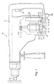
- FIG. 1 shows a longitudinal view of a Bohrhammers as an example of a hand tool
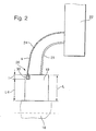
- Figure 2 is a schematic representation of a carbon brush Detection device.
- 10 denotes a rotary hammer, which as Example of a hand tool according to the invention is used.
- the hand machine tool has a housing 11 in which a electric drive motor 12 is housed.
- the Drive motor 12 has a motor shaft 13 on which a pinion 14 is arranged on the output side, via which the Drive motor 12, a transmission and not shown above it drives a tool 15 rotating and / or striking.
- the drive motor 12 is provided with a collector 18, with its outer circumference two opposite each other arranged brushes 19 in electrically conductive contact stand.
- a control device 22 is connected via an input line 17 depending on the respective switch position Switch 23 supplied with electrical drive energy.
- the Control device 22 makes contact via electrical lines 20, 21 the two opposite brushes 19 and controls the electric drive motor 12. Furthermore connect detection lines 24, 25 to the brushes arranged detection devices 26, 27 with the Control device 22.
- FIG. 2 shows a detection device known per se 26, which is formed on a brush 19, which cooperates with the collector 18.
- the Detection device 26 is that of collector 18 facing away from the rear of the brush 19 and over the Line 21 connected to the control device 22.
- the Detection device 26 consists of an isolated Wire piece 30, which is bent into a loop and in the Brush 19 integrated in the rear area, preferably is pressed or sintered therein.
- Detection device 26 i.e. the wire piece 30 over the To connect conductor 24 to the control device 22.
- Detection device 26 i.e. the wire piece 30 over the To connect conductor 24 to the control device 22.
- Detection device 26 At Reaching the minimum length l of the brush 19 is due to the damaged insulation of the piece of wire 30 from the Detection device 26 generates a detection signal s which via the conductor 24 to the control device 22 is forwarded.
- the control device 22 changes when the Detection signal s the electrical control of the Drive motor 12 in that the use of Handheld machine tool restricted or even impossible becomes. In this way, the operator is on electronic Paths signals that a change of brushes 19th is required.
- the change in control can consist, for example, that the drive motor 12 only runs slowly, or in Operation is booming.
- the detection signal s can also to generate a light signal or an acoustic Signals are processed further.
- a mechanical shut-off device for the brushes is included Handheld power tools equipped according to the invention are not more needed.
- the detection device 26 has a smaller one Distance l from the back of the brush 19 and therefore increases a significantly smaller proportion of the variable Total length L of the brushes 19 in claim.
- the available Abrasion length L-l of the brushes 19 is thus extended and the service life increases.
- the invention is not based on the above Embodiment limited. So it is enough one of the To provide brushes 19 with a detection device 26, since the brushes 19 experience fairly evenly be worn out and normally replaced at the same time Need to become.
- the hand machine tool can also do more than have two brushes 19.
Landscapes
- Engineering & Computer Science (AREA)
- Mechanical Engineering (AREA)
- Motor Or Generator Current Collectors (AREA)
Description
Claims (6)
- Handwerkzeugmaschine mit einem elektrischen Antriebsmotor (12), der einen Kommutator (18) aufweist, mit dem wenigstens zwei Bürsten (19) in elektrisch leitendem Kontakt stehen, wobei eine Detektionseinrichtung (26) vorgesehen ist, die bei Erreichen einer Mindestlänge (l) zumindest einer der Bürsten (19) ein Detektionssignal (s) erzeugt, wobei die Detektionseinrichtung (26) mit einer Steuereinrichtung (22) für den Antriebsmotor (12) verbunden ist, die bei Auftreten des Detektionssignals (s) eine Änderung der elektrischen Ansteuerung des Antriebsmotors (12) bewirkt, dadurch gekennzeichnet, dass der Antriebsmotor (12) bei Vorliegen des Detektionssignals (s) mit verringerter Leistung ansteuerbar ist.
- Handwerkzeugmaschine nach Anspruch 1, dadurch gekennzeichnet, dass das Detektionssignal(s) zusätzlich zur Erzeugung eines optischen und/oder akustischen Signals dient.
- Handwerkzeugmaschine nach Anspruch 1, dadurch gekennzeichnet, dass die Detektionseinrichtung (26) ein Drahtstück (30) aufweist, das an zumindest einer der Bürsten (19) in einem durch den Abrieb veränderbaren Abstand (L - 1) vom dem Kommutator (18) zugewandten Ende angeordnet ist.
- Handwerkzeugmaschine nach Anspruch 3, dadurch gekennzeichnet, dass das Drahtstück (30) durch eine Isolierschicht gegenüber der Bürste (19) isoliert ist.
- Handwerkzeugmaschine nach Anspruch 4, dadurch gekennzeichnet, dass das Drahtstück (30) über einen Detektionsleiter (24) mit der Steuereinrichtung (22) verbunden ist und bei abgeriebener Bürste (19) in elektrischen Kontakt mit der Bürste (19) bzw. dem Kommutator (18) gerät.
- Handwerkzeugmaschine nach einem der Ansprüche 3 bis 5, dadurch gekennzeichnet, dass das Drahtstück (30) in das dem Kommutator abgewandten Ende der Bürste (19) integriert ist.
Applications Claiming Priority (2)
| Application Number | Priority Date | Filing Date | Title |
|---|---|---|---|
| DE19703644A DE19703644A1 (de) | 1997-01-31 | 1997-01-31 | Handwerkzeugmaschine |
| DE19703644 | 1997-01-31 |
Publications (2)
| Publication Number | Publication Date |
|---|---|
| EP0856384A1 EP0856384A1 (de) | 1998-08-05 |
| EP0856384B1 true EP0856384B1 (de) | 2004-11-03 |
Family
ID=7818944
Family Applications (1)
| Application Number | Title | Priority Date | Filing Date |
|---|---|---|---|
| EP97121395A Expired - Lifetime EP0856384B1 (de) | 1997-01-31 | 1997-12-05 | Handwerkzeugmaschine mit einem Detektor, der bei Erreichen einer Mindestlänge der Kohlenbürsten ein Servicesignal erzeugt |
Country Status (2)
| Country | Link |
|---|---|
| EP (1) | EP0856384B1 (de) |
| DE (2) | DE19703644A1 (de) |
Families Citing this family (4)
| Publication number | Priority date | Publication date | Assignee | Title |
|---|---|---|---|---|
| DE102004003711A1 (de) * | 2004-01-24 | 2005-08-18 | Festool Gmbh | Elektrische Handwerkzeugmaschine, die einen insbesondere elektronisch kommutierten Elektromotor aufweist |
| DE102006009529A1 (de) * | 2006-02-28 | 2007-09-06 | Gefeg-Neckar Antriebssysteme Gmbh | Kommutatormotor mit integrierter Betriebselektronik |
| DE102010031415B4 (de) * | 2010-07-15 | 2016-07-07 | Schunk Kohlenstofftechnik Gmbh | Kohlebürste |
| CN112077799B (zh) * | 2019-06-14 | 2024-12-20 | 南京泉峰科技有限公司 | 一种电动工具 |
Family Cites Families (7)
| Publication number | Priority date | Publication date | Assignee | Title |
|---|---|---|---|---|
| DE7920943U1 (de) * | 1979-07-21 | 1979-11-22 | Rekofa Wenzel Gmbh & Co Kg, 5483 Bad Neuenahr-Ahrweiler | Kohlebürste mit Abschaltvorrichtung |
| US4536670A (en) * | 1981-12-14 | 1985-08-20 | Morganite Incorporated | Electrical brushes with wear sensors |
| DE8336769U1 (de) * | 1983-12-22 | 1984-04-26 | C. & E. Fein Gmbh & Co, 7000 Stuttgart | Elektrohandwerkzeug mit einer Umschaltvorrichtung für Rechts- und Linkslauf |
| US4739208A (en) * | 1986-11-13 | 1988-04-19 | General Electric Company | Brush assembly including brush wear detector |
| US4723084A (en) * | 1986-11-13 | 1988-02-02 | General Electric Company | Light conductor brush wear detector assembly |
| DE4137384C1 (en) * | 1991-11-14 | 1993-04-22 | Hilti Ag, Schaan, Li | Fault warning circuitry for electric power tool - has sensor built into motor to detect wear of carbon@ brushes |
| JPH09182384A (ja) * | 1995-12-27 | 1997-07-11 | Makita Corp | モータのブラシ摩耗報知装置 |
-
1997
- 1997-01-31 DE DE19703644A patent/DE19703644A1/de not_active Withdrawn
- 1997-12-05 DE DE59712061T patent/DE59712061D1/de not_active Expired - Lifetime
- 1997-12-05 EP EP97121395A patent/EP0856384B1/de not_active Expired - Lifetime
Also Published As
| Publication number | Publication date |
|---|---|
| EP0856384A1 (de) | 1998-08-05 |
| DE59712061D1 (de) | 2004-12-09 |
| DE19703644A1 (de) | 1998-08-06 |
Similar Documents
| Publication | Publication Date | Title |
|---|---|---|
| EP0918996B1 (de) | Motor mit drehzahlabgriff über einen hall-sensor | |
| EP1510300B1 (de) | Elektrowerkzeug | |
| EP1554086A1 (de) | Elektrowerkzeug | |
| DE2155457A1 (de) | Elektrowerkzeug mit kollektormotor | |
| DE102010031415B4 (de) | Kohlebürste | |
| EP0856384A1 (de) | Handwerkzeugmaschine mit einem Detektor, der bei Erreichen einer Mindestlänge der Kohlenbürsten ein Servicesignal erzeugt | |
| EP1096649A2 (de) | Bohrgerät | |
| EP1217742B1 (de) | Elektronischer Schalter, insbesondere Lichtschalter | |
| EP0960462B1 (de) | Bürstenhalteanordnung | |
| WO2000045474A1 (de) | Kohlebürste | |
| DE102018200195B4 (de) | Antrieb mit einem kommutatormotor | |
| DE29821736U1 (de) | Handwerkzeugmaschine | |
| EP1763123A1 (de) | Bürstensystem für einen Elektromotor, Bürstengehäuse mit einem derartigen Bürstensystem, Elektromotor mit einem Bürstengehäuse sowie Stellantrieb mit einem derartigen Elektromotor | |
| DE19750038A1 (de) | Vorrichtung zur Kontaktierung von Lamellen eines Kollektors eines Elektromotors | |
| EP1843452A1 (de) | Kohlehaltervorrichtung | |
| EP2067239A1 (de) | Elektrische antriebseinheit | |
| DE10001459B4 (de) | Elektrowerkzeuggerät mit Drehrichtungsumschalter | |
| DE102004040118A1 (de) | Kontakt mit einem Kontaktstift, einer Führung und einer Kontakteinrichtung zwischen diesen sowie Kontaktstift | |
| EP2553794A2 (de) | Handgeführtes elektrowerkzeug | |
| DE10065281A1 (de) | Elektromotor mit Bürstenhalter | |
| DE19853506B4 (de) | Akustischer Signalgeber | |
| EP1171942A1 (de) | Lagerschild für eine kommutatormaschine und verfahren zur herstellung eines solchen lagerschilds | |
| CH662219A5 (de) | Elektromotorisch betriebenes handgeraet. | |
| DE9405129U1 (de) | Kohle-Andruckfeder für einen Elektromotor | |
| DE202007003794U1 (de) | Anordnung zum Kontaktieren eines Funkentstörmittels mit einer elektrisch leitenden Gehäusekomponente einer Störquelle |
Legal Events
| Date | Code | Title | Description |
|---|---|---|---|
| PUAI | Public reference made under article 153(3) epc to a published international application that has entered the european phase |
Free format text: ORIGINAL CODE: 0009012 |
|
| AK | Designated contracting states |
Kind code of ref document: A1 Designated state(s): CH DE GB IT LI |
|
| AX | Request for extension of the european patent |
Free format text: AL;LT;LV;MK;RO;SI |
|
| 17P | Request for examination filed |
Effective date: 19990205 |
|
| AKX | Designation fees paid |
Free format text: CH DE GB IT LI |
|
| RBV | Designated contracting states (corrected) |
Designated state(s): CH DE GB IT LI |
|
| 17Q | First examination report despatched |
Effective date: 20030226 |
|
| GRAP | Despatch of communication of intention to grant a patent |
Free format text: ORIGINAL CODE: EPIDOSNIGR1 |
|
| GRAS | Grant fee paid |
Free format text: ORIGINAL CODE: EPIDOSNIGR3 |
|
| GRAA | (expected) grant |
Free format text: ORIGINAL CODE: 0009210 |
|
| AK | Designated contracting states |
Kind code of ref document: B1 Designated state(s): CH DE GB IT LI |
|
| PG25 | Lapsed in a contracting state [announced via postgrant information from national office to epo] |
Ref country code: IT Free format text: LAPSE BECAUSE OF FAILURE TO SUBMIT A TRANSLATION OF THE DESCRIPTION OR TO PAY THE FEE WITHIN THE PRESCRIBED TIME-LIMIT;WARNING: LAPSES OF ITALIAN PATENTS WITH EFFECTIVE DATE BEFORE 2007 MAY HAVE OCCURRED AT ANY TIME BEFORE 2007. THE CORRECT EFFECTIVE DATE MAY BE DIFFERENT FROM THE ONE RECORDED. Effective date: 20041103 |
|
| REG | Reference to a national code |
Ref country code: GB Ref legal event code: FG4D Free format text: NOT ENGLISH |
|
| REG | Reference to a national code |
Ref country code: CH Ref legal event code: NV Representative=s name: SCINTILLA AG, DIREKTION Ref country code: CH Ref legal event code: EP |
|
| REF | Corresponds to: |
Ref document number: 59712061 Country of ref document: DE Date of ref document: 20041209 Kind code of ref document: P |
|
| GBT | Gb: translation of ep patent filed (gb section 77(6)(a)/1977) |
Effective date: 20050228 |
|
| PLBE | No opposition filed within time limit |
Free format text: ORIGINAL CODE: 0009261 |
|
| STAA | Information on the status of an ep patent application or granted ep patent |
Free format text: STATUS: NO OPPOSITION FILED WITHIN TIME LIMIT |
|
| 26N | No opposition filed |
Effective date: 20050804 |
|
| PGFP | Annual fee paid to national office [announced via postgrant information from national office to epo] |
Ref country code: CH Payment date: 20081222 Year of fee payment: 12 |
|
| PGFP | Annual fee paid to national office [announced via postgrant information from national office to epo] |
Ref country code: DE Payment date: 20100218 Year of fee payment: 13 |
|
| REG | Reference to a national code |
Ref country code: CH Ref legal event code: PL |
|
| PG25 | Lapsed in a contracting state [announced via postgrant information from national office to epo] |
Ref country code: LI Free format text: LAPSE BECAUSE OF NON-PAYMENT OF DUE FEES Effective date: 20091231 Ref country code: CH Free format text: LAPSE BECAUSE OF NON-PAYMENT OF DUE FEES Effective date: 20091231 |
|
| PGFP | Annual fee paid to national office [announced via postgrant information from national office to epo] |
Ref country code: GB Payment date: 20101221 Year of fee payment: 14 |
|
| REG | Reference to a national code |
Ref country code: DE Ref legal event code: R119 Ref document number: 59712061 Country of ref document: DE Effective date: 20110701 |
|
| PG25 | Lapsed in a contracting state [announced via postgrant information from national office to epo] |
Ref country code: DE Free format text: LAPSE BECAUSE OF NON-PAYMENT OF DUE FEES Effective date: 20110701 |
|
| GBPC | Gb: european patent ceased through non-payment of renewal fee |
Effective date: 20111205 |
|
| PG25 | Lapsed in a contracting state [announced via postgrant information from national office to epo] |
Ref country code: GB Free format text: LAPSE BECAUSE OF NON-PAYMENT OF DUE FEES Effective date: 20111205 |