EP0856088B1 - Articles magnetiques deformables appliques sous des couches de roulement de chaussees - Google Patents
Articles magnetiques deformables appliques sous des couches de roulement de chaussees Download PDFInfo
- Publication number
- EP0856088B1 EP0856088B1 EP96937681A EP96937681A EP0856088B1 EP 0856088 B1 EP0856088 B1 EP 0856088B1 EP 96937681 A EP96937681 A EP 96937681A EP 96937681 A EP96937681 A EP 96937681A EP 0856088 B1 EP0856088 B1 EP 0856088B1
- Authority
- EP
- European Patent Office
- Prior art keywords
- magnetic
- traffic
- article
- bearing structure
- layer
- Prior art date
- Legal status (The legal status is an assumption and is not a legal conclusion. Google has not performed a legal analysis and makes no representation as to the accuracy of the status listed.)
- Expired - Lifetime
Links
- 239000011230 binding agent Substances 0.000 claims abstract description 26
- 239000006249 magnetic particle Substances 0.000 claims abstract description 26
- 239000000463 material Substances 0.000 claims description 76
- 238000000034 method Methods 0.000 claims description 22
- 239000010426 asphalt Substances 0.000 claims description 19
- 239000004820 Pressure-sensitive adhesive Substances 0.000 claims description 6
- 239000004567 concrete Substances 0.000 claims description 6
- 239000004568 cement Substances 0.000 claims description 5
- 230000001747 exhibiting effect Effects 0.000 claims description 4
- 239000011398 Portland cement Substances 0.000 claims description 2
- 239000000758 substrate Substances 0.000 claims 3
- 239000010410 layer Substances 0.000 description 91
- 239000000523 sample Substances 0.000 description 45
- 239000002245 particle Substances 0.000 description 38
- 239000003981 vehicle Substances 0.000 description 29
- 238000012360 testing method Methods 0.000 description 15
- 229920001971 elastomer Polymers 0.000 description 12
- 239000012790 adhesive layer Substances 0.000 description 10
- 239000000853 adhesive Substances 0.000 description 9
- 230000001070 adhesive effect Effects 0.000 description 9
- 230000005415 magnetization Effects 0.000 description 8
- 239000004005 microsphere Substances 0.000 description 8
- 229920000642 polymer Polymers 0.000 description 8
- 238000011084 recovery Methods 0.000 description 8
- 239000000126 substance Substances 0.000 description 8
- 239000000806 elastomer Substances 0.000 description 7
- 239000000835 fiber Substances 0.000 description 7
- 230000035515 penetration Effects 0.000 description 7
- 229920002635 polyurethane Polymers 0.000 description 7
- 239000004814 polyurethane Substances 0.000 description 7
- XEEYBQQBJWHFJM-UHFFFAOYSA-N Iron Chemical compound [Fe] XEEYBQQBJWHFJM-UHFFFAOYSA-N 0.000 description 6
- 229910045601 alloy Inorganic materials 0.000 description 6
- 239000000956 alloy Substances 0.000 description 6
- 238000007664 blowing Methods 0.000 description 6
- 239000007788 liquid Substances 0.000 description 6
- 239000000696 magnetic material Substances 0.000 description 6
- 239000000203 mixture Substances 0.000 description 6
- 229920001169 thermoplastic Polymers 0.000 description 6
- 229920002554 vinyl polymer Polymers 0.000 description 6
- 230000008901 benefit Effects 0.000 description 5
- 239000006185 dispersion Substances 0.000 description 5
- 239000003973 paint Substances 0.000 description 5
- 239000000049 pigment Substances 0.000 description 5
- 239000002243 precursor Substances 0.000 description 5
- 239000005060 rubber Substances 0.000 description 5
- 230000000930 thermomechanical effect Effects 0.000 description 5
- 125000000391 vinyl group Chemical group [H]C([*])=C([H])[H] 0.000 description 5
- 230000000007 visual effect Effects 0.000 description 5
- 229910000859 α-Fe Inorganic materials 0.000 description 5
- 238000003490 calendering Methods 0.000 description 4
- 238000005336 cracking Methods 0.000 description 4
- -1 gravel Substances 0.000 description 4
- 239000004615 ingredient Substances 0.000 description 4
- 230000008569 process Effects 0.000 description 4
- 230000003014 reinforcing effect Effects 0.000 description 4
- 239000011347 resin Substances 0.000 description 4
- 229920005989 resin Polymers 0.000 description 4
- 239000004606 Fillers/Extenders Substances 0.000 description 3
- HPYIMVBXZPJVBV-UHFFFAOYSA-N barium(2+);iron(3+);oxygen(2-) Chemical compound [O-2].[O-2].[O-2].[O-2].[O-2].[O-2].[O-2].[O-2].[O-2].[O-2].[O-2].[O-2].[O-2].[O-2].[O-2].[O-2].[O-2].[O-2].[O-2].[Fe+3].[Fe+3].[Fe+3].[Fe+3].[Fe+3].[Fe+3].[Fe+3].[Fe+3].[Fe+3].[Fe+3].[Fe+3].[Fe+3].[Ba+2] HPYIMVBXZPJVBV-UHFFFAOYSA-N 0.000 description 3
- 239000004841 bisphenol A epoxy resin Substances 0.000 description 3
- 150000001875 compounds Chemical class 0.000 description 3
- 238000010276 construction Methods 0.000 description 3
- 230000007797 corrosion Effects 0.000 description 3
- 238000005260 corrosion Methods 0.000 description 3
- GYZLOYUZLJXAJU-UHFFFAOYSA-N diglycidyl ether Chemical compound C1OC1COCC1CO1 GYZLOYUZLJXAJU-UHFFFAOYSA-N 0.000 description 3
- 229910052742 iron Inorganic materials 0.000 description 3
- UQSXHKLRYXJYBZ-UHFFFAOYSA-N iron oxide Inorganic materials [Fe]=O UQSXHKLRYXJYBZ-UHFFFAOYSA-N 0.000 description 3
- SZVJSHCCFOBDDC-UHFFFAOYSA-N iron(II,III) oxide Inorganic materials O=[Fe]O[Fe]O[Fe]=O SZVJSHCCFOBDDC-UHFFFAOYSA-N 0.000 description 3
- 239000003550 marker Substances 0.000 description 3
- 229910052712 strontium Inorganic materials 0.000 description 3
- CIOAGBVUUVVLOB-UHFFFAOYSA-N strontium atom Chemical compound [Sr] CIOAGBVUUVVLOB-UHFFFAOYSA-N 0.000 description 3
- 239000004416 thermosoftening plastic Substances 0.000 description 3
- 229920000089 Cyclic olefin copolymer Polymers 0.000 description 2
- 239000004593 Epoxy Substances 0.000 description 2
- NTIZESTWPVYFNL-UHFFFAOYSA-N Methyl isobutyl ketone Chemical compound CC(C)CC(C)=O NTIZESTWPVYFNL-UHFFFAOYSA-N 0.000 description 2
- UIHCLUNTQKBZGK-UHFFFAOYSA-N Methyl isobutyl ketone Natural products CCC(C)C(C)=O UIHCLUNTQKBZGK-UHFFFAOYSA-N 0.000 description 2
- 229920000459 Nitrile rubber Polymers 0.000 description 2
- 239000004698 Polyethylene Substances 0.000 description 2
- 235000021355 Stearic acid Nutrition 0.000 description 2
- 229910052788 barium Inorganic materials 0.000 description 2
- DSAJWYNOEDNPEQ-UHFFFAOYSA-N barium atom Chemical compound [Ba] DSAJWYNOEDNPEQ-UHFFFAOYSA-N 0.000 description 2
- 230000009286 beneficial effect Effects 0.000 description 2
- KYAZRUPZRJALEP-UHFFFAOYSA-N bismuth manganese Chemical compound [Mn].[Bi] KYAZRUPZRJALEP-UHFFFAOYSA-N 0.000 description 2
- 239000011449 brick Substances 0.000 description 2
- 239000002131 composite material Substances 0.000 description 2
- 238000013329 compounding Methods 0.000 description 2
- 230000007423 decrease Effects 0.000 description 2
- 238000001514 detection method Methods 0.000 description 2
- 239000000428 dust Substances 0.000 description 2
- 238000001125 extrusion Methods 0.000 description 2
- 230000001771 impaired effect Effects 0.000 description 2
- 238000009434 installation Methods 0.000 description 2
- 239000000543 intermediate Substances 0.000 description 2
- 239000011159 matrix material Substances 0.000 description 2
- 238000005259 measurement Methods 0.000 description 2
- 229910052751 metal Inorganic materials 0.000 description 2
- 239000002184 metal Substances 0.000 description 2
- 238000012986 modification Methods 0.000 description 2
- 230000004048 modification Effects 0.000 description 2
- QIQXTHQIDYTFRH-UHFFFAOYSA-N octadecanoic acid Chemical compound CCCCCCCCCCCCCCCCCC(O)=O QIQXTHQIDYTFRH-UHFFFAOYSA-N 0.000 description 2
- OQCDKBAXFALNLD-UHFFFAOYSA-N octadecanoic acid Natural products CCCCCCCC(C)CCCCCCCCC(O)=O OQCDKBAXFALNLD-UHFFFAOYSA-N 0.000 description 2
- 230000003287 optical effect Effects 0.000 description 2
- 239000012188 paraffin wax Substances 0.000 description 2
- 229920000058 polyacrylate Polymers 0.000 description 2
- 229920000728 polyester Polymers 0.000 description 2
- 229920000098 polyolefin Polymers 0.000 description 2
- 230000002028 premature Effects 0.000 description 2
- 238000012545 processing Methods 0.000 description 2
- 230000002035 prolonged effect Effects 0.000 description 2
- 229910052761 rare earth metal Inorganic materials 0.000 description 2
- 150000002910 rare earth metals Chemical class 0.000 description 2
- 239000007787 solid Substances 0.000 description 2
- 239000008117 stearic acid Substances 0.000 description 2
- IFNXAMCERSVZCV-UHFFFAOYSA-L zinc;2-ethylhexanoate Chemical compound [Zn+2].CCCCC(CC)C([O-])=O.CCCCC(CC)C([O-])=O IFNXAMCERSVZCV-UHFFFAOYSA-L 0.000 description 2
- XTFIVUDBNACUBN-UHFFFAOYSA-N 1,3,5-trinitro-1,3,5-triazinane Chemical compound [O-][N+](=O)N1CN([N+]([O-])=O)CN([N+]([O-])=O)C1 XTFIVUDBNACUBN-UHFFFAOYSA-N 0.000 description 1
- HXIQYSLFEXIOAV-UHFFFAOYSA-N 2-tert-butyl-4-(5-tert-butyl-4-hydroxy-2-methylphenyl)sulfanyl-5-methylphenol Chemical class CC1=CC(O)=C(C(C)(C)C)C=C1SC1=CC(C(C)(C)C)=C(O)C=C1C HXIQYSLFEXIOAV-UHFFFAOYSA-N 0.000 description 1
- NLHHRLWOUZZQLW-UHFFFAOYSA-N Acrylonitrile Chemical compound C=CC#N NLHHRLWOUZZQLW-UHFFFAOYSA-N 0.000 description 1
- 102100029647 Apoptosis-associated speck-like protein containing a CARD Human genes 0.000 description 1
- 229910001313 Cobalt-iron alloy Inorganic materials 0.000 description 1
- 239000004821 Contact adhesive Substances 0.000 description 1
- LFQSCWFLJHTTHZ-UHFFFAOYSA-N Ethanol Chemical compound CCO LFQSCWFLJHTTHZ-UHFFFAOYSA-N 0.000 description 1
- CWYNVVGOOAEACU-UHFFFAOYSA-N Fe2+ Chemical compound [Fe+2] CWYNVVGOOAEACU-UHFFFAOYSA-N 0.000 description 1
- 230000005355 Hall effect Effects 0.000 description 1
- 244000043261 Hevea brasiliensis Species 0.000 description 1
- 101000728679 Homo sapiens Apoptosis-associated speck-like protein containing a CARD Proteins 0.000 description 1
- 101000707471 Homo sapiens Serine incorporator 3 Proteins 0.000 description 1
- 239000013032 Hydrocarbon resin Substances 0.000 description 1
- 241001465754 Metazoa Species 0.000 description 1
- WYNCHZVNFNFDNH-UHFFFAOYSA-N Oxazolidine Chemical group C1COCN1 WYNCHZVNFNFDNH-UHFFFAOYSA-N 0.000 description 1
- 229920013649 Paracril Polymers 0.000 description 1
- 229920012485 Plasticized Polyvinyl chloride Polymers 0.000 description 1
- 239000004793 Polystyrene Substances 0.000 description 1
- 239000004614 Process Aid Substances 0.000 description 1
- 229910001260 Pt alloy Inorganic materials 0.000 description 1
- 229910000831 Steel Inorganic materials 0.000 description 1
- 239000002174 Styrene-butadiene Substances 0.000 description 1
- 229920000690 Tyvek Polymers 0.000 description 1
- QJVKUMXDEUEQLH-UHFFFAOYSA-N [B].[Fe].[Nd] Chemical compound [B].[Fe].[Nd] QJVKUMXDEUEQLH-UHFFFAOYSA-N 0.000 description 1
- QVYYOKWPCQYKEY-UHFFFAOYSA-N [Fe].[Co] Chemical compound [Fe].[Co] QVYYOKWPCQYKEY-UHFFFAOYSA-N 0.000 description 1
- ZMXPKUWNBXIACW-UHFFFAOYSA-N [Fe].[Co].[Mo] Chemical compound [Fe].[Co].[Mo] ZMXPKUWNBXIACW-UHFFFAOYSA-N 0.000 description 1
- WBWJXRJARNTNBL-UHFFFAOYSA-N [Fe].[Cr].[Co] Chemical compound [Fe].[Cr].[Co] WBWJXRJARNTNBL-UHFFFAOYSA-N 0.000 description 1
- ABEXMJLMICYACI-UHFFFAOYSA-N [V].[Co].[Fe] Chemical compound [V].[Co].[Fe] ABEXMJLMICYACI-UHFFFAOYSA-N 0.000 description 1
- 238000005299 abrasion Methods 0.000 description 1
- 239000002253 acid Substances 0.000 description 1
- 230000002378 acidificating effect Effects 0.000 description 1
- 230000002411 adverse Effects 0.000 description 1
- 229910000828 alnico Inorganic materials 0.000 description 1
- 230000004075 alteration Effects 0.000 description 1
- 229910052782 aluminium Inorganic materials 0.000 description 1
- XAGFODPZIPBFFR-UHFFFAOYSA-N aluminium Chemical compound [Al] XAGFODPZIPBFFR-UHFFFAOYSA-N 0.000 description 1
- 239000012080 ambient air Substances 0.000 description 1
- 238000004458 analytical method Methods 0.000 description 1
- 239000003963 antioxidant agent Substances 0.000 description 1
- 230000003078 antioxidant effect Effects 0.000 description 1
- 238000013459 approach Methods 0.000 description 1
- 239000011384 asphalt concrete Substances 0.000 description 1
- 239000012298 atmosphere Substances 0.000 description 1
- 239000011324 bead Substances 0.000 description 1
- NTXGQCSETZTARF-UHFFFAOYSA-N buta-1,3-diene;prop-2-enenitrile Chemical compound C=CC=C.C=CC#N NTXGQCSETZTARF-UHFFFAOYSA-N 0.000 description 1
- MTAZNLWOLGHBHU-UHFFFAOYSA-N butadiene-styrene rubber Chemical compound C=CC=C.C=CC1=CC=CC=C1 MTAZNLWOLGHBHU-UHFFFAOYSA-N 0.000 description 1
- 239000003054 catalyst Substances 0.000 description 1
- 229920002678 cellulose Polymers 0.000 description 1
- 239000001913 cellulose Substances 0.000 description 1
- 239000000919 ceramic Substances 0.000 description 1
- 230000008859 change Effects 0.000 description 1
- 239000002738 chelating agent Substances 0.000 description 1
- 239000003795 chemical substances by application Substances 0.000 description 1
- 229940090961 chromium dioxide Drugs 0.000 description 1
- IAQWMWUKBQPOIY-UHFFFAOYSA-N chromium(4+);oxygen(2-) Chemical compound [O-2].[O-2].[Cr+4] IAQWMWUKBQPOIY-UHFFFAOYSA-N 0.000 description 1
- AYTAKQFHWFYBMA-UHFFFAOYSA-N chromium(IV) oxide Inorganic materials O=[Cr]=O AYTAKQFHWFYBMA-UHFFFAOYSA-N 0.000 description 1
- 239000004927 clay Substances 0.000 description 1
- 239000011248 coating agent Substances 0.000 description 1
- 238000000576 coating method Methods 0.000 description 1
- AVMBSRQXOWNFTR-UHFFFAOYSA-N cobalt platinum Chemical compound [Pt][Co][Pt] AVMBSRQXOWNFTR-UHFFFAOYSA-N 0.000 description 1
- KPLQYGBQNPPQGA-UHFFFAOYSA-N cobalt samarium Chemical compound [Co].[Sm] KPLQYGBQNPPQGA-UHFFFAOYSA-N 0.000 description 1
- GOECOOJIPSGIIV-UHFFFAOYSA-N copper iron nickel Chemical compound [Fe].[Ni].[Cu] GOECOOJIPSGIIV-UHFFFAOYSA-N 0.000 description 1
- 239000013078 crystal Substances 0.000 description 1
- 238000005520 cutting process Methods 0.000 description 1
- 238000013016 damping Methods 0.000 description 1
- 230000007547 defect Effects 0.000 description 1
- 238000010586 diagram Methods 0.000 description 1
- 150000002009 diols Chemical class 0.000 description 1
- 239000013013 elastic material Substances 0.000 description 1
- 238000002474 experimental method Methods 0.000 description 1
- 230000009969 flowable effect Effects 0.000 description 1
- 230000004907 flux Effects 0.000 description 1
- 231100001261 hazardous Toxicity 0.000 description 1
- 229910052734 helium Inorganic materials 0.000 description 1
- 239000001307 helium Substances 0.000 description 1
- SWQJXJOGLNCZEY-UHFFFAOYSA-N helium atom Chemical compound [He] SWQJXJOGLNCZEY-UHFFFAOYSA-N 0.000 description 1
- RRAMGCGOFNQTLD-UHFFFAOYSA-N hexamethylene diisocyanate Chemical class O=C=NCCCCCCN=C=O RRAMGCGOFNQTLD-UHFFFAOYSA-N 0.000 description 1
- 239000012943 hotmelt Substances 0.000 description 1
- 229920006270 hydrocarbon resin Polymers 0.000 description 1
- UCNNJGDEJXIUCC-UHFFFAOYSA-L hydroxy(oxo)iron;iron Chemical compound [Fe].O[Fe]=O.O[Fe]=O UCNNJGDEJXIUCC-UHFFFAOYSA-L 0.000 description 1
- 238000010348 incorporation Methods 0.000 description 1
- 229910052500 inorganic mineral Inorganic materials 0.000 description 1
- 230000001788 irregular Effects 0.000 description 1
- 238000004898 kneading Methods 0.000 description 1
- 239000012762 magnetic filler Substances 0.000 description 1
- 238000012423 maintenance Methods 0.000 description 1
- 238000004519 manufacturing process Methods 0.000 description 1
- 229910001092 metal group alloy Inorganic materials 0.000 description 1
- QMQXDJATSGGYDR-UHFFFAOYSA-N methylidyneiron Chemical compound [C].[Fe] QMQXDJATSGGYDR-UHFFFAOYSA-N 0.000 description 1
- 239000011707 mineral Substances 0.000 description 1
- 238000005065 mining Methods 0.000 description 1
- 239000000178 monomer Substances 0.000 description 1
- 229920003052 natural elastomer Polymers 0.000 description 1
- 229920001194 natural rubber Polymers 0.000 description 1
- 229910001172 neodymium magnet Inorganic materials 0.000 description 1
- 150000002825 nitriles Chemical class 0.000 description 1
- 239000000820 nonprescription drug Substances 0.000 description 1
- 230000003647 oxidation Effects 0.000 description 1
- 238000007254 oxidation reaction Methods 0.000 description 1
- NDLPOXTZKUMGOV-UHFFFAOYSA-N oxo(oxoferriooxy)iron hydrate Chemical compound O.O=[Fe]O[Fe]=O NDLPOXTZKUMGOV-UHFFFAOYSA-N 0.000 description 1
- 239000011236 particulate material Substances 0.000 description 1
- 239000013618 particulate matter Substances 0.000 description 1
- 230000000737 periodic effect Effects 0.000 description 1
- 229920002587 poly(1,3-butadiene) polymer Polymers 0.000 description 1
- 229920001084 poly(chloroprene) Polymers 0.000 description 1
- 229920002285 poly(styrene-co-acrylonitrile) Polymers 0.000 description 1
- 229920001610 polycaprolactone Polymers 0.000 description 1
- 239000004632 polycaprolactone Substances 0.000 description 1
- 229920000570 polyether Polymers 0.000 description 1
- 239000005056 polyisocyanate Substances 0.000 description 1
- 229920001228 polyisocyanate Polymers 0.000 description 1
- 229920002223 polystyrene Polymers 0.000 description 1
- 238000002360 preparation method Methods 0.000 description 1
- 238000004080 punching Methods 0.000 description 1
- 239000001054 red pigment Substances 0.000 description 1
- 230000002787 reinforcement Effects 0.000 description 1
- 239000012858 resilient material Substances 0.000 description 1
- 230000004044 response Effects 0.000 description 1
- 230000000284 resting effect Effects 0.000 description 1
- 239000011435 rock Substances 0.000 description 1
- 238000010057 rubber processing Methods 0.000 description 1
- 229910000938 samarium–cobalt magnet Inorganic materials 0.000 description 1
- 238000007789 sealing Methods 0.000 description 1
- 229920002379 silicone rubber Polymers 0.000 description 1
- 239000004945 silicone rubber Substances 0.000 description 1
- 239000000779 smoke Substances 0.000 description 1
- 239000002904 solvent Substances 0.000 description 1
- 239000003381 stabilizer Substances 0.000 description 1
- 239000010959 steel Substances 0.000 description 1
- 230000000638 stimulation Effects 0.000 description 1
- 239000011115 styrene butadiene Substances 0.000 description 1
- 229920003048 styrene butadiene rubber Polymers 0.000 description 1
- 239000002344 surface layer Substances 0.000 description 1
- 238000004441 surface measurement Methods 0.000 description 1
- 229920005992 thermoplastic resin Polymers 0.000 description 1
- 229920001187 thermosetting polymer Polymers 0.000 description 1
- 230000007704 transition Effects 0.000 description 1
- 150000004072 triols Chemical class 0.000 description 1
- 229920006163 vinyl copolymer Polymers 0.000 description 1
- 239000012463 white pigment Substances 0.000 description 1
- 239000002023 wood Substances 0.000 description 1
- CHJMFFKHPHCQIJ-UHFFFAOYSA-L zinc;octanoate Chemical compound [Zn+2].CCCCCCCC([O-])=O.CCCCCCCC([O-])=O CHJMFFKHPHCQIJ-UHFFFAOYSA-L 0.000 description 1
Images
Classifications
-
- B—PERFORMING OPERATIONS; TRANSPORTING
- B32—LAYERED PRODUCTS
- B32B—LAYERED PRODUCTS, i.e. PRODUCTS BUILT-UP OF STRATA OF FLAT OR NON-FLAT, e.g. CELLULAR OR HONEYCOMB, FORM
- B32B5/00—Layered products characterised by the non- homogeneity or physical structure, i.e. comprising a fibrous, filamentary, particulate or foam layer; Layered products characterised by having a layer differing constitutionally or physically in different parts
- B32B5/16—Layered products characterised by the non- homogeneity or physical structure, i.e. comprising a fibrous, filamentary, particulate or foam layer; Layered products characterised by having a layer differing constitutionally or physically in different parts characterised by features of a layer formed of particles, e.g. chips, powder or granules
-
- B—PERFORMING OPERATIONS; TRANSPORTING
- B32—LAYERED PRODUCTS
- B32B—LAYERED PRODUCTS, i.e. PRODUCTS BUILT-UP OF STRATA OF FLAT OR NON-FLAT, e.g. CELLULAR OR HONEYCOMB, FORM
- B32B13/00—Layered products comprising a a layer of water-setting substance, e.g. concrete, plaster, asbestos cement, or like builders' material
- B32B13/04—Layered products comprising a a layer of water-setting substance, e.g. concrete, plaster, asbestos cement, or like builders' material comprising such water setting substance as the main or only constituent of a layer, which is next to another layer of the same or of a different material
- B32B13/047—Layered products comprising a a layer of water-setting substance, e.g. concrete, plaster, asbestos cement, or like builders' material comprising such water setting substance as the main or only constituent of a layer, which is next to another layer of the same or of a different material made of particles
-
- B—PERFORMING OPERATIONS; TRANSPORTING
- B32—LAYERED PRODUCTS
- B32B—LAYERED PRODUCTS, i.e. PRODUCTS BUILT-UP OF STRATA OF FLAT OR NON-FLAT, e.g. CELLULAR OR HONEYCOMB, FORM
- B32B7/00—Layered products characterised by the relation between layers; Layered products characterised by the relative orientation of features between layers, or by the relative values of a measurable parameter between layers, i.e. products comprising layers having different physical, chemical or physicochemical properties; Layered products characterised by the interconnection of layers
- B32B7/04—Interconnection of layers
- B32B7/12—Interconnection of layers using interposed adhesives or interposed materials with bonding properties
-
- E—FIXED CONSTRUCTIONS
- E01—CONSTRUCTION OF ROADS, RAILWAYS, OR BRIDGES
- E01F—ADDITIONAL WORK, SUCH AS EQUIPPING ROADS OR THE CONSTRUCTION OF PLATFORMS, HELICOPTER LANDING STAGES, SIGNS, SNOW FENCES, OR THE LIKE
- E01F11/00—Road engineering aspects of Embedding pads or other sensitive devices in paving or other road surfaces, e.g. traffic detectors, vehicle-operated pressure-sensitive actuators, devices for monitoring atmospheric or road conditions
-
- E—FIXED CONSTRUCTIONS
- E01—CONSTRUCTION OF ROADS, RAILWAYS, OR BRIDGES
- E01F—ADDITIONAL WORK, SUCH AS EQUIPPING ROADS OR THE CONSTRUCTION OF PLATFORMS, HELICOPTER LANDING STAGES, SIGNS, SNOW FENCES, OR THE LIKE
- E01F9/00—Arrangement of road signs or traffic signals; Arrangements for enforcing caution
- E01F9/30—Arrangements interacting with transmitters or receivers otherwise than by visible means, e.g. using radar reflectors or radio transmitters
-
- E—FIXED CONSTRUCTIONS
- E01—CONSTRUCTION OF ROADS, RAILWAYS, OR BRIDGES
- E01F—ADDITIONAL WORK, SUCH AS EQUIPPING ROADS OR THE CONSTRUCTION OF PLATFORMS, HELICOPTER LANDING STAGES, SIGNS, SNOW FENCES, OR THE LIKE
- E01F9/00—Arrangement of road signs or traffic signals; Arrangements for enforcing caution
- E01F9/50—Road surface markings; Kerbs or road edgings, specially adapted for alerting road users
- E01F9/506—Road surface markings; Kerbs or road edgings, specially adapted for alerting road users characterised by the road surface marking material, e.g. comprising additives for improving friction or reflectivity; Methods of forming, installing or applying markings in, on or to road surfaces
- E01F9/512—Preformed road surface markings, e.g. of sheet material; Methods of applying preformed markings
-
- G—PHYSICS
- G05—CONTROLLING; REGULATING
- G05D—SYSTEMS FOR CONTROLLING OR REGULATING NON-ELECTRIC VARIABLES
- G05D1/00—Control of position, course or altitude of land, water, air, or space vehicles, e.g. automatic pilot
- G05D1/02—Control of position or course in two dimensions
- G05D1/021—Control of position or course in two dimensions specially adapted to land vehicles
- G05D1/0259—Control of position or course in two dimensions specially adapted to land vehicles using magnetic or electromagnetic means
- G05D1/0263—Control of position or course in two dimensions specially adapted to land vehicles using magnetic or electromagnetic means using magnetic strips
-
- Y—GENERAL TAGGING OF NEW TECHNOLOGICAL DEVELOPMENTS; GENERAL TAGGING OF CROSS-SECTIONAL TECHNOLOGIES SPANNING OVER SEVERAL SECTIONS OF THE IPC; TECHNICAL SUBJECTS COVERED BY FORMER USPC CROSS-REFERENCE ART COLLECTIONS [XRACs] AND DIGESTS
- Y10—TECHNICAL SUBJECTS COVERED BY FORMER USPC
- Y10S—TECHNICAL SUBJECTS COVERED BY FORMER USPC CROSS-REFERENCE ART COLLECTIONS [XRACs] AND DIGESTS
- Y10S428/00—Stock material or miscellaneous articles
- Y10S428/90—Magnetic feature
-
- Y—GENERAL TAGGING OF NEW TECHNOLOGICAL DEVELOPMENTS; GENERAL TAGGING OF CROSS-SECTIONAL TECHNOLOGIES SPANNING OVER SEVERAL SECTIONS OF THE IPC; TECHNICAL SUBJECTS COVERED BY FORMER USPC CROSS-REFERENCE ART COLLECTIONS [XRACs] AND DIGESTS
- Y10—TECHNICAL SUBJECTS COVERED BY FORMER USPC
- Y10T—TECHNICAL SUBJECTS COVERED BY FORMER US CLASSIFICATION
- Y10T428/00—Stock material or miscellaneous articles
- Y10T428/24—Structurally defined web or sheet [e.g., overall dimension, etc.]
- Y10T428/24273—Structurally defined web or sheet [e.g., overall dimension, etc.] including aperture
-
- Y—GENERAL TAGGING OF NEW TECHNOLOGICAL DEVELOPMENTS; GENERAL TAGGING OF CROSS-SECTIONAL TECHNOLOGIES SPANNING OVER SEVERAL SECTIONS OF THE IPC; TECHNICAL SUBJECTS COVERED BY FORMER USPC CROSS-REFERENCE ART COLLECTIONS [XRACs] AND DIGESTS
- Y10—TECHNICAL SUBJECTS COVERED BY FORMER USPC
- Y10T—TECHNICAL SUBJECTS COVERED BY FORMER US CLASSIFICATION
- Y10T428/00—Stock material or miscellaneous articles
- Y10T428/24—Structurally defined web or sheet [e.g., overall dimension, etc.]
- Y10T428/24355—Continuous and nonuniform or irregular surface on layer or component [e.g., roofing, etc.]
- Y10T428/24372—Particulate matter
- Y10T428/24421—Silicon containing
-
- Y—GENERAL TAGGING OF NEW TECHNOLOGICAL DEVELOPMENTS; GENERAL TAGGING OF CROSS-SECTIONAL TECHNOLOGIES SPANNING OVER SEVERAL SECTIONS OF THE IPC; TECHNICAL SUBJECTS COVERED BY FORMER USPC CROSS-REFERENCE ART COLLECTIONS [XRACs] AND DIGESTS
- Y10—TECHNICAL SUBJECTS COVERED BY FORMER USPC
- Y10T—TECHNICAL SUBJECTS COVERED BY FORMER US CLASSIFICATION
- Y10T428/00—Stock material or miscellaneous articles
- Y10T428/24—Structurally defined web or sheet [e.g., overall dimension, etc.]
- Y10T428/24479—Structurally defined web or sheet [e.g., overall dimension, etc.] including variation in thickness
-
- Y—GENERAL TAGGING OF NEW TECHNOLOGICAL DEVELOPMENTS; GENERAL TAGGING OF CROSS-SECTIONAL TECHNOLOGIES SPANNING OVER SEVERAL SECTIONS OF THE IPC; TECHNICAL SUBJECTS COVERED BY FORMER USPC CROSS-REFERENCE ART COLLECTIONS [XRACs] AND DIGESTS
- Y10—TECHNICAL SUBJECTS COVERED BY FORMER USPC
- Y10T—TECHNICAL SUBJECTS COVERED BY FORMER US CLASSIFICATION
- Y10T428/00—Stock material or miscellaneous articles
- Y10T428/25—Web or sheet containing structurally defined element or component and including a second component containing structurally defined particles
- Y10T428/252—Glass or ceramic [i.e., fired or glazed clay, cement, etc.] [porcelain, quartz, etc.]
-
- Y—GENERAL TAGGING OF NEW TECHNOLOGICAL DEVELOPMENTS; GENERAL TAGGING OF CROSS-SECTIONAL TECHNOLOGIES SPANNING OVER SEVERAL SECTIONS OF THE IPC; TECHNICAL SUBJECTS COVERED BY FORMER USPC CROSS-REFERENCE ART COLLECTIONS [XRACs] AND DIGESTS
- Y10—TECHNICAL SUBJECTS COVERED BY FORMER USPC
- Y10T—TECHNICAL SUBJECTS COVERED BY FORMER US CLASSIFICATION
- Y10T428/00—Stock material or miscellaneous articles
- Y10T428/28—Web or sheet containing structurally defined element or component and having an adhesive outermost layer
-
- Y—GENERAL TAGGING OF NEW TECHNOLOGICAL DEVELOPMENTS; GENERAL TAGGING OF CROSS-SECTIONAL TECHNOLOGIES SPANNING OVER SEVERAL SECTIONS OF THE IPC; TECHNICAL SUBJECTS COVERED BY FORMER USPC CROSS-REFERENCE ART COLLECTIONS [XRACs] AND DIGESTS
- Y10—TECHNICAL SUBJECTS COVERED BY FORMER USPC
- Y10T—TECHNICAL SUBJECTS COVERED BY FORMER US CLASSIFICATION
- Y10T428/00—Stock material or miscellaneous articles
- Y10T428/32—Composite [nonstructural laminate] of inorganic material having metal-compound-containing layer and having defined magnetic layer
Definitions
- the present invention relates to the field of magnetic articles, in particular, to articles which may be underlaid beneath a traffic-bearing surface such as a roadway, warehouse floor, and the like, to guide a vehicle or other mobile object thereon.
- Inclement weather and even blinding sunlight or oncoming traffic light present special problems both for existing travel systems and for guidance systems that offer lateral vehicle control.
- An unfortunate number of tragic accidents have occurred due to people driving under the influence of alcohol and over-the-counter medicines.
- Snowy conditions, fog, heavy rain, blowing dust and smoke are examples of challenges to vehicle drivers.
- Snowy weather presents particularly challenging driving conditions to snowplow drivers trying to clear lanes in blowing snow or when lane markers are obstructed by snow.
- reduced visibility brought by blowing snow has caused numerous tragic accidents when automobile drivers have rear-ended snowplows traveling slower than surrounding traffic.
- Winter weather will continue to challenge any intelligent transportation system (ITS) in which vehicles move at faster speeds and closer together on more crowded roadways.
- ITS intelligent transportation system
- a magnetic, lateral guidance system addresses the special needs of drivers who cannot, for whatever reason, see the road.
- Mobile robots equipped with magnetic sensors may be guided and/or controlled as they move on their path, for example, along an industrial assembly line.
- Perimeter and boundary awareness systems are needed in specific instances. Two examples include warnings of hazardous conditions in the environment and pet containment systems. Games frequently require defined boundaries, such as foul territory in baseball and out of bounds in soccer, and it is frequently desired that toys and sporting equipment emit audible signals when crossing a designated line.
- Another approach is the use of radar reflective markers with a radar ranging system on the vehicle. Both the markers and the radar detection systems are expensive in comparison with the magnetic system proposed herein. In addition, metallic radar reflective markers embedded in the roadway are likely to have durability and corrosion problems.
- Known magnetic marking systems include using a series of magnetic "nails" embedded in the roadway. Because the field strength decreases as the cube of the distance from such a dipolar magnetic field source, the "nails” would have to be fairly closely spaced to produce a useful signal. Material costs would be high if the most powerful rare earth magnets were used to minimize the size and maximize the spacing. Boring holes in the roadway and using rigid nails may also lead to stress concentration and premature pavement failure, which may be exacerbated by corrosion of nails. The use of simple ferrous metal spikes would not provide the alternating signal desirable for effectively separating the position signal from noise.
- Another magnetic marking system employs a magnetic paint to produce magnetic stripes on the roadway.
- the paint stripe can be magnetized only after it had dried. With the typical thickness of paint layers, a sufficiently strong magnetic signal is difficult to obtain. However, if the thickness of the paint is built up to obtain a good magnetic signal, the paint durability would be poor.
- a specially designed magnetizing fixture would have to be driven along the strip. Because of limitations in the magnetic field produced by such a fixture, the coercivity of the magnetic material would likely be limited to about 1000 oersteds, making it susceptible to erasure, and anything other than a longitudinal magnetization pattern would be difficult to produce.
- US-A-3 609 678 discloses, in one embodiment, a polymeric magnetic tape or sheet that is "either inserted edgewise in a narrow channel or slot or laid flat in a more shallow channel cut in the roadway.” (col. 3, lines 4-6). This patent further states that magnets may also be embedded within the pavement of the roadway instead of in an open channel. (col. 3, lines 31-32).
- a flux sensor is mounted on a vehicle that travels over the roadway, and the sensor can generate an electric signal in response to the magnetic medium if the magnetic field is sufficiently strong to be sensed.
- US-A-3 609 678 discloses that the intensity of the magnetic field at the surface of the roadway should be at least 2 gauss, preferably at least 10 gauss, and more preferably at least 100 gauss, to provide a strong signal even when road conditions are less than optimal. (col. 4, line 75 through col. 5, line 6).
- US-A-3 609 678 may not be desirable because it relates specifically to embedding a magnetic medium in an existing road. That is, this patent discloses cutting a slot, hole, or other aperture in an existing road, inserting a magnet or plurality of magnets in a resilient material within the aperture, and then sealing the aperture to protect the magnets.
- conformable non-magnetic pavement marking sheet materials typically comprise a polymeric material, such as one that could be crosslinked to form an elastomer, but which is not crosslinked in the sheet material and thereby provides desired viscoelastic properties.
- Conformable refers to being capable of being deformed under a loading force and retaining a substantial part of that deformation after removal of a loading force.
- Illustrative examples of conformable non-magnetic pavement markings include US-A-4 490 432, US-A-5 316 406, US-A-4 069 281, and US-A-5 194 113.
- WO 96/16231 describes conformable magnetic articles for use with traffic-bearing surfaces which comprise an organic binder having magnetic particles distributed therein. This document is prior art according to Art. 54(3) EPC for the Contracting States DE, FR, GB, and IT only.
- the present invention is specified in claims 1, 11, and 13 (Contracting States DE, FR, GB, IT), and claims 1, 7, 14, 22, and 25 (Contracting States AT, CH/LI, DK, ES, NL, SE), respectively.
- the conformable magnetic articles of the present invention are underlaid beneath a traffic-bearing surface and are used as a part of an underlaid magnetic guidance system.
- the guidance system is defined herein as providing information to a vehicle driver or to another mobile object or system and/or controlling a vehicle or mobile object.
- the magnetic article may be either "retro-fitted" to the traffic-bearing structure, meaning that the article is underlaid beneath an existing traffic-bearing structure, or installed concurrently with the traffic-bearing surface.
- the magnetic article is much less susceptible to damage by vehicular traffic traveling over the magnetic article, and in particular cannot be damaged or peeled away from the surface by the blade of a snow plow.
- the pavement markings already present on the surface are removed prior to resurfacing.
- the pavement markings are removed in order to prevent reflection cracking of the pavement around the buried shape of the marking beneath it. This cracking is likely caused by the mismatch of thermodynamic and mechanical properties between the traffic-bearing structure material and the buried pavement marking. Traffic driving over these traffic-bearing surfaces often accelerated this cracking.
- the traffic-bearing structures exhibit no premature cracks or damage where the articles of the present invention are underlaid.
- the present invention (Contracting States AT, CH/LI, DK, ES, NL, SE) provides a conformable magnetic article for underlayment beneath a traffic-bearing surface which sends a magnetic signal to a sensor traveling over the traffic-bearing structure.
- the magnetic article comprises at least one conformable magnetic layer comprising a binder and a sufficient amount of magnetic particles dispersed within the binder to provide a magnetic signal through the traffic-bearing structure to a sensor.
- the article of the present invention is substantially inelastic.
- the conformable magnetic articles of the invention preferably comprise a conformable magnetic layer containing permanently magnetizable particles such that the magnetic particles of the article can be oriented to produce a magnetic field that is detectable by a sensor mounted on a vehicle.
- Typical article width ranges from about 1 cm to 50 cm, preferably 5 to 20 cm, and typical article thickness ranges from about 0.1 cm to about 1 cm, preferably about 0.1 to 0.2 cm, although many other article shapes are possible such as a rope, a sheet, a perforated article, etc. The shape is dictated largely by the specific use of the article.
- inventive articles may be magnetized in a single pattern, but are preferably magnetized in a pattern to produce a readily-detectable alternating magnetic signal on the sensor.
- inventive articles may be magnetized ("encoded” or "written") in more complicated patterns, as found in bar codes, credit card strips, or magnetic tape recordings.
- Another embodiment of the invention is a system for guiding vehicles or mobile objects traveling on a traffic-bearing structure, comprising:
- Another embodiment of the present invention is a system for guiding vehicles or mobile objectes traveling on a traffic-bearing structure, comprising:
- the output of the sensor unit(s) would optionally be a lateral offset signal.
- the output of the sensor may be used to control a vehicle and/or provide information to a driver via a display unit.
- a method of providing a guidance system for a traffic-bearing structure is another aspect of the present invention.
- One particularly useful application of the invention is in conjunction with the magnetic guidance of a snow plow. It is important for a snow plow to be properly located on the traffic-bearing structure, so that inadvertent damage to curbs, roadside signs, mailboxes, and the like can be avoided. Because lane markers can be obscured by snow or ice on a road, a snow plow driver would benefit from having a magnetic guidance system of the type described, such that the snow plow remains on the traffic-bearing surface.
- the present invention may be particularly beneficial for guiding snow plows in white-out (intense, blowing snow) conditions when visual guidance is limited.
- the articles of the present invention are less susceptible to damage from traffic or snow plows and less susceptible to vandalism.
- Other useful applications include an electronic "rumble strip” that would provide warning to a driver that the vehicle was approaching the edge of a traffic-bearing structure, or a school zone, bridge deck, curve in the traffic-bearing structure, or obscure traffic-bearing structure entrance or exit, and as a component of an automated highway system in which vehicles are automatically guided in assigned lanes.
- the present invention provides for conformable magnetic articles underlaid beneath a roadway or other traffic bearing structure. Underlaid is defined herein as being completely surrounded by traffic-bearing structure material.
- traffic-bearing structure materials include, but are not limited to, base layer materials, asphalt, gravel, concrete, cement, brick, wood, dirt, and clay.
- a tape applicator 28 having pavement marking tape 30 of the invention applies a layer of the tape 32 to the traffic-bearing structure. Traffic-bearing structure material 33 is then laid over the pavement marking tape. The tape can then be detected by a sensor 34 on a vehicle 36 which drives over the traffic-bearing surface.
- the conformable magnetic article comprises a layer having a permanently magnetizable material in an organic binder.
- This layer is characterized by a high degree of conformance to the surrounding traffic-bearing structure material and high ratio of viscous damping to elasticity.
- Such a layer promotes and contributes to enhanced adhesion of the inventive article to the surrounding surfaces.
- the conformability of the article helps accommodate for the mismatch of the thermodynamic and mechanical properties between the traffic-bearing structure and the article.
- the conformable magnetic article of the present invention may be held in place by one or more optional fastening means.
- This optional fastening means which may be a chemical adhesive (such as a pressure-sensitive, heat-sensitive adhesive, hot-melt thermoplastic, or contact adhesive) or a mechanical fastener (such as a nail, rivet, screw, staple, tack, etc.) enhances attachment of the article to the surrounding surfaces.
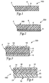
- FIGs. 1-5 illustrate in cross-sectional views (enlarged) five nonlimiting embodiments of conformable magnetic articles in accordance with the present invention.
- FIG. 1 illustrates conformable magnetic article 100, comprising a polymeric binder layer 4 having dispersed therein a plurality of magnetically orientable magnetic particles 6. The combination of organic binder 4 and magnetic particles 6 is referred to herein as magnetic layer 2.
- FIG. 2 represents the conformable magnetic article of FIG. 1 having an adhesive layer 8 with conformable magnetic article 200 having the same magnetic layer 2 as embodiment 100 in FIG. 1.
- Figures 3, 4, and 5 represent pavement marking tapes having irregular surfaces (i.e., the tapes comprise skid-resistant particles, microspheres, or both). Use of these tapes may be beneficial because of ease of manufacturing or to enhance adhesion to the surrounding surfaces.
- FIG. 3 represents an alternative magnetic pavement marking tape within the invention, again showing magnetic layer 2 comprising binder 4, magnetic particles 6, optional adhesive layer 8, and liner layer 10 temporarily adhered to adhesive layer 8.
- Embodiment 300 of FIG. 3 also illustrates a retroreflective and anti-skid layer comprised of a vinyl, epoxy, acidic olefin copolymer or polyurethane elastic support layer 12 which serves to adhere transparent microspheres 14 and irregularly shaped skid-resistant particles 16 to magnetic layer 2. These microsphere and skid-resistant particles may be placed on all sides of the article.
- transparent microspheres 14 or other particles by providing a surface irregularity may prevent the article from sliding around within the traffic-bearing structure.
- Support layer 12 is less thick but generally less inelastic than magnetic layer 2.
- the support layer does not override the desired inelastic deformation properties of the magnetic layer that account for superior durability, and the support layer nevertheless supports the microspheres at the top of the article.
- the thickness of magnetic layer 2 is at least about 1 ⁇ 4 millimeter, more preferably at least about 1 millimeter, but preferably less than 3 millimeters.
- support layer 12 When microspheres are pressed at normal room temperature into a sample of support layer 12 laid on a hard unyielding surface with a pressure that would embed microspheres into magnetic layer 2, the microspheres do not become embedded but remain on the surface of support layer 12 after the pressure has been released.
- support layer 12 has good adhesion to retroreflective elements or other particulate matter to be embedded in it, which assists in holding such particles against penetration into the magnetic layer, and possibly orienting magnetic particles 6 in an undesired direction.
- Vinyl-based polymers polymers that include at least 50 weight percent polymerized vinyl monomer units
- vinyl-based polymers tend to be abrasion resistant which may aid in securing the article within the traffic-bearing surface.
- Support layers based on vinyl polymers are typically plasticized to provide desired flexibility.
- Other support layer materials can be polyurethanes, acid containing olefin copolymers or other such materials known in the art.
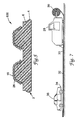
- FIG. 4 illustrates an enlarged cross-sectional view of embodiment 400 of a conformable magnetic pavement-marking tape in accordance with the present invention.
- Embodiment 400 is essentially identical to that of embodiment 300 of FIG. 3 except that the adhesive layer 18 comprises a woven or nonwoven fibrous web 21 embedded in and impregnated by the adhesive layer.
- a stratum 20 of the adhesive layer illustrated in FIG. 4 is disposed between magnetic layer 2 and fibrous web 21, and another stratum 22 of adhesive is disposed on the side of the web opposite from magnetic layer 2 forming the exterior bottom surface of the inventive tape, although there is no requirement that any adhesive be between web 21 and magnetic layer 2.
- a liner material (not illustrated) may be included on adhesive layer 18 opposite magnetic layer 2.
- the fibrous web is preferably contained in the adhesive layer and is sufficiently porous and the fibers sufficiently separated so that the adhesive can saturate, i.e., surround individual fibers of the web.
- the fibrous web if employed, may provide reinforcement or support for the conformance layer.
- Tape embodiment 400 with the fibrous web present, has a tensile strength of at least 0.5 kilogram per centimeter width, and preferably at least 1 kilogram per centimeter width.
- the residual force exhibited by all articles of the invention should be low so as to allow it to remain in good conformity to the irregularities of the traffic-bearing structure layers. This residual force is typically described as creep recovery in penetration mode, as further explained herein.
- the fibrous web is typically impregnated with a liquid version of the adhesive (100% solids or less) for example by passing the web through knife coater.
- a liquid version of the adhesive (100% solids or less) for example by passing the web through knife coater.
- Sufficient adhesive may be applied to the reinforcing web in this manner so that it may be adhered to a magnetic layer; or the magnetic layer may be covered with a layer of adhesive prior to application of the impregnated web, and added adhesive can be applied to form the bottom portion of the adhesive layer.
- FIG. 5 illustrates an enlarged cross-sectional view of embodiment 600, which is an alternate magnetic marking embodiment of the invention.
- Skid particles are adhered only on the side surfaces and a portion of the top surface of the protuberances using an organic binder 26, such as a thermoplastic or thermosetting "particle-bond" material.
- organic binder 26 such as a thermoplastic or thermosetting "particle-bond" material.
- One such binder is a vinyl-based thermoplastic resin including a pigment, as described in US-A-4 117 192.
- suitable particle-bond materials include two-part polyurethanes formed by reacting polycaprolactone diols and triols with derivatives of hexamethylene diisocyanate; epoxy based resins described in US-A-4 248 932; US-A-3 436 359; and US-A-3 580 887; blocked polyurethane compositions as described in US-A-4 530 859; and polyurethane compositions comprised of a moisture-activated curing agent (e.g., an oxazolidine ring) and a polyisocyanate prepolymer.
- Magnetic particles 6 are present in layer 2 as in the other embodiments of the invention.
- the protuberances are generally at least about one millimeter in height, with about one millimeter spacing.
- the conformable articles of the present invention may have nonconformable portions with or without magnetic particles.
- the articles of the invention have a plurality of magnetic particles in a binder which form a conformable magnetic layer. A sufficient amount of magnetic particles are present to provide a magnetic signal through the traffic-bearing structure to a sensor. Typically magnetic particles are non-spherical.
- organic binder for example when the organic binder comprises non-crosslinked elastomeric precursors (see for example US-A-4 490 432), traditional rubber processing methods preferably are used to produce the conformable magnetic layer.
- compounding is performed in some type of heavy duty, batch or continuous, rubber kneading machine, such as a Banbury mixer or twin screw extruder.
- the conformable magnetic layer may be formed by calendering between heavy rolls and then slitting to the desired width, directly by extrusion through a die, or by a combination of such methods. If the extruded material is semi-liquid as it leaves the die, the desired magnetic orientation of the magnetic particles may be produced by exposure to a permanent magnet or electromagnet at the exit of the die. Mechanical working, such as that which occurs during extrusion or calendering, and/or externally applied fields will promote orientation. Orientation enables one to obtain desired magnetic performance. Other methods of preparation and orientation will be apparent to one skilled in the art.
- Elastomer precursor is used herein to describe a polymer which can be crosslinked, vulcanized, or cured to form an elastomer.
- An “elastomer” is a material that can be stretched, to at least about twice its original dimensions without rupture and upon release of the stretching force rapidly returns to substantially its original dimensions.
- Illustrative examples of useful elastomer precursors include acrylonitrile-butadiene polymers, neoprene, polyacrylates, natural rubber, and styrene-butadiene polymers.
- Extender resins preferably halogenated polymers such as chlorinated paraffins, but also hydrocarbon resins, polystyrenes or polycyclodienes, are preferably included with the non-crosslinked elastomer precursor ingredients, and are miscible with, or form a single phase with, the elastomer precursor ingredients.
- the extender resins preferably account for at least 20 weight of the organic components in a conformable layer when using this binder.
- thermoplastic reinforcing polymers are known in the pavement marking art (e.g., polyolefins, vinyl copolymers, polyethers, polyacrylates, styreneacrylonitrile copolymers, polyesters, polyurethanes and cellulose derivatives).
- the conformance layer has two primary components: a ductile thermoplastic polymer and a nonreinforcing magnetic mineral particulate.
- the thermoplastic polymer is a polyolefin. These binders are described generally in US-A-5 194 113.
- Another embodiment of the present invention may utilize a conformability layer comprising microporous thermoplastic polymer.
- Non-magnetic fillers and extenders may be used as desired.
- the desired conformance properties of a material can be indicated by a penetration creep-recovery test (see generally US-A-5 127 973).
- a probe is placed in contact with a sample of the material to be tested, a load placed on the probe, and penetration of the probe into the sample monitored. After a time, the load is removed from the probe and the probe position monitored as the sample is allowed to recover.
- Testing is typically carried out in a helium atmosphere using a thermomechanical analyzer module controlled by a temperature programmer, such as a Perkin Elmer TMS-1 thermomechanical analyzer controlled by a Perkin Elmer DSC-2 temperature programmer.
- the flat-point penetration probe assembly is used, with the probe tip diameter specified (typically 1 millimeter with the Perkin Elmer equipment).
- Samples of the materials to be tested have a thickness of approximately 0.8 millimeter and an area of approximately 3-millimeter-by-3-millimeter. The sample is transferred to a small aluminum pan and placed on the sample platform of the thermomechanical analyzer.
- thermomechanical analyzer A load of one gram is placed on the probe and the probe released and allowed to fall onto the sample. After about 3 to 5 seconds of contact with the sample, the one gram load is removed and the sample allowed to relax. This results in the probe tip resting on the sample in a zero-loading condition.
- the temperature control chamber of the thermomechanical analyzer is raised to surround the sample platform and bring the sample to thermal equilibrium at the desired temperature of the test (generally about room temperature or up to 30°C). The sample is allowed to equilibrate at the test temperature for approximately five minutes with the probe still in contact with the sample surface in a zero-loading condition.
- Data acquisition of the probe position is then begun with the probe still under a load of zero to establish the zero-load baseline.
- a mass of 20 grams is placed on the probe and the probe deflection monitored as it penetrates into the sample.
- the load is allowed to remain on the sample for two minutes, after which the 20-gram mass is removed from the probe to again attain a zero-load condition for the recovery step of the test.
- Sample recovery is monitored for at least two more minutes. The amount of penetration two minutes after the load was applied and the percentage of recovery two minutes after the load is removed are measured from creep-recovery data traces obtained in the experiment.
- a probe having a diameter of 1 millimeter When performing the above test, a probe having a diameter of 1 millimeter generally penetrates at least 0.05 millimeter, and preferably penetrates at least 0.08 millimeter into useful conformance layers.
- the top layer in some embodiments of the invention undergoes a penetration of less than 0.05 millimeter in the described test.
- the conformable layer should recover after removal of the load no more than 65 percent of the distance to which the probe has penetrated, and preferably no more than 50 percent of the penetrated distance.
- the conformable layer is preferably a stretchable or flowable material.
- the conformable layer is preferably capable of being stretched at least 50 percent before break at a strain rate of 0.05 second -1 for a 1 cm wide sample.
- inelastic deformation Another test which may be used to indicate conformability is inelastic deformation.
- articles having a layer characterized by exhibiting, when tested using standard tensile strength testing apparatus, at least 25% inelastic deformation (ID) after being stretched once to 115% of the original sample length have sufficient conformance.
- ID inelastic deformation
- Inelastic deformation may be tested using the following method.
- a test strip (standard strip size for tensile strength testing) is pulled in a tensile strength apparatus (at, for example, a rate of 300%/minute), until it has stretched some predetermined amount, e.g., 15%.
- the deformation is reversed, causing a decrease in tensile stress to zero.
- no force is observed until the sample is again taut.
- the strain at which force is first observed on a second pull is a measure of how much of the first deformation was permanent. This strain divided by the first (e.g., 15%) deformation is defined as the inelastic deformation (ID).
- ID inelastic deformation
- a perfectly elastic material or rubber would have a 0% ID.
- Conformable materials useful in the present invention combine low stress of deformation and ID greater than 25%, preferably greater than 35%, more preferably greater than 50%.
- one skilled in the pavement marking art can generally determine if a particular sample of a conformance layer material will exhibit the desired creep recovery and inelasticity characteristics by simply handling the sample and probing it with a finger. Such "hand" characteristics are often employed in day-to-day testing.
- magnetic material is a composite of particles of a permanent magnetic material dispersed in a matrix of an organic binder. Many types of magnetic particles capable of being remanently magnetized are known to those familiar with the magnetic materials art.
- the major axis length of such particles (defined as the maximum length in any direction) suitable for use in this invention ranges from about 1 millimeter down to about 10 nanometers. The preferred range is from about 200 micrometers down to about 0.1 micrometer.
- the saturation magnetization of the magnetic particles can range from about 10 to about 250 emu/g (electromagnetic units/gram), and is preferably greater than 50 emu/g.
- the coercivity of such particles can range from about 100 to about 20,000 oersteds, more preferably ranging from about 200 to about 5000 oersteds. Particles with coercivities less than about 200 oersteds are too easily accidentally demagnetized, while particles with coercivities greater than 5000 oersteds require relatively expensive equipment to magnetize fully.
- the article of the present invention may comprise sections of alternating polarity along the length of the article.
- One class of high-performance permanent magnet particles are the rare earth-metal alloy type materials.
- examples of the incorporation of such particles into a polymeric binder include US-A-4 497 722, which describes the use of samarium-cobalt alloy particles, and EP-A-260 870 which describes the use of neodymium-iron-boron alloy particles.
- Such particles are not the most preferred for this application, because the alloys are relatively costly; the alloys may experience excessive corrosion under conditions of prolonged outdoor exposure; and the coercivity of such alloys is typically greater than 5000 oersteds.
- metal or metal-alloy permanent magnet particles could be used, but are not the most preferred. They include Alnico (aluminum-nickel-cobalt-iron alloy), iron, iron-carbon, iron-cobalt, iron-cobalt-chromium, iron-cobalt-molybdenum, iron-cobalt-vanadium, copper-nickel-iron, manganese-bismuth, manganese-aluminum, and cobalt-platinum alloys.
- the most preferred magnetic materials are of the class of stable magnetic oxide materials known as the magnetic ferrites.
- One particularly preferred material is the hexagonal phase of the magnetoplumbite structure commonly known as barium hexaferrite, which is generally produced as flat hexagonal platelets. Strontium and lead can substitute in part or completely for the barium, and many other elements can partially substitute for the iron. Thus strontium hexaferrite is also a preferred material.
- Another class of preferred materials is the cubic ferrites, which are sometimes produced as cubic particles, but more often as elongated needle-like, or acicular, particles.
- Examples include magnetite (Fe 3 O 4 ), magnemite or gamma ferric oxide (gamma-Fe 2 O 3 ), intermediates of these two compounds, and cobalt-substituted modifications of the two compounds or of their intermediates. All of these magnetic ferrites are produced in large quantities at relatively low cost and are stable under conditions of prolonged outdoor exposure. Their coercivities fall in the most preferred range of 200 to 5000 oersteds.
- Chromium dioxide is another alternate material which may be useful as a magnetic particle in the invention due to its low Curie temperature, which facilitates thermoremanent magnetization methods.
- the magnetic particles are generally dispersed in the polymeric matrix at a high loading.
- the magnetic particles constitute at least 1 volume percent of the magnetic layer, while it is difficult to include particles in an amount constituting more than about 75 volume percent of the material.
- the conformable magnetic article has a binder comprising at least 30 volume percent of magnetic particles.
- a preferred loading range would be about 30 to 60 volume percent, more preferably from about 45 to about 55 volume percent.
- the particles preferably are substantially domain-size, anisotropic particles, and there preferably is substantially parallel alignment of preferred magnetic axes of a sufficient number of the particles so as to make the magnet material itself anisotropic.
- Ferrites especially barium, lead, and strontium ferrites, generally in a roughly plate-like form having preferred magnetic axes perpendicular to the general planes of the plates, are preferred as the particulate materials.
- other materials having permanent magnetic properties such as iron oxide particles or such as particles of manganese-bismuth or iron protected against oxidation, can also be used.
- the orientation of the magnetic particles may be optimized by physically orienting (e.g. calendering) the particles.
- the magnetic field is about 10 gauss at the surface of the article, 5 gauss at a distance of about 5 cm, 2 gauss at a distance of about 10 cm, and 1 gauss at a distance of about 15 cm.
- the magnetic field strength at the traffic-bearing surface would be approximately 2 gauss, which is believed to be sufficient to be detected by a sensor.
- stronger or weaker magnetic fields may also be produced by the magnetic article, depending on the materials and processes used to make the article.
- the magnetic article may also be provided with protuberances or other topographical features that aid in preventing the article from shifting within the traffic-bearing structure after it has been underlaid.
- the article includes a longitudinally extending tape or strip, in which a multitude of perforations have been formed along the length of the tape. The perforations could allow flow of the traffic-bearing structure material through the strip, providing even greater mechanical anchorage within the traffic-bearing structure itself. In this way, the possibility of flexure and cracking in the traffic-bearing structure may be reduced.
- the magnetic articles of the present invention are underlaid beneath an existing traffic-bearing surface or within a new traffic-bearing surface.
- the conformability feature of the inventive magnetic article is particularly useful when the article is retrofitted to a traffic-bearing structure.
- a portion of an existing traffic-bearing structure is typically ground or cut away, and the debris removed.
- the exposed section of the traffic-bearing structure often is not smooth, and thus the conformability of the magnetic article of the present invention enables the article to bond more securely to the bottom surface of the exposed section.
- the exposed section may then be potted, or filled, with a patching material, and the magnetic article is thus underlaid beneath the traffic-bearing surface.
- Inelasticity is an important feature because traffic-bearing structure, and particularly asphalt cement concrete (commonly known as blacktop, or asphalt), transmit forces applied by vehicles to any object embedded in the traffic-bearing structure.
- an embedded article is elastic relative to the traffic-bearing structure material, the traffic-bearing structure may flex and bounce back toward an applied force, and ultimately crack or break apart, which is manifestly undesirable.
- an irreversibly deformable magnetic article is desirable in the context of this and other embodiments.
- Traffic-bearing structures are typically constructed by laying several courses or layers of materials atop each other.
- a typical asphalt road construction typically includes a crushed rock undercourse on top of which three or four layers of various grades of asphalt may be applied.
- the asphalt layers may be on the order of about 2 to 20 cm thick, and thus the finished traffic-bearing structure is a composite, or laminate, comprising the various layers.
- the magnetic article is applied in a continuous strip in a desired location on the penultimate layer of the traffic-bearing structure, such that the final layer of the traffic-bearing surface covers both the penultimate layer and the magnetic article.
- the magnetic article is underlaid beneath the traffic-bearing surface and protected from vehicular traffic, and yet is sufficiently close to the finished surface of the traffic-bearing surface to permit detection of the magnetic signals by a sensor mounted on a vehicle.
- the article may be underlaid at any depth within the traffic-bearing structure, under any number of layers of the traffic-bearing structure, subject only to the ability of a sensor to receive a magnetic signal from the article.
- the magnetic article may also be underlaid beneath a traffic-bearing surface by providing a base (herein defined as any components the traffic-bearing structure below the traffic-bearing surface layer) for the traffic-bearing structure, positioning the article at a location on or above a portion of the base, and then applying a paving material such as Portland cement concrete (commonly known as concrete) over the article and the base.
- a base herein defined as any components the traffic-bearing structure below the traffic-bearing surface layer
- a paving material such as Portland cement concrete (commonly known as concrete)
- the magnetic article may also underlie a gravel road, either by plowing a trench in an existing gravel road and placing the article under the finished surface of the traffic-bearing structure, or by installing the article on the undercourse of a new gravel road prior to the application of the final layer(s) of that traffic-bearing structure.
- paver bricks may be used as the traffic-bearing structure material and be laid over the prepared baselayer .
- the continuous magnetic article of the present invention may be applied to the traffic-bearing structure either manually, or by a machine.
- the machine may travel ahead of a paving machine, or may be mounted at the leading end of the paving machine, such that the continuous magnetic article is applied to the traffic-bearing structure at some time prior to the application of the final layer or layers of the traffic-bearing structure.
- the magnetic articles of the present invention may be installed as part of a traffic-bearing structure using any one of a variety of apparatus, such as human pushable dispensers, "behind a truck” types of dispensers, and "built into a truck” types of dispensers.
- apparatus such as human pushable dispensers, "behind a truck” types of dispensers, and "built into a truck” types of dispensers.
- US-A-4 030 958 discloses a suitable behind a truck type dispenser for applying the articles of the invention in the form of adhesive-backed tapes to a surface
- US-A-4 623 280 discloses a manual-tape applicator.
- a further layer of the traffic-bearing structure material is applied to underlay the article beneath the top surface of the traffic-bearing structure.
- the conformable magnetic articles of the present invention may be underlaid at various depths.
- the invention also provides a system for guiding vehicles or mobile objects traveling on a roadway, through a warehouse, and the like.
- the primary components of the systems of the invention are the conformable magnetic articles underlaid beneath a traffic-bearing surface of the invention, and a system to detect the magnetic field from the article.
- a typical sensor system includes a sensor device and a guidance device.
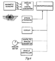
- a typical lateral position indicator system of the invention suitable for use in guiding a human operated vehicle is illustrated in FIG. 6.
- the inventive magnetic article also is unpowered, meaning that it does not require an outside power source either to send or receive a signal.
- the present invention is distinguishable from powered embedded articles such as those that are typically used to determine whether a vehicle on a roadway is stopped at an intersection, such as at a red light.
- Embedded sensors of this type are further distinguishable from the present invention in that the former requires electrical power, whereas the latter is an unpowered magnetic field source.
- the unpowered magnetic article of the present invention also requires less installation time and less maintenance, costs nothing to operate, and may be used in remote locations where a power supply is not readily available.
- the unpowered magnetic article of this invention provides several advantages over conventional embedded powered articles.
- sensors and transducers are available to convert the magnetic signal from the articles of the invention into an electrical signal suitable for further processing.
- Illustrative examples of such sensors include flux-gate magnetometers, Hall effect sensors, and solid-state magnetoresistive (MR) sensors.
- the sensor is mounted in a position suitable for measuring the fields produced by the underlaid tape of the present invention.
- Magnetic sensors attached to the vehicle may determine the field in one, two, or all three directions.
- the signal from one sensor or a mathematical combination of two or three field components may be used to compute a signal that can be related to lateral distance of a vehicle from the inventive articles.
- additional information can be encoded. For example, information about the direction and radius of an upcoming curve in the road or about the slope of an approaching upgrade or downgrade could be used for feed-forward control of the lateral position and speed of the vehicle. As part of a vehicle navigation system, location codes could be given.
- Illustrative examples of indicating means include at least one horn, gauge, whistle, electrical stimulation, LCD, CRT, light, combination of these, and the like. One or more indicating means may be desired in a particular situation.
- An electronic control means may be used as a guidance means in the present invention.
- a conformable magnetic article of the invention was made by compounding the following in a Banbury-type internal mixer to thoroughly mix the ingredients.
- the temperature of the mix reached 146°C the mix was dropped from the mixer onto a two roll rubber mill. The material was sheeted off the rubber mill and fed through a two-roll calender to yield a sheet of material having a thickness of approximately 1.4 mm.
- the sheet of material was embossed according to the process described in US-A-5 227 221 (col. 2, lines 47-65) to provide a conformable magnetic sheet having a plurality of protrusions projecting from one of its major surfaces.
- the embossed sheet had a thickness of about 0.5 mm in the valleys between the protrusions, and a thickness of about 1.6 mm at the protrusions.
- a discontinuous layer of liquid particle bond material was applied to the top and sides of the protrusions of the embossed sheet using the process described in US-A-5 227 221.
- the particle bond material was the same as the polyurethane bead bond of US-A-5 227 221 (col.
- the surface of the particle bond material coated protrusions was sprinkled with durable black spheroidal anti-skid particles of the type available from Carbo Ceramics of New Iberia, Louisiana, under the designations CARBOLITE and CARBOPROP.
- the particles were applied so as to partially embed them in the liquid particle bond material.
- the liquid particle bond material was solidified as described in US-A-5 227 221 by passing the sheet through an oven at a temperature of about 175°C for approximately 10 minutes of residence time.
- a layer of rubber resin pressure sensitive adhesive with a thickness of about 125 micrometers was laminated to the bottom side of the sheet.
- the sheet had a hand characteristic of conformable pavement marking tapes and quite similar to those of STAMARKTM 380 Series pavement marking tape and STAMARKTM 385 Series Non-Reflective Joint Cover Tape available from Minnesota Mining and Manufacturing Co. (3M) of St. Paul, Minnesota.
- the sheet was visually similar to STAMARKTM 385 except that the non-particle coated regions between the projections were dark purplish-brown in color instead of black
- Example 2 This sample was prepared as disclosed in Example 1, except that the coating of a particle bond material and anti-skid particles were omitted.
- the sample had a hand characteristic similar to Example 1.
- the sample was suitable for being underlaid beneath a layer of paving material.
- This example was prepared in the same manner as was Example 2, except that the calendered sheet material was not embossed.
- the sample had a hand characteristic similar to conformable sheet materials disclosed in US-A-4 490 432.
- the sample was suitable for being underlaid beneath a layer of paving material.
- Example 1 The sheet material of Example 1 was magnetized by passing the sheet between the magnetic poles of a permanent magnet assembly.
- the magnetizing field was about 10,000 gauss (1 tesla), and the resulting permanent magnetization of the sheet material was about 120 electromagnetic units per cubic centimeter (120 kilo-amperes per meter).
- Example 1 The sheet material of Example 1 was magnetized by passing a web of the sheet between the magnetic poles of an electromagnet assembly.
- the magnetizing field was about 10,000 gauss (1 tesla).
- the resulting permanent magnetization of the sheet material was about 120 electromagnetic units per cubic centimeter (120 kilo-amperes per meter).
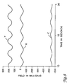
- a length encoder measured the length of web passing between the poles of the electromagnet. After a fixed length of tape web, typically between 0.9 and 3.0 meters, had passed between the poles, the direction of current flow was automatically reversed, thus reversing the direction of magnetization of the tape.
- the magnetic field of the sheet of this Example was measured near the top surface of the sheet as shown in the following Table. Distance above sheet (cm) Magnetic field strength (gauss) 0 (surface measurement) 10 5 5 10 2 15 1
- a magnetic sheet material could be made following the steps used to produce the article of Example 1, with the additional step of punching an array of holes completely through the sheet.
- the holes should be large enough, preferably on the order of 5 mm or more, or more preferably 8 mm or more, in diameter so as to allow flow of roadway paving material through the sheet to contact and bond with the underlying roadway base.
- the article could be magnetized following processes such as those used in Examples 4 and 5.
- a layer of asphalt paving compound was applied to the gravel undercourse of a roadbed and tamped.
- a roll of sheet material prepared in accordance with Example 6 was applied to the top surface of the layer of asphalt while the asphalt was still hot (about 65 to 95°C) and tamped into place by having a person walk on the sheet.
- the sheet measured 10.2 cm in width and 55 m in length.
- the sheet had a magnetization pattern of alternating north and south poles directed upward with a field direction change every 2.13 m.
- a layer of asphalt concrete cement paving material was paved over the magnetic strip and underlying base to yield an underlaid conformable magnetic article of the invention.
- the layer of asphalt was about 4 cm thick, and the temperature of the applied material was about 120°C.
- the magnetic field emanating from the strip was detectable through the layer of asphalt by means of a simple compass or pivoted bar magnet, as well as by various types of magnetometers.
- the net magnetic field strength, corrected for the earth's field, above the centerline of the strip was 6 gauss (600 microtesla), as determined with a Model 4048 hand-held digital gauss/tesla meter, available from F.W. Bell, Inc. of Orlando, Florida.
- the magnetic strip of Example 7 was installed beneath pavement with a longitudinal orientation of the strip running in a generally east/west direction and north/south direction.
- the magnetic field of the underlaid magnetic strip was measured at a height of 30.5 cm above the pavement surface at a range of lateral distances of from 4 cm to 1.2 m while traveling along the length of the underlaid strip.
- the speed of travel was approximately 1.07 m/s in the easterly direction.
- the ambient air temperature was approximately 24°C and the pavement surface temperature was approximately 35°C.
- a graph of representative data from measurements made in each of the X, Y, and Z directions while traveling at a lateral distance of 0.6 m south of the strip is shown in Figure 8.
- the X direction is the direction of travel (east).
- the Y direction is transverse to the strip (north).
- the Z direction is vertical elevation (upward).
- Amplitudes of magnetic field strength were estimated from the data for each of several runs at lateral distances of from 4 cm to 1.2 m by measuring the peak to peak amplitude of the waveform and dividing by two to account for pole reversal for each direction X, Y, and Z for measurement runs made at each distance.
- the data are shown in the following table.
- Readings were taken using a F.W. Bell gauss meter model 4048 before the final 4 cm topcoat of asphalt was laid. The readings were taken about 2.5 cm above the surface, centered over the tape, away from the field transitions, and normal to the tape or perpendicular to the field. The surface temperature was about 95°C. The average reading was 7 gauss ( ⁇ 10 percent).
- the surface temperature was about 20°C. Readings were taken from both the east-west and the north-south strips. The average reading was 3.8 gauss. Visual observations: no noticeable defects in the surface where the tape was underlaid.
- the surface temperature was about 20°C. Readings were taken from both the east-west and the north-south strips. The average reading was 3.8 gauss. Visual observations: cracked asphalt, but not along the surface where the tape was underlaid; in one instance, the asphalt cracked perpendicular to the direction in which the tape was underlaid beneath the surface.
- Example 4 The sheet material of Example 4 was underlaid within a traffic-bearing surface of a road in June 1996.
- the tape was laid over the 3rd layer of asphalt (surface temperature 111°F (44°C)) using a MHTA-1 Manual Highway Tape Applicator available from 3M.
- MHTA-1 Manual Highway Tape Applicator available from 3M.
- three single passes were made with a RTC-2 Roller-Tamper Cart with a 200 lb. (90.8 kg) weight (available from 3M) to tamp the tape into place.
- a tack layer of oil was applied and allowed to "dry”.
- a final layer of asphalt (about 4 cm thick)was placed over the tape.
- Each tape was 0.75 miles (1.2 km). A reading was taken using a gauss meter at approximately 2.5 cm above the top layer of asphalt and measured 2.9 gauss at a surface temperature of about 95°C.
Claims (28)
- Article magnétique déformable (100) à appliquer sous une surface réservée à la circulation pour envoyer un signal magnétique à un capteur se déplaçant sur la surface réservée à la circulation, ledit article magnétique comprenant au moins une couche magnétique déformable (2) comprenant un liant (4) et au moins 30 pour cent en volume de particules magnétiques (6) dispersées à l'intérieur du liant pour envoyer ledit signal magnétique à un capteur à travers la structure réservée à la circulation.
- Article magnétique selon la revendication 1, dans lequel ladite couche magnétique déformable (2) a une longueur initiale de spécimen et est caractérisée en ce qu'elle présente, lorsqu'elle est testée avant de la faire adhérer à la surface d'un substrat au moins 25 pour cent de déformation inélastique après avoir été étirée une fois de 115 pour cent de la longueur initiale du spécimen.
- Article magnétique selon la revendication 1, dans lequel ledit article est pratiquement inélastique.
- Article magnétique selon la revendication 1, dans lequel ledit article est perforé dans sa longueur.
- Article magnétique selon la revendication 1, dans lequel ledit article comprend des sections de polarités alternant dans la longueur de l'article.
- Article magnétique selon la revendication 1, dans lequel ledit article magnétique comprend en outre une couche d'adhésif sensible à la pression (8) appliquée sur une surface principale de l'article.
- Système de guidage de véhicules ou d'objets mobiles se déplaçant sur une structure réservée à la circulation, comprenant :(a) au moins un article magnétique déformable (100) selon la revendication 1 et(b) un capteur pour circuler sur la surface réservée à la circulation, ledit capteur comprenant un moyen de détection du signal magnétique à travers la structure réservée à la circulation.
- Système selon la revendication 7, dans lequel ladite couche déformable (2) a une longueur initiale de spécimen et est caractérisée en ce qu'elle présente, lorsqu'elle est testée avant de la faire adhérer à la surface d'un substrat au moins 25 pour cent de déformation inélastique après avoir été étirée une fois de 115 pour cent de la longueur initiale du spécimen.
- Système selon la revendication 7, dans lequel ledit article magnétique est pratiquement inélastique.
- Système selon la revendication 7, dans lequel ledit article magnétique est perforé dans sa longueur.
- Système selon la revendication 7, dans lequel ledit article comprend des sections de polarités alternant dans sa longueur.
- Système selon la revendication 7, dans lequel ledit capteur (34) est monté sur un véhicule (36) adapté pour se déplacer sur la surface réservée à la circulation (33).
- Système selon la revendication 7, dans lequel ledit article magnétique comprend en outre une couche d'adhésif sensible à la pression (8) appliquée sur une surface principale de l'article.
- Système de guidage de véhicules ou d'objets mobiles se déplaçant sur une structure réservée à la circulation, comprenant :(a) au moins une structure réservée à la circulation comprenant au moins deux couches de matériau ;(b) un article magnétique déformable (100) selon la revendication 1 appliqué sous la surface supérieure de la dite structure réservée à la circulation entre deux desdites couches, ledit article est adapté pour envoyer un signal magnétique à un capteur se déplaçant sur la surface réservée à la circulation ; et(c) un capteur pour circuler sur la surface réservée à la circulation, ledit capteur comprenant un moyen de détection du signal magnétique à travers la structure réservée à la circulation.
- Système selon la revendication 14, dans lequel ladite couche déformable (2) a une longueur initiale de spécimen et est caractérisée en ce qu'elle présente, lorsqu'elle est testée avant de la faire adhérer à la surface d'un substrat au moins 25 pour cent de déformation inélastique après avoir été étirée une fois de 115 pour cent de la longueur initiale du spécimen.
- Système selon la revendication 14, dans lequel ledit article magnétique est pratiquement inélastique.
- Système selon la revendication 14, dans lequel ledit article magnétique est perforé dans sa longueur.
- Système selon la revendication 14, dans lequel ledit article magnétique comprend des sections de polarités alternant dans sa longueur.
- Système selon la revendication 14, dans lequel capteur est monté sur un véhicule adapté pour circuler sur ladite surface réservée à la circulation.
- Système selon la revendication 14, dans lequel ladite structure réservée à la circulation comprend du béton de ciment au bitume et dans lequel lesdites deux couches sont les deux couches les plus externes de ladite structure réservée à la circulation.
- Système selon la revendication 14, dans lequel ledit article magnétique comprend en outre une couche d'adhésif sensible à la pression (8) appliquée sur une surface principale de l'article.
- Procédé d'obtention d'un système de guidage pour une structure existante réservée à la circulation comprenant les étapes consistant :(a) à retirer une certaine quantité de matériau de la structure réservée à la circulation pour obtenir une dépression ;(b) à placer à l'intérieur de la dépression un article magnétique déformable (100) selon la revendication 1 adapté pour envoyer un signal magnétique à un capteur se déplaçant sur la surface réservée à la circulation et(c) à placer une quantité suffisante d'un matériau à l'intérieur de la dépression pour enrober complètement l'article magnétique à l'intérieur du matériau.
- Procédé selon la revendication 22, dans lequel ledit article magnétique comprend en outre une couche d'adhésif sensible à la pression (8) appliquée sur une surface principale de l'article.
- Procédé selon la revendication 22, dans lequel ledit article magnétique est fixé à l'intérieur de la dépression par au moins un fixateur mécanique avant l'étape (c).
- Procédé d'obtention d'un système de guidage pour une structure réservée à la circulation, comprenant les étapes consistant :(a) à préparer une base de structure réservée à la circulation ;(b) à préparer un article magnétique déformable (100) selon la revendication 1 adapté pour envoyer un signal magnétique à un capteur se déplaçant sur la surface réservée à la circulation(c) à positionner l'article magnétique à un endroit sur ou au-dessus d'une portion de la base de structure réservée à la circulation ; et(d) à appliquer un matériau de structure réservée à la circulation sur l'article magnétique et sur la base de structure réservée à la circulation.
- Procédé selon la revendication 25, dans lequel les matériaux de structure réservée à la circulation sont choisis parmi le béton de ciment au bitume, le ciment Portland, et le gravier.
- Procédé selon la revendication 25, dans lequel ledit article magnétique comprend en outre une couche d'adhésif sensible à la pression appliqué sur une surface principale de l'article.
- Procédé selon la revendication 25, dans lequel ledit article magnétique est fixé à la structure réservée à la circulation par au moins un fixateur mécanique avant l'étape (d).
Applications Claiming Priority (3)
| Application Number | Priority Date | Filing Date | Title |
|---|---|---|---|
| US555195P | 1995-10-18 | 1995-10-18 | |
| US5551P | 1995-10-18 | ||
| PCT/US1996/016395 WO1997014850A1 (fr) | 1995-10-18 | 1996-10-11 | Articles magnetiques deformables appliques sous des couches de roulement de chaussees |
Publications (2)
| Publication Number | Publication Date |
|---|---|
| EP0856088A1 EP0856088A1 (fr) | 1998-08-05 |
| EP0856088B1 true EP0856088B1 (fr) | 2000-12-13 |
Family
ID=21716437
Family Applications (1)
| Application Number | Title | Priority Date | Filing Date |
|---|---|---|---|
| EP96937681A Expired - Lifetime EP0856088B1 (fr) | 1995-10-18 | 1996-10-11 | Articles magnetiques deformables appliques sous des couches de roulement de chaussees |
Country Status (13)
| Country | Link |
|---|---|
| US (1) | US5853846A (fr) |
| EP (1) | EP0856088B1 (fr) |
| JP (1) | JP3706143B2 (fr) |
| KR (1) | KR19990064330A (fr) |
| CN (1) | CN1200158A (fr) |
| AT (1) | ATE198086T1 (fr) |
| AU (1) | AU699652B2 (fr) |
| CA (1) | CA2232873C (fr) |
| DE (1) | DE69611250T2 (fr) |
| DK (1) | DK0856088T3 (fr) |
| ES (1) | ES2152570T3 (fr) |
| NO (1) | NO981755L (fr) |
| WO (1) | WO1997014850A1 (fr) |
Families Citing this family (64)
| Publication number | Priority date | Publication date | Assignee | Title |
|---|---|---|---|---|
| JP3759282B2 (ja) | 1997-04-23 | 2006-03-22 | 本田技研工業株式会社 | 自動走行車 |
| NL1008708C2 (nl) * | 1998-03-25 | 1999-01-12 | Tamar Vanessa Grahmbeek | Werkwijze voor het aanbrengen van geleidelijnen voor visueel gehandicapten, evenals een mal bestemd voor toepassing van de werkwijze. |
| US6274939B1 (en) * | 1998-09-11 | 2001-08-14 | American Electronic Components | Resin ceramic compositions having magnetic properties |
| CA2366105A1 (fr) * | 1999-06-08 | 2000-12-14 | Remington Products Company | Polymeres flexibles magnetiquement actifs |
| US6437561B1 (en) | 1999-11-17 | 2002-08-20 | 3M Innovative Properties Company | System for determining the position of an object with respect to a magnetic field sources |
| JP3638847B2 (ja) * | 2000-02-02 | 2005-04-13 | ユニ・チャーム株式会社 | 吸収性物品の表面シートとその製造方法 |
| CA2337973A1 (fr) * | 2000-03-22 | 2001-09-22 | Illinois Tool Works Inc. | Panneaux antiderapants resistants aux intemperies |
| US6345217B1 (en) * | 2000-03-31 | 2002-02-05 | Rapistan Systems Advertising Corp. | Automated guided vehicle (AGV) with bipolar magnet sensing |
| US6476113B1 (en) | 2000-06-07 | 2002-11-05 | Remington Products Company | Magnetically active flexible polymers |
| US6468942B1 (en) * | 2000-11-16 | 2002-10-22 | John J. Sansalone | Absorptive-filtration media for the capture of waterborne or airborne constituents |
| US7341661B2 (en) * | 2000-11-16 | 2008-03-11 | Unit Process Technologies, L.L.C. | Clarification and sorptive-filtration system for the capture of constituents and particulate matter in liquids and gases |
| US6600418B2 (en) | 2000-12-12 | 2003-07-29 | 3M Innovative Properties Company | Object tracking and management system and method using radio-frequency identification tags |
| US6650815B2 (en) | 2000-12-27 | 2003-11-18 | Corning Incorporated | Optical fiber encoded with data signal |
| US6861134B1 (en) | 2001-04-02 | 2005-03-01 | Omnova Solutions Inc. | Retroreflective articles of nanoporous construction and method for the manufacture thereof |
| US6772062B2 (en) | 2001-05-31 | 2004-08-03 | The Regents Of The University Of California | Intelligent ultra high speed distributed sensing system and method for sensing roadway markers for intelligent vehicle guidance and control |
| US20030012599A1 (en) * | 2001-06-29 | 2003-01-16 | Magnus Wallgren | Markings on roads with a fixed road surface, such as asphalt, concrete or the like for motor vehicles |
| US7169831B2 (en) * | 2001-09-27 | 2007-01-30 | 3M Innovative Properties Company | Pavement marking composition comprising ceramic fibers |
| US6592288B2 (en) | 2001-10-18 | 2003-07-15 | Joong H. Chun | High-traction anti-icing roadway cover system |
| US6669089B2 (en) | 2001-11-12 | 2003-12-30 | 3M Innovative Properties Co | Radio frequency identification systems for asset tracking |
| US20030123930A1 (en) | 2001-12-31 | 2003-07-03 | Jacobs Gregory F. | Matrix element magnetic pavement marker and method of making same |
| AU2004201726B9 (en) * | 2002-11-25 | 2006-11-16 | Illinois Tool Works Inc. | Collated road marker assembly, and system and method for automatically applying collated road markers to roadway surfaces |
| US6896444B2 (en) * | 2002-11-25 | 2005-05-24 | Illinois Tool Works Inc. | Collated road marker assembly, and system and method for automatically applying collated road markers to roadway surfaces |
| US6832871B2 (en) * | 2002-11-25 | 2004-12-21 | Illinois Tool Works Inc. | Collated road marker assembly, and system and method for automatically applying collated road markers to roadway surfaces |
| US20050265783A1 (en) * | 2004-02-01 | 2005-12-01 | Nehemia Amir | Acoustic modulation of road surface |
| FR2871274B1 (fr) * | 2004-06-02 | 2007-03-16 | Centre Nat Rech Scient Cnrse | Systeme d'aide a la conduite pour la cooperation mobile infrastructure |
| US7839271B2 (en) | 2004-06-02 | 2010-11-23 | Centre National De La Recherche Scientifique -Cnrs- | Driving assistance system for interaction between a mobile element and an infrastructure |
| US20070077119A1 (en) * | 2005-10-05 | 2007-04-05 | Northey Paul J | Optically active sheets including a mark indicating a preferred sheet orientation |
| WO2007071215A1 (fr) * | 2005-12-19 | 2007-06-28 | Karl Salzmann | Installation a induction |
| US20080084634A1 (en) * | 2006-09-22 | 2008-04-10 | Board Of Regents Of The Nevada System Of Higher Education On Behalf Of The University Nevada | Devices and methods for storing data |
| US7950587B2 (en) * | 2006-09-22 | 2011-05-31 | The Board of Regents of the Nevada System of Higher Education on behalf of the University of Reno, Nevada | Devices and methods for storing data |
| EP2192233A1 (fr) * | 2008-11-27 | 2010-06-02 | Sika Technology AG | Methode pour rendre étanche une voie de circulation |
| FR2949794A1 (fr) * | 2009-09-09 | 2011-03-11 | Eurovia | Produit de marquage eliminable sur commande, en particulier de marquage routier, et son procede de mise en oeuvre |
| KR101376076B1 (ko) * | 2012-08-09 | 2014-03-19 | 한국수력원자력 주식회사 | 노외 노심용융물 냉각설비 희생 콘크리트 조성물 및 이의 제조방법 |
| WO2014082821A1 (fr) * | 2012-11-28 | 2014-06-05 | Evonik Industries Ag | Nouveaux marquages routiers facilitant la perception de l'environnement de véhicules |
| DE102013206116A1 (de) * | 2013-04-08 | 2014-10-09 | Evonik Industries Ag | Neuartige Straßenmarkierungen zur Unterstützung der Umfeldwahrnehmung von Fahrzeugen |
| JP2014211014A (ja) * | 2013-04-17 | 2014-11-13 | Npo法人日本防災環境 | 標示材の敷設方法 |
| US10208439B2 (en) * | 2014-08-14 | 2019-02-19 | Brite-Line Technologies, Llc | Pavement marking tape with widely-distributed, multi-edged relief features for improved retroreflectivity |
| US9892296B2 (en) | 2014-11-12 | 2018-02-13 | Joseph E. Kovarik | Method and system for autonomous vehicles |
| CN107849848B (zh) * | 2015-03-27 | 2021-06-08 | 宝山控股有限责任公司 | 用于磁性表面覆盖物的系统、方法和设备 |
| RU2020106174A (ru) | 2015-03-27 | 2020-04-24 | Голконда Холдингз Ллк | Система и способ для магнитных покрытий поверхностей |
| EP3095914B1 (fr) * | 2015-05-20 | 2021-01-27 | Sika Technology AG | Procédé de production d'une structure routière |
| CN104911982B (zh) * | 2015-06-25 | 2017-04-05 | 苏交科集团股份有限公司 | 一种基于磁性分析技术的路面病害检测方法 |
| JP2017078909A (ja) * | 2015-10-19 | 2017-04-27 | 愛知製鋼株式会社 | 磁気マーカ及び磁気マーカ検出システム |
| JP6355607B2 (ja) | 2015-10-19 | 2018-07-11 | 愛知製鋼株式会社 | 磁気マーカ及び磁気マーカ検出システム |
| CN105528896A (zh) * | 2016-01-15 | 2016-04-27 | 辽宁金洋集团信息技术有限公司 | 柔性表贴封装型磁感应传感器 |
| EP3415691A4 (fr) | 2016-02-10 | 2019-10-09 | Aichi Steel Corporation | Procédé d'installation de marqueur magnétique et système d'engin de chantier |
| CN109074731B (zh) * | 2016-04-28 | 2021-08-27 | 爱知制钢株式会社 | 磁性标识器及驾驶支援系统 |
| JP7012421B2 (ja) * | 2016-06-17 | 2022-01-28 | 愛知製鋼株式会社 | 磁気マーカ及びマーカシステム |
| EP4220263A1 (fr) | 2016-07-18 | 2023-08-02 | Corning Research & Development Corporation | Système de câblage de distribution |
| JP6928306B2 (ja) * | 2017-03-28 | 2021-09-01 | 愛知製鋼株式会社 | 磁気マーカの施工方法及び作業システム |
| WO2018190742A1 (fr) * | 2017-04-13 | 2018-10-18 | Александр Вячеславович ФИЛИППОВ | Procédé de fabrication d'un marquage routier à fonction d'orientation |
| US10127462B1 (en) * | 2017-05-09 | 2018-11-13 | Toyota Research Institute, Inc. | Systems and methods for detecting markers on a roadway |
| US10612199B2 (en) | 2017-05-09 | 2020-04-07 | Toyota Research Institute, Inc. | Systems and methods for roadway fingerprinting |
| US10571280B2 (en) | 2017-05-09 | 2020-02-25 | Toyota Research Institute, Inc. | Systems and methods for localizing a vehicle using a roadway signature |
| WO2019070811A1 (fr) | 2017-10-03 | 2019-04-11 | Corning Research & Development Corporation | Ruban de câblage de distribution, système et dispositif d'application de ruban |
| SG11202007940WA (en) * | 2018-03-01 | 2020-09-29 | Autonotech Pte Ltd | A method and apparatus for laying paint indicia on a road surface and a method for transmitting information to vehicles |
| JP7363775B2 (ja) * | 2018-04-27 | 2023-10-18 | 日本ゼオン株式会社 | 標示構造、並びに、路面標示、道路付属物および建造物 |
| JP7151191B2 (ja) * | 2018-06-11 | 2022-10-12 | 愛知製鋼株式会社 | 磁気マーカ |
| JP7151192B2 (ja) * | 2018-06-11 | 2022-10-12 | 愛知製鋼株式会社 | 磁気マーカの施工方法 |
| CN108867256B (zh) * | 2018-07-27 | 2020-10-09 | 徐州徐工养护机械有限公司 | 一种基于can总线的粉料撒布车控制系统 |
| US11467324B2 (en) | 2018-10-26 | 2022-10-11 | Tundra Composits, LLC | Complex retroreflective bead |
| WO2020112444A1 (fr) | 2018-11-30 | 2020-06-04 | Corning Research & Development Corporation | Dispositif d'application de bande de câblage de distribution avec caméra d'endoscope pour l'enregistrement d'un câble et d'une bande de câblage |
| JP7268498B2 (ja) * | 2019-06-24 | 2023-05-08 | 愛知製鋼株式会社 | 磁気マーカ及び磁気マーカの利用方法 |
| US20210381177A1 (en) * | 2020-06-08 | 2021-12-09 | Jeongseok Chemical Corporation | Apparatus and Method of Applying Magnetic Pattern to Lanes with Magnetic Paint |
Citations (1)
| Publication number | Priority date | Publication date | Assignee | Title |
|---|---|---|---|---|
| WO1996016231A1 (fr) * | 1994-11-17 | 1996-05-30 | Minnesota Mining And Manufacturing Company | Articles magnetiques conformables pour des surfaces destinees a la circulation |
Family Cites Families (50)
| Publication number | Priority date | Publication date | Assignee | Title |
|---|---|---|---|---|
| US1803288A (en) * | 1926-07-23 | 1931-04-28 | Adler Safety Control Company | Automatic speed-control mechanism for automobiles |
| US1803289A (en) * | 1926-07-28 | 1931-04-28 | Adler Safety Control Company | System for automatically controlling the speed of automobiles |
| US1803290A (en) * | 1926-07-31 | 1931-04-28 | Adler Safety Control Company | Trackless-highway control system for automobiles |
| US1803291A (en) * | 1926-11-30 | 1931-04-28 | Adler Safety Control Company | Highway control mechanism for automobiles |
| US1886720A (en) * | 1927-01-24 | 1932-11-08 | Rubber Products Corp | Road marker and method of placing the same in alpha pavement |
| US1803292A (en) * | 1927-11-21 | 1931-04-28 | Adler Safety Control Company | Automatic signal for automobiles |
| US2634659A (en) * | 1950-05-25 | 1953-04-14 | John Hagan | Snow removal construction |
| US3359152A (en) * | 1958-07-15 | 1967-12-19 | Leyman Corp | Machinable anisotropic magnet |
| US2999275A (en) * | 1958-07-15 | 1961-09-12 | Leyman Corp | Mechanical orientation of magnetically anisotropic particles |
| US3179918A (en) * | 1959-02-24 | 1965-04-20 | Raymond W Hoeppel | Vehicle speed limiting and control system |
| US3493923A (en) * | 1967-06-09 | 1970-02-03 | Gen Motors Corp | Road driver communication system utilizing hall cell sensor |
| US3575255A (en) * | 1968-10-11 | 1971-04-20 | Minnesota Mining & Mfg | Automobile guidance system |
| US3609678A (en) * | 1969-04-28 | 1971-09-28 | Minnesota Mining & Mfg | Magnetized means for providing control information to moving vehicles |
| US3668624A (en) * | 1969-11-20 | 1972-06-06 | Novatek Inc | Method and apparatus for vehicle control and guidance |
| US3642087A (en) * | 1970-10-09 | 1972-02-15 | Pentron Electronics Corp | Automatic guidance system |
| US3787839A (en) * | 1970-11-12 | 1974-01-22 | Minnesota Mining & Mfg | Magnetic viewer device having movable anisotropic elements |
| US3714625A (en) * | 1971-03-30 | 1973-01-30 | Minnesota Mining & Mfg | Vehicle guidance track of transverse extent |
| US3753223A (en) * | 1971-08-16 | 1973-08-14 | Minnesota Mining & Mfg | System to determine the directional mode of travel of vehicles on a roadway |
| US3878367A (en) * | 1973-05-02 | 1975-04-15 | Minnesota Mining & Mfg | Magnetic security document and method for making same |
| US3927393A (en) * | 1973-05-02 | 1975-12-16 | Minnesota Mining & Mfg | Magnetic record medium authentication system |
| IT1022451B (it) * | 1974-09-30 | 1978-03-20 | Eigenmann Ludwig | Striscia prefabbricata per segnale tica stradale orizzontale e metodo per la sua prefabbricazione |
| US4090662A (en) * | 1975-05-28 | 1978-05-23 | Minnesota Mining And Manufacturing Company | Tamperproof magnetically readable label |
| US4117192A (en) * | 1976-02-17 | 1978-09-26 | Minnesota Mining And Manufacturing Company | Deformable retroreflective pavement-marking sheet material |
| ZA755471B (en) * | 1976-02-28 | 1977-05-25 | W Richter | Improvements in automatic guidance |
| US4185265A (en) * | 1977-06-09 | 1980-01-22 | Cincinnati Electronics Corporation | Vehicular magnetic coded signalling apparatus |
| US4239415A (en) * | 1978-11-06 | 1980-12-16 | Blikken Wendell A | Method of installing magnetic sensor loops in a multiple lane highway |
| US4234264A (en) * | 1979-01-02 | 1980-11-18 | Baldi Michael O | Multi-directional marking device of the type to be used on pavement surfaces |
| US4312601A (en) * | 1979-02-26 | 1982-01-26 | The Secretary Of State For Defence In Her Britannic Majesty's Government Of The United Kingdom Of Great Britain And Northern Ireland | Fascines |
| US4248932A (en) * | 1979-06-14 | 1981-02-03 | Minnesota Mining And Manufacturing Company | Extended-life pavement-marking sheet material |
| US4299874A (en) * | 1980-03-31 | 1981-11-10 | Minnesota Mining And Manufacturing Company | Removable pavement-marking sheet material |
| US4490432A (en) * | 1982-04-23 | 1984-12-25 | Minnesota Mining And Manufacturing Company | Reinforced pavement-marking sheet material |
| US4388359A (en) * | 1982-04-23 | 1983-06-14 | Minnesota Mining And Manufacturing Company | Embossed pavement-marking sheet material |
| US4534673A (en) * | 1983-04-11 | 1985-08-13 | Minnesota Mining And Manufacturing Company | Elastomeric pavement marker |
| CA1215223A (fr) * | 1983-07-04 | 1986-12-16 | Tokuji Abe | Compose pour matiere plastique aimantee |
| EP0135740A3 (fr) * | 1983-08-05 | 1987-09-30 | Ludwig Dr. Eigenmann | Système à codeur et décodeur pour fournir des informations au conducteur de véhicule |
| DE3444783C2 (de) * | 1984-12-06 | 1986-10-23 | Mannesmann AG, 4000 Düsseldorf | Zuschlagstoff für den Straßenbau |
| CA1311160C (fr) * | 1985-06-13 | 1992-12-08 | Asok Sengupta | Materiau de marquage pour carrefour |
| FR2610427B1 (fr) * | 1987-02-04 | 1995-09-29 | Protee | Systeme et procede de controle de la marche d'un vehicule autonome |
| US4988541A (en) * | 1988-06-09 | 1991-01-29 | Minnesota Mining And Manufacturing Company | Process for making retroreflector sheet |
| US5227221A (en) * | 1988-06-09 | 1993-07-13 | Minnesota Mining And Manufacturing Company | Patterned skid preventative sheet |
| CA1307971C (fr) * | 1988-06-09 | 1992-09-29 | Thomas Peter Hedblom | Materiau de marquage de chaussees |
| US4988555A (en) * | 1988-06-09 | 1991-01-29 | Minnesota Mining And Manufacturing Company | Patterned pavement marking |
| US5316406A (en) * | 1989-02-10 | 1994-05-31 | Briteline Industries, Inc. | Surface marker strip and methods for providing improved integrity and adhesion to roadway and the like |
| US5082715A (en) * | 1989-08-28 | 1992-01-21 | Minnesota Mining And Manufacturing Company | Conformable polymeric marking sheet |
| US5120154A (en) * | 1989-08-28 | 1992-06-09 | Minnesota Mining And Manufacturing Company | Trafficway conformable polymeric marking sheet |
| US5002677A (en) * | 1989-09-19 | 1991-03-26 | The B. F. Goodrich Company | Flexible high energy magnetic blend compositions based on ferrite particles in highly saturated nitrile rubber and methods of processing the same |
| US5039979A (en) * | 1990-04-11 | 1991-08-13 | Mcclive Ralph T | Roadway alarm system |
| US5194113A (en) * | 1990-12-24 | 1993-03-16 | Minnesota Mining And Manufacturing Company | Process for making conformable thermoplastic marking sheet |
| US5347456A (en) * | 1991-05-22 | 1994-09-13 | The Regents Of The University Of California | Intelligent roadway reference system for vehicle lateral guidance and control |
| DE4342319A1 (de) * | 1993-12-11 | 1995-06-14 | Fritz Keller | Fahrweg-Teilesystem auf automatisch gelenkte Fahrzeuge |
-
1996
- 1996-10-11 AT AT96937681T patent/ATE198086T1/de not_active IP Right Cessation
- 1996-10-11 WO PCT/US1996/016395 patent/WO1997014850A1/fr not_active Application Discontinuation
- 1996-10-11 DE DE69611250T patent/DE69611250T2/de not_active Expired - Fee Related
- 1996-10-11 CN CN96197651A patent/CN1200158A/zh active Pending
- 1996-10-11 CA CA002232873A patent/CA2232873C/fr not_active Expired - Fee Related
- 1996-10-11 EP EP96937681A patent/EP0856088B1/fr not_active Expired - Lifetime
- 1996-10-11 KR KR1019980702831A patent/KR19990064330A/ko not_active Application Discontinuation
- 1996-10-11 JP JP51590497A patent/JP3706143B2/ja not_active Expired - Fee Related
- 1996-10-11 AU AU75164/96A patent/AU699652B2/en not_active Ceased
- 1996-10-11 DK DK96937681T patent/DK0856088T3/da active
- 1996-10-11 ES ES96937681T patent/ES2152570T3/es not_active Expired - Lifetime
- 1996-10-15 US US08/732,795 patent/US5853846A/en not_active Expired - Lifetime
-
1998
- 1998-04-17 NO NO981755A patent/NO981755L/no unknown
Patent Citations (1)
| Publication number | Priority date | Publication date | Assignee | Title |
|---|---|---|---|---|
| WO1996016231A1 (fr) * | 1994-11-17 | 1996-05-30 | Minnesota Mining And Manufacturing Company | Articles magnetiques conformables pour des surfaces destinees a la circulation |
Also Published As
| Publication number | Publication date |
|---|---|
| CA2232873A1 (fr) | 1997-04-24 |
| AU699652B2 (en) | 1998-12-10 |
| JP3706143B2 (ja) | 2005-10-12 |
| ATE198086T1 (de) | 2000-12-15 |
| DE69611250T2 (de) | 2001-04-05 |
| DE69611250D1 (de) | 2001-01-18 |
| KR19990064330A (ko) | 1999-07-26 |
| CA2232873C (fr) | 2004-06-15 |
| DK0856088T3 (da) | 2001-01-02 |
| AU7516496A (en) | 1997-05-07 |
| WO1997014850A1 (fr) | 1997-04-24 |
| MX9802810A (es) | 1998-09-30 |
| EP0856088A1 (fr) | 1998-08-05 |
| US5853846A (en) | 1998-12-29 |
| NO981755D0 (no) | 1998-04-17 |
| CN1200158A (zh) | 1998-11-25 |
| ES2152570T3 (es) | 2001-02-01 |
| JPH11513762A (ja) | 1999-11-24 |
| NO981755L (no) | 1998-04-17 |
Similar Documents
| Publication | Publication Date | Title |
|---|---|---|
| EP0856088B1 (fr) | Articles magnetiques deformables appliques sous des couches de roulement de chaussees | |
| US20030123930A1 (en) | Matrix element magnetic pavement marker and method of making same | |
| US6468678B1 (en) | Conformable magnetic articles for use with traffic bearing surfaces methods of making same systems including same and methods of use | |
| AU696195B2 (en) | Conformable magnetic articles for use with traffic-bearing surfaces | |
| US3609678A (en) | Magnetized means for providing control information to moving vehicles | |
| CA2053607C (fr) | Materiaux de signalisation horizontale | |
| US20170306576A1 (en) | Preformed Thermoplastic Pavement Marking and Method Utilizing Large Aggregate for Improved Long Term Skid Resistance and Reduced Tire Tracking | |
| US5917326A (en) | Guidance system for a moving person | |
| US20150140294A1 (en) | Preformed Thermoplastic Pavement Marking and Method for High Skid Resistance with Maintained High Retroreflectivity | |
| MXPA98002810A (en) | Adjustable magnetic articles sustained under surfaces for the transportation of the circulac | |
| CA2203503C (fr) | Articles magnetiques conformables pour des surfaces destinees a la circulation | |
| CN1164264A (zh) | 用于交通支承面的适型磁性制品 | |
| MXPA97003462A (en) | Magnetic articles conformable for the use of consumption that support traf | |
| MXPA97009822A (en) | Material marcador de pavime |
Legal Events
| Date | Code | Title | Description |
|---|---|---|---|
| PUAI | Public reference made under article 153(3) epc to a published international application that has entered the european phase |
Free format text: ORIGINAL CODE: 0009012 |
|
| 17P | Request for examination filed |
Effective date: 19980417 |
|
| AK | Designated contracting states |
Kind code of ref document: A1 Designated state(s): AT CH DE DK ES FR GB IT LI NL SE |
|
| 17Q | First examination report despatched |
Effective date: 19980722 |
|
| GRAG | Despatch of communication of intention to grant |
Free format text: ORIGINAL CODE: EPIDOS AGRA |
|
| 17Q | First examination report despatched |
Effective date: 19980722 |
|
| GRAG | Despatch of communication of intention to grant |
Free format text: ORIGINAL CODE: EPIDOS AGRA |
|
| GRAH | Despatch of communication of intention to grant a patent |
Free format text: ORIGINAL CODE: EPIDOS IGRA |
|
| GRAH | Despatch of communication of intention to grant a patent |
Free format text: ORIGINAL CODE: EPIDOS IGRA |
|
| GRAA | (expected) grant |
Free format text: ORIGINAL CODE: 0009210 |
|
| AK | Designated contracting states |
Kind code of ref document: B1 Designated state(s): AT CH DE DK ES FR GB IT LI NL SE |
|
| REF | Corresponds to: |
Ref document number: 198086 Country of ref document: AT Date of ref document: 20001215 Kind code of ref document: T |
|
| REG | Reference to a national code |
Ref country code: CH Ref legal event code: EP |
|
| REG | Reference to a national code |
Ref country code: DK Ref legal event code: T3 |
|
| REF | Corresponds to: |
Ref document number: 69611250 Country of ref document: DE Date of ref document: 20010118 |
|
| ET | Fr: translation filed | ||
| REG | Reference to a national code |
Ref country code: CH Ref legal event code: NV Representative=s name: E. BLUM & CO. PATENTANWAELTE |
|
| REG | Reference to a national code |
Ref country code: ES Ref legal event code: FG2A Ref document number: 2152570 Country of ref document: ES Kind code of ref document: T3 |
|
| ITF | It: translation for a ep patent filed |
Owner name: PORTA CHECCACCI & ASSOCIATI S.P.A. |
|
| PG25 | Lapsed in a contracting state [announced via postgrant information from national office to epo] |
Ref country code: GB Free format text: LAPSE BECAUSE OF NON-PAYMENT OF DUE FEES Effective date: 20011011 |
|
| PG25 | Lapsed in a contracting state [announced via postgrant information from national office to epo] |
Ref country code: ES Free format text: LAPSE BECAUSE OF NON-PAYMENT OF DUE FEES Effective date: 20011012 |
|
| PLBE | No opposition filed within time limit |
Free format text: ORIGINAL CODE: 0009261 |
|
| STAA | Information on the status of an ep patent application or granted ep patent |
Free format text: STATUS: NO OPPOSITION FILED WITHIN TIME LIMIT |
|
| 26N | No opposition filed | ||
| REG | Reference to a national code |
Ref country code: GB Ref legal event code: IF02 |
|
| PG25 | Lapsed in a contracting state [announced via postgrant information from national office to epo] |
Ref country code: NL Free format text: LAPSE BECAUSE OF NON-PAYMENT OF DUE FEES Effective date: 20020501 |
|
| GBPC | Gb: european patent ceased through non-payment of renewal fee |
Effective date: 20011011 |
|
| PG25 | Lapsed in a contracting state [announced via postgrant information from national office to epo] |
Ref country code: FR Free format text: LAPSE BECAUSE OF NON-PAYMENT OF DUE FEES Effective date: 20020628 |
|
| NLV4 | Nl: lapsed or anulled due to non-payment of the annual fee |
Effective date: 20020501 |
|
| PG25 | Lapsed in a contracting state [announced via postgrant information from national office to epo] |
Ref country code: DE Free format text: LAPSE BECAUSE OF NON-PAYMENT OF DUE FEES Effective date: 20020702 |
|
| REG | Reference to a national code |
Ref country code: FR Ref legal event code: ST |
|
| PGFP | Annual fee paid to national office [announced via postgrant information from national office to epo] |
Ref country code: DK Payment date: 20020920 Year of fee payment: 7 |
|
| PGFP | Annual fee paid to national office [announced via postgrant information from national office to epo] |
Ref country code: AT Payment date: 20030919 Year of fee payment: 8 |
|
| PG25 | Lapsed in a contracting state [announced via postgrant information from national office to epo] |
Ref country code: DK Free format text: LAPSE BECAUSE OF NON-PAYMENT OF DUE FEES Effective date: 20031031 |
|
| REG | Reference to a national code |
Ref country code: ES Ref legal event code: FD2A Effective date: 20021113 |
|
| REG | Reference to a national code |
Ref country code: DK Ref legal event code: EBP |
|
| PG25 | Lapsed in a contracting state [announced via postgrant information from national office to epo] |
Ref country code: AT Free format text: LAPSE BECAUSE OF NON-PAYMENT OF DUE FEES Effective date: 20041011 |
|
| PG25 | Lapsed in a contracting state [announced via postgrant information from national office to epo] |
Ref country code: IT Free format text: LAPSE BECAUSE OF NON-PAYMENT OF DUE FEES;WARNING: LAPSES OF ITALIAN PATENTS WITH EFFECTIVE DATE BEFORE 2007 MAY HAVE OCCURRED AT ANY TIME BEFORE 2007. THE CORRECT EFFECTIVE DATE MAY BE DIFFERENT FROM THE ONE RECORDED. Effective date: 20051011 |
|
| REG | Reference to a national code |
Ref country code: CH Ref legal event code: PFA Owner name: MINNESOTA MINING AND MANUFACTURING COMPANY Free format text: MINNESOTA MINING AND MANUFACTURING COMPANY#3M CENTER, P.O. BOX 33427#ST. PAUL, MINNESOTA 55133-3427 (US) -TRANSFER TO- MINNESOTA MINING AND MANUFACTURING COMPANY#3M CENTER, P.O. BOX 33427#ST. PAUL, MINNESOTA 55133-3427 (US) |
|
| PGFP | Annual fee paid to national office [announced via postgrant information from national office to epo] |
Ref country code: SE Payment date: 20091028 Year of fee payment: 14 Ref country code: CH Payment date: 20091026 Year of fee payment: 14 |
|
| REG | Reference to a national code |
Ref country code: CH Ref legal event code: PL |
|
| PG25 | Lapsed in a contracting state [announced via postgrant information from national office to epo] |
Ref country code: LI Free format text: LAPSE BECAUSE OF NON-PAYMENT OF DUE FEES Effective date: 20101031 Ref country code: CH Free format text: LAPSE BECAUSE OF NON-PAYMENT OF DUE FEES Effective date: 20101031 |
|
| PG25 | Lapsed in a contracting state [announced via postgrant information from national office to epo] |
Ref country code: SE Free format text: LAPSE BECAUSE OF NON-PAYMENT OF DUE FEES Effective date: 20101012 |