EP0855794A2 - Breitbandimpedanzanpassungstransformator - Google Patents
Breitbandimpedanzanpassungstransformator Download PDFInfo
- Publication number
- EP0855794A2 EP0855794A2 EP98300411A EP98300411A EP0855794A2 EP 0855794 A2 EP0855794 A2 EP 0855794A2 EP 98300411 A EP98300411 A EP 98300411A EP 98300411 A EP98300411 A EP 98300411A EP 0855794 A2 EP0855794 A2 EP 0855794A2
- Authority
- EP
- European Patent Office
- Prior art keywords
- winding
- transformer
- node
- end coupled
- impedance matching
- Prior art date
- Legal status (The legal status is an assumption and is not a legal conclusion. Google has not performed a legal analysis and makes no representation as to the accuracy of the status listed.)
- Granted
Links
- 238000004804 winding Methods 0.000 claims abstract description 132
- 239000004020 conductor Substances 0.000 claims description 16
- 230000008878 coupling Effects 0.000 claims description 12
- 238000010168 coupling process Methods 0.000 claims description 12
- 238000005859 coupling reaction Methods 0.000 claims description 12
- 229910000859 α-Fe Inorganic materials 0.000 claims description 5
- 230000005540 biological transmission Effects 0.000 abstract description 30
- 230000004044 response Effects 0.000 abstract description 9
- 238000013461 design Methods 0.000 abstract description 7
- 230000009466 transformation Effects 0.000 abstract description 6
- 238000010276 construction Methods 0.000 description 3
- 230000007704 transition Effects 0.000 description 3
- 238000002955 isolation Methods 0.000 description 2
- 238000000844 transformation Methods 0.000 description 2
- 238000013459 approach Methods 0.000 description 1
- 230000007423 decrease Effects 0.000 description 1
- 238000003780 insertion Methods 0.000 description 1
- 230000037431 insertion Effects 0.000 description 1
- 230000003071 parasitic effect Effects 0.000 description 1
- 239000012256 powdered iron Substances 0.000 description 1
- 238000012546 transfer Methods 0.000 description 1
Images


Classifications
-
- H—ELECTRICITY
- H03—ELECTRONIC CIRCUITRY
- H03H—IMPEDANCE NETWORKS, e.g. RESONANT CIRCUITS; RESONATORS
- H03H7/00—Multiple-port networks comprising only passive electrical elements as network components
- H03H7/42—Networks for transforming balanced signals into unbalanced signals and vice versa, e.g. baluns
Definitions
- This invention relates generally to broadband impedance matching transformers. More particularly, the invention relates to broadband transmission line transformers which exhibit low insertion loss and provide a matching network between balanced and unbalanced circuits.
- Transmission lines play an important role in radio frequency communications design. Transmission lines are used to connect various radio frequency circuit elements including connections from radio frequency circuits to antenna systems.
- the load coupled to a transmission line should present an impedance equal to the characteristic impedance of the transmission line.
- the design requirement is to "match" the load to the line.
- a matched load The importance of a matched load is that a transmission line terminated with a load equal to its characteristic impedance will transfer a signal without reflection. In that instance, all power contained in the signal is transferred from the transmission line to the load. Loads with a resistance unequal to the characteristic transmission line impedance produce reflections.
- An unbalanced circuit has one of two signal carrying conductors grounded, such as a coaxial cable. In a balanced circuit, neither of the signal carrying conductors are grounded. Therefore, both conductors have identical impedances to ground. An intervening device is typically required to connect an unbalanced circuit to a balanced circuit.
- a balun is a type of transmission line transformer (BALanced-UNbalanced) which allows for the transition between an unbalanced circuit and a balanced circuit and permits impedance matching depending on the turns ratio.
- the balun provides electrical isolation but passes the transmission line currents.
- Baluns avoid the high frequency limitations of conventional magnetic transformers since the windings are arranged such that winding capacitance and inductance form a transmission line free of resonances. Baluns can also provide impedance transformations with excellent broadband performance.
- Most prior art transmission line impedance matching transformers are designed for integer ratios such as 4:1, 9:1 and 16:1.
- Figure 1 shows a prior art 1:1 balun converting a balanced circuit to an unbalanced circuit with no impedance transformation.
- Figure 2 shows a prior art balanced to unbalanced 4:1 impedance matching transformer.
- Figure 3 shows a prior art balanced to unbalanced 4:1 impedance matching transformer on a symmetrical core.
- Impedance transformations that produce fractional ratios are more complicated and are typically constructed by interconnecting combinations of integer ratio transformers in series or parallel configurations.
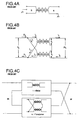
- a 9:4 impedance matching transformer is assembled from a 1:1 balun as shown in Figure 4A and a 4:1 transformer as shown in Figure 4B .
- these designs result in significant broadband voltage imbalance. This presents problems when designing circuits having uniform or flat frequency response characteristics.
- the potential difference or imbalance across the individual transformer connections of the prior art 9:4 impedance matching transformer shown in Figure 5 is approximately 0.5 to 1.0dB.
- the voltage imbalance reduces the amount of even harmonic cancellation and reduces the overall amplifier gain.
- a typical push-pull design would have an output transformer with a center tap carrying equal direct currents through each half of the primary winding. Therefore, it is necessary to maintain a high degree of symmetry between the separate halves of the primary winding or the transformer becomes the limiting factor in the circuit.
- the balanced to unbalanced broadband transmission line transformer of the present invention improves frequency response across a wide operational bandwidth.
- the present invention significantly improves low frequency output balance by adding an additional transformer winding.
- the additional winding improves the low frequency response to less than 0.2dB across a given design bandwidth.
- Figure 1 is an electrical schematic of a prior art transmission line transformer.
- Figure 2 is an electrical schematic of a prior art impedance matching transmission line transformer.
- Figure 3 is an electrical schematic of a prior art impedance matching transmission line transformer.
- Figure 4A is an electrical schematic of a prior art 1:1 balun.
- Figure 4B is an electrical schematic of a prior art 4:1 transformer.
- Figure 4C is an electrical schematic of a prior art 9:4 transformer.
- Figure 5 is an electrical schematic of a prior art 9:4 unbalanced to unbalanced transformer showing the potential differences across the individual transformer windings.
- Figure 6 is an electrical schematic of a prior art 9:4 balanced to unbalanced transformer showing the potential differences across the individual transformer windings.
- Figure 7 is an electrical schematic of the preferred embodiment.
- Figure 8 is a perspective view of the preferred embodiment shown on a symmetrical magnetic core.
- Figure 9 is an electrical schematic of an alternative embodiment.
- Figure 10 is an electrical schematic of another alternative embodiment.
- the transformer 17 is inserted between a balanced circuit 19 with a characteristic impedance of (9/4)R L Ohms and an unbalanced circuit 21 with a load impedance of R L Ohms.
- the transformer 17 comprises three 1:1 transmission line transformers, TL-A 23 , TL-B 25 and TL-C 27 with TL-C 27 having three separate windings. Winding g 1 -g 29 of transformer TL-C 27 performs the current balancing function.
- Transformers TL-A 23 , TL-B 25 and TL-C 27 can share a symmetrical magnetic coupling 43 or be constructed with individual cores.
- the three transformers TL-A 23 , TL-B 25 and TL-C 27 are shown in Figure 7 along with the requisite interconnections as a 9:4 impedance transformation between the balanced 19 and unbalanced 21 circuits.
- Node 1 45 and node 2 47 are the balanced plus and minus signal conductors.
- Node 3 49 is the unbalanced signal conductor.
- Node 4 51 is at ground potential.
- Node 5 53 and node 6 55 are common winding connections.
- Node 1 45 is an external connection for transformer TL-A 23 winding a 1 and transformer TL-B 25 winding c 1 .
- Node 2 47 is an external connection for transformer TL-C 27 winding f 1 .
- Node 3 49 is an external connection for transformer TL-A 23 winding a and transformer TL-C 27 winding e.
- Node 4 51 is an external connection for transformer TL-B 25 winding d and transformer TL-C winding f.
- Node 5 53 is a common connection for transformer TL-A 23 winding b 1 , transformer TL-B 25 winding d 1 and transformer TL-C 27 winding e 1 .
- Node 6 55 is a common connection for transformer TL-A 23 winding b and transformer TL-B 25 winding c.
- each transformer determines the inductance and capacitance of the transformer mutual coupling and also determines the frequency response.
- This common mode inductance determines the low frequency response of the transformer. Frequencies above the low frequency limit are coupled through the transformer and are unaffected by the common mode inductance.
- the high frequency limit is determined by each transformer winding length and parasitic capacitance introduced by the common mode inductance and wire interconnections.
- the inductance of each winding must have high impedance so that the signal does not bypass the transmission line.
- the maximum transformer winding length is ⁇ /4 where ⁇ is the wavelength at the highest expected frequency.
- the low frequency output response is improved by adding the balance winding g 1 -g 29 to transformer TL-C 27.
- the construction of each transformer, TL-A 23 , TL-B 25 and TL-C 27 have all windings wound in the same direction so that magnetic field cancellation does not result.
- the balance winding g 1 -g 29 must be connected between node 1 45 and node 4 51 , ground. From either balanced signal carrying conductor of the balanced circuit 19 exists two separate ground paths from node 1 45 or node 2 47 to ground.
- the voltages across each node of the prior art design are as follows: Transmission Line Nodes 1 ( 63 ) to 3 ( 67 ) -0.5V 1 Transformer A ( 57 ) Nodes 5 ( 71 ) to 6 ( 73 ) Transmission Line Nodes 1 ( 63 ) to 6 ( 73 ) +0.5V 1 Transformer B ( 59 ) Nodes 5 ( 71 ) to 4 ( 69 ) Transmission Line Nodes 5 ( 71 ) to 3 ( 67 ) -1.5V 1 Transformer C ( 61 ) Nodes 2 ( 65 ) to 4 ( 69 )
- the balance winding 29 of transformer 17 between node 1 45 and node 4 51 results in a potential difference of 1.5V 1 . Adding the balance winding 29 balances the voltage across the load. The balance winding 29 also decreases the transformer 17 imbalance to less than 0.2dB across a given operational bandwidth.
Landscapes
- Coils Or Transformers For Communication (AREA)
- Cable Transmission Systems, Equalization Of Radio And Reduction Of Echo (AREA)
Applications Claiming Priority (2)
| Application Number | Priority Date | Filing Date | Title |
|---|---|---|---|
| US789372 | 1997-01-24 | ||
| US08/789,372 US5767754A (en) | 1997-01-24 | 1997-01-24 | Balanced to unbalanced transmission line impedance transformer exhibiting low insertion loss |
Publications (3)
| Publication Number | Publication Date |
|---|---|
| EP0855794A2 true EP0855794A2 (de) | 1998-07-29 |
| EP0855794A3 EP0855794A3 (de) | 1999-12-15 |
| EP0855794B1 EP0855794B1 (de) | 2003-05-14 |
Family
ID=25147448
Family Applications (1)
| Application Number | Title | Priority Date | Filing Date |
|---|---|---|---|
| EP98300411A Expired - Lifetime EP0855794B1 (de) | 1997-01-24 | 1998-01-21 | Breitbandimpedanzanpassungstransformator |
Country Status (3)
| Country | Link |
|---|---|
| US (1) | US5767754A (de) |
| EP (1) | EP0855794B1 (de) |
| DE (1) | DE69814484T2 (de) |
Cited By (1)
| Publication number | Priority date | Publication date | Assignee | Title |
|---|---|---|---|---|
| US11309668B2 (en) | 2019-08-30 | 2022-04-19 | Rohde & Schwarz Gmbh & Co. Kg | Wideband coupler |
Families Citing this family (19)
| Publication number | Priority date | Publication date | Assignee | Title |
|---|---|---|---|---|
| JPH10116732A (ja) * | 1996-10-09 | 1998-05-06 | Nec Corp | 伝送線路トランス及びこれを使用した増幅ユニット |
| US6337608B1 (en) * | 1998-09-22 | 2002-01-08 | Tdk Rf Solutions, Inc. | Formation of a transmission-line transformer providing a frequency-dependent impedance transformation ratio |
| US6381166B1 (en) * | 1998-09-28 | 2002-04-30 | Texas Instruments Incorporated | Semiconductor memory device having variable pitch array |
| US6130588A (en) * | 1998-11-12 | 2000-10-10 | Raytheon Company | Dual line power transformer |
| US6411173B1 (en) * | 1998-12-08 | 2002-06-25 | Honeywell International Inc. | Method to achieve a DC balanced signal databus interface using combination of ethernet and RS-485 protocols with step-up transformer coupling |
| EP1080530B1 (de) * | 1999-03-23 | 2009-09-16 | Nxp B.V. | Anordnung mit einem impedanzwandler und einem symmetrierübertrager |
| US6239668B1 (en) * | 1999-04-14 | 2001-05-29 | General Instrument Corporation | RF balun and transformer with shunt compensation transmission line |
| JP2003059905A (ja) * | 2001-07-31 | 2003-02-28 | Applied Materials Inc | エッチング方法、キャパシタの製造方法、および半導体装置 |
| US6844803B2 (en) * | 2002-02-15 | 2005-01-18 | Mci, Inc. | Thirty-degree length impedance transformer |
| WO2003071677A1 (de) * | 2002-02-25 | 2003-08-28 | Infineon Technologies Ag | Filterschaltung |
| US6819200B2 (en) * | 2002-07-26 | 2004-11-16 | Freescale Semiconductor, Inc. | Broadband balun and impedance transformer for push-pull amplifiers |
| US7319435B2 (en) * | 2003-09-08 | 2008-01-15 | Pdseelectronics, Inc. | Balun for an antenna |
| US7583160B2 (en) * | 2004-09-17 | 2009-09-01 | Bae Systems Advanced Technologies, Inc. | Broadband transmission line transformer |
| US7683735B2 (en) * | 2005-02-16 | 2010-03-23 | Murata Manufacturing Co., Ltd. | Balanced acoustic wave filter |
| US7724484B2 (en) * | 2006-12-29 | 2010-05-25 | Cobham Defense Electronic Systems Corporation | Ultra broadband 10-W CW integrated limiter |
| GB2456522B (en) * | 2008-01-16 | 2012-08-01 | Technetix Group Ltd | Signal splitter |
| DE102011078549B4 (de) | 2011-07-01 | 2014-10-23 | Siemens Aktiengesellschaft | Breitbandiger Balun |
| GB201209086D0 (en) * | 2012-05-24 | 2012-07-04 | Technetix Bv | Improvements relating to Ferromagnetic Transformer Cores |
| US9071229B1 (en) * | 2013-07-30 | 2015-06-30 | Scientific Components Corporation | Miniature multi-decade GHz balun |
Citations (4)
| Publication number | Priority date | Publication date | Assignee | Title |
|---|---|---|---|---|
| DE857648C (de) * | 1943-10-20 | 1952-12-01 | Patelhold Patentverwertung | Spulenaehnliches Leitungsgebilde mit stetig verteilten Leitungskonstanten |
| DE1121668B (de) * | 1960-10-28 | 1962-01-11 | Telefunken Patent | Anordnung zur Verbindung einer erdunsymmertrischen mit einer erdsymmetrischen Hochfrequenzanordnung |
| US3114120A (en) * | 1959-07-09 | 1963-12-10 | Westinghouse Electric Corp | Radio frequency voltage balancing device |
| DE1271230B (de) * | 1966-01-13 | 1968-06-27 | Telefunken Patent | Hochfrequenz-Symmetriertransformator |
Family Cites Families (8)
| Publication number | Priority date | Publication date | Assignee | Title |
|---|---|---|---|---|
| US3882432A (en) * | 1974-06-28 | 1975-05-06 | Us Army | RF broadband transmission line impedance matching transformer pair for less than 4 to 1 impedance transformations |
| JPS5459859A (en) * | 1977-10-20 | 1979-05-14 | Sanyo Electric Co Ltd | Input transformer device of television picture receiver |
| US4717896A (en) * | 1985-03-21 | 1988-01-05 | And Yet, Inc. | Balun |
| JPH0687526B2 (ja) * | 1987-08-19 | 1994-11-02 | 株式会社村田製作所 | 広帯域ミキサ |
| US5361409A (en) * | 1991-03-12 | 1994-11-01 | Watkins Johnson Company | FET mixer having transmission line transformer |
| US5319535A (en) * | 1993-08-19 | 1994-06-07 | Westinghouse Electric Corp. | Active power line conditioner having capability for rejection of common-mode disturbances |
| US5420551A (en) * | 1994-06-29 | 1995-05-30 | At&T Corp. | Circuit for broadband video transmission over unshielded twisted wire pairs |
| US5495212A (en) * | 1994-12-19 | 1996-02-27 | Bh Electronics, Inc. | Coupling device connecting an unbalanced signal line to a balanced signal line |
-
1997
- 1997-01-24 US US08/789,372 patent/US5767754A/en not_active Expired - Lifetime
-
1998
- 1998-01-21 DE DE69814484T patent/DE69814484T2/de not_active Expired - Fee Related
- 1998-01-21 EP EP98300411A patent/EP0855794B1/de not_active Expired - Lifetime
Patent Citations (4)
| Publication number | Priority date | Publication date | Assignee | Title |
|---|---|---|---|---|
| DE857648C (de) * | 1943-10-20 | 1952-12-01 | Patelhold Patentverwertung | Spulenaehnliches Leitungsgebilde mit stetig verteilten Leitungskonstanten |
| US3114120A (en) * | 1959-07-09 | 1963-12-10 | Westinghouse Electric Corp | Radio frequency voltage balancing device |
| DE1121668B (de) * | 1960-10-28 | 1962-01-11 | Telefunken Patent | Anordnung zur Verbindung einer erdunsymmertrischen mit einer erdsymmetrischen Hochfrequenzanordnung |
| DE1271230B (de) * | 1966-01-13 | 1968-06-27 | Telefunken Patent | Hochfrequenz-Symmetriertransformator |
Non-Patent Citations (1)
| Title |
|---|
| GRANBERG H O: "COMBINE POWER WITHOUT COMPROMISING PERFORMANCE" ELECTRONIC DESIGN, vol. 28, no. 15, 19 July 1980 (1980-07-19), pages 181-187, XP002047129 ISSN: 0013-4872 * |
Cited By (1)
| Publication number | Priority date | Publication date | Assignee | Title |
|---|---|---|---|---|
| US11309668B2 (en) | 2019-08-30 | 2022-04-19 | Rohde & Schwarz Gmbh & Co. Kg | Wideband coupler |
Also Published As
| Publication number | Publication date |
|---|---|
| DE69814484D1 (de) | 2003-06-18 |
| EP0855794A3 (de) | 1999-12-15 |
| DE69814484T2 (de) | 2004-04-01 |
| EP0855794B1 (de) | 2003-05-14 |
| US5767754A (en) | 1998-06-16 |
Similar Documents
| Publication | Publication Date | Title |
|---|---|---|
| EP0855794B1 (de) | Breitbandimpedanzanpassungstransformator | |
| US6407648B1 (en) | Four-way non-directional power combiner | |
| US10447230B2 (en) | Transformer of the balanced-unbalanced type | |
| US7839232B2 (en) | Broadband transmission line transformer | |
| US5986617A (en) | Multiband antenna matching unit | |
| US6750752B2 (en) | High power wideband balun and power combiner/divider incorporating such a balun | |
| US6472950B1 (en) | Broadband coupled-line power combiner/divider | |
| CA2366582C (en) | Rf transformer with compensation transmission line | |
| US20070075802A1 (en) | Wide-bandwidth balanced transformer | |
| US4839616A (en) | Broadband impedance transformer | |
| KR19990044630A (ko) | 고임피던스 비 광대역 트랜스포머 회로 | |
| US4121180A (en) | Broadband directional coupler | |
| US6545564B1 (en) | RF signal divider | |
| US6121853A (en) | Broadband coupled-line power combiner/divider | |
| JPH01305604A (ja) | インピーダンス変換装置 | |
| US5130678A (en) | Transmission line transformer with DC isolation | |
| US5929738A (en) | Triple core toroidal transformer | |
| US6756874B2 (en) | Series transmission line transformer | |
| US4916415A (en) | Balanced, impedance matched, coupling device | |
| JPS643335B2 (de) | ||
| US4295107A (en) | Impedance transformation network | |
| US6572287B1 (en) | Assembly of an impedance transformer and a balun transformer | |
| JP3169657B2 (ja) | 結合度を任意に設定し得る方向性分岐器 | |
| CN201097459Y (zh) | 一种宽带射频分配器 | |
| JPS6115629Y2 (de) |
Legal Events
| Date | Code | Title | Description |
|---|---|---|---|
| PUAI | Public reference made under article 153(3) epc to a published international application that has entered the european phase |
Free format text: ORIGINAL CODE: 0009012 |
|
| AK | Designated contracting states |
Kind code of ref document: A2 Designated state(s): DE FR GB |
|
| AX | Request for extension of the european patent |
Free format text: AL;LT;LV;MK;RO;SI |
|
| PUAL | Search report despatched |
Free format text: ORIGINAL CODE: 0009013 |
|
| AK | Designated contracting states |
Kind code of ref document: A3 Designated state(s): AT BE CH DE DK ES FI FR GB GR IE IT LI LU MC NL PT SE |
|
| AX | Request for extension of the european patent |
Free format text: AL;LT;LV;MK;RO;SI |
|
| 17P | Request for examination filed |
Effective date: 20000422 |
|
| AKX | Designation fees paid |
Free format text: AT BE CH LI |
|
| RBV | Designated contracting states (corrected) |
Designated state(s): DE FR GB |
|
| REG | Reference to a national code |
Ref country code: DE Ref legal event code: 8566 |
|
| 17Q | First examination report despatched |
Effective date: 20010928 |
|
| GRAG | Despatch of communication of intention to grant |
Free format text: ORIGINAL CODE: EPIDOS AGRA |
|
| GRAG | Despatch of communication of intention to grant |
Free format text: ORIGINAL CODE: EPIDOS AGRA |
|
| GRAG | Despatch of communication of intention to grant |
Free format text: ORIGINAL CODE: EPIDOS AGRA |
|
| GRAH | Despatch of communication of intention to grant a patent |
Free format text: ORIGINAL CODE: EPIDOS IGRA |
|
| GRAH | Despatch of communication of intention to grant a patent |
Free format text: ORIGINAL CODE: EPIDOS IGRA |
|
| GRAA | (expected) grant |
Free format text: ORIGINAL CODE: 0009210 |
|
| STAA | Information on the status of an ep patent application or granted ep patent |
Free format text: STATUS: THE PATENT HAS BEEN GRANTED |
|
| AK | Designated contracting states |
Designated state(s): DE FR GB |
|
| REG | Reference to a national code |
Ref country code: GB Ref legal event code: FG4D |
|
| REF | Corresponds to: |
Ref document number: 69814484 Country of ref document: DE Date of ref document: 20030618 Kind code of ref document: P |
|
| PLBE | No opposition filed within time limit |
Free format text: ORIGINAL CODE: 0009261 |
|
| ET | Fr: translation filed | ||
| 26N | No opposition filed |
Effective date: 20040217 |
|
| PGFP | Annual fee paid to national office [announced via postgrant information from national office to epo] |
Ref country code: GB Payment date: 20051209 Year of fee payment: 9 |
|
| PGFP | Annual fee paid to national office [announced via postgrant information from national office to epo] |
Ref country code: FR Payment date: 20060104 Year of fee payment: 9 |
|
| PGFP | Annual fee paid to national office [announced via postgrant information from national office to epo] |
Ref country code: DE Payment date: 20060131 Year of fee payment: 9 |
|
| PG25 | Lapsed in a contracting state [announced via postgrant information from national office to epo] |
Ref country code: DE Free format text: LAPSE BECAUSE OF NON-PAYMENT OF DUE FEES Effective date: 20070801 |
|
| GBPC | Gb: european patent ceased through non-payment of renewal fee |
Effective date: 20070121 |
|
| REG | Reference to a national code |
Ref country code: FR Ref legal event code: ST Effective date: 20070930 |
|
| PG25 | Lapsed in a contracting state [announced via postgrant information from national office to epo] |
Ref country code: GB Free format text: LAPSE BECAUSE OF NON-PAYMENT OF DUE FEES Effective date: 20070121 |
|
| PG25 | Lapsed in a contracting state [announced via postgrant information from national office to epo] |
Ref country code: FR Free format text: LAPSE BECAUSE OF NON-PAYMENT OF DUE FEES Effective date: 20070131 |