EP0855560A2 - Ventilation device - Google Patents
Ventilation device Download PDFInfo
- Publication number
- EP0855560A2 EP0855560A2 EP97112976A EP97112976A EP0855560A2 EP 0855560 A2 EP0855560 A2 EP 0855560A2 EP 97112976 A EP97112976 A EP 97112976A EP 97112976 A EP97112976 A EP 97112976A EP 0855560 A2 EP0855560 A2 EP 0855560A2
- Authority
- EP
- European Patent Office
- Prior art keywords
- ventilation
- filter elements
- housing
- filter element
- ventilation device
- Prior art date
- Legal status (The legal status is an assumption and is not a legal conclusion. Google has not performed a legal analysis and makes no representation as to the accuracy of the status listed.)
- Granted
Links
Images


Classifications
-
- F—MECHANICAL ENGINEERING; LIGHTING; HEATING; WEAPONS; BLASTING
- F24—HEATING; RANGES; VENTILATING
- F24F—AIR-CONDITIONING; AIR-HUMIDIFICATION; VENTILATION; USE OF AIR CURRENTS FOR SCREENING
- F24F13/00—Details common to, or for air-conditioning, air-humidification, ventilation or use of air currents for screening
- F24F13/28—Arrangement or mounting of filters
-
- F—MECHANICAL ENGINEERING; LIGHTING; HEATING; WEAPONS; BLASTING
- F24—HEATING; RANGES; VENTILATING
- F24F—AIR-CONDITIONING; AIR-HUMIDIFICATION; VENTILATION; USE OF AIR CURRENTS FOR SCREENING
- F24F8/00—Treatment, e.g. purification, of air supplied to human living or working spaces otherwise than by heating, cooling, humidifying or drying
- F24F8/10—Treatment, e.g. purification, of air supplied to human living or working spaces otherwise than by heating, cooling, humidifying or drying by separation, e.g. by filtering
- F24F8/108—Treatment, e.g. purification, of air supplied to human living or working spaces otherwise than by heating, cooling, humidifying or drying by separation, e.g. by filtering using dry filter elements
-
- F—MECHANICAL ENGINEERING; LIGHTING; HEATING; WEAPONS; BLASTING
- F24—HEATING; RANGES; VENTILATING
- F24F—AIR-CONDITIONING; AIR-HUMIDIFICATION; VENTILATION; USE OF AIR CURRENTS FOR SCREENING
- F24F12/00—Use of energy recovery systems in air conditioning, ventilation or screening
- F24F12/001—Use of energy recovery systems in air conditioning, ventilation or screening with heat-exchange between supplied and exhausted air
- F24F12/006—Use of energy recovery systems in air conditioning, ventilation or screening with heat-exchange between supplied and exhausted air using an air-to-air heat exchanger
-
- F—MECHANICAL ENGINEERING; LIGHTING; HEATING; WEAPONS; BLASTING
- F24—HEATING; RANGES; VENTILATING
- F24F—AIR-CONDITIONING; AIR-HUMIDIFICATION; VENTILATION; USE OF AIR CURRENTS FOR SCREENING
- F24F8/00—Treatment, e.g. purification, of air supplied to human living or working spaces otherwise than by heating, cooling, humidifying or drying
- F24F8/10—Treatment, e.g. purification, of air supplied to human living or working spaces otherwise than by heating, cooling, humidifying or drying by separation, e.g. by filtering
-
- F—MECHANICAL ENGINEERING; LIGHTING; HEATING; WEAPONS; BLASTING
- F24—HEATING; RANGES; VENTILATING
- F24F—AIR-CONDITIONING; AIR-HUMIDIFICATION; VENTILATION; USE OF AIR CURRENTS FOR SCREENING
- F24F12/00—Use of energy recovery systems in air conditioning, ventilation or screening
- F24F12/001—Use of energy recovery systems in air conditioning, ventilation or screening with heat-exchange between supplied and exhausted air
- F24F2012/007—Use of energy recovery systems in air conditioning, ventilation or screening with heat-exchange between supplied and exhausted air using a by-pass for bypassing the heat-exchanger
-
- Y—GENERAL TAGGING OF NEW TECHNOLOGICAL DEVELOPMENTS; GENERAL TAGGING OF CROSS-SECTIONAL TECHNOLOGIES SPANNING OVER SEVERAL SECTIONS OF THE IPC; TECHNICAL SUBJECTS COVERED BY FORMER USPC CROSS-REFERENCE ART COLLECTIONS [XRACs] AND DIGESTS
- Y02—TECHNOLOGIES OR APPLICATIONS FOR MITIGATION OR ADAPTATION AGAINST CLIMATE CHANGE
- Y02B—CLIMATE CHANGE MITIGATION TECHNOLOGIES RELATED TO BUILDINGS, e.g. HOUSING, HOUSE APPLIANCES OR RELATED END-USER APPLICATIONS
- Y02B30/00—Energy efficient heating, ventilation or air conditioning [HVAC]
- Y02B30/56—Heat recovery units
Definitions
- the invention relates to a ventilation device for simultaneous ventilation of rooms and / or for short-circuit operation for air circulation in rooms, especially with a device for heat recovery from the ventilation media flow, with a housing, which is arranged on or in a building wall, for example on the inside of the room, and can be connected to a ventilation duct leading to the outside air for the ventilation and ventilation media flow, wherein two separate flow paths are formed within the housing, and filter elements are provided in both flow paths.
- Ventilation devices of this type are already known made by DE 38 28 011 C2.
- This ventilation device has a plate-shaped Filter element on, which between the exhaust air opening, the Front wall and the passage in the wall of the air duct structure is provided.
- the filter element consists of a flexible Filter material, for example a filter fleece, which is made in one piece.
- a front wall closing the housing is removed and the filter element along - partially arcuate curved - front edges of attached to the housing Cross bars inserted into a chamber.
- Filter element includes a forced ventilation fan U-shaped.
- part of the filter element has no filter function since it is neither in the ventilation nor is in the ventilation media flow of the ventilation device and that the filter element also contrary to its intended Flow direction can be installed if the used filter material in a designated direction having. Installation or maintenance of the ventilation device is due to the arrangement of the filter element complicates that the flexible filter element in the area cannot be seen behind the forced ventilation device can, so that unwanted folds or the like arise can.
- vent and Ventilation media flow different filter elements too use.
- the invention is based on the object, a To provide ventilation device of the type mentioned in the introduction, in which the filter element or elements as possible is or are designed to be easy to maintain. At the same time the optimal function of the filter element can be guaranteed.
- a preferred embodiment provides that the through the filter elements formed an L-shaped assembly Has cross section, through a filter element formed legs at least almost perpendicular to each other stand.
- Filter element with the larger thickness dimension on its Narrow side assigned to a broad side of the filter element which has the smaller thickness dimension is provided.
- the sensible and energy-saving operation of the Ventilation device is guaranteed when to separate the Media flows the area connection between the two Filter elements are sealed and thereby short circuits the Media flows can be prevented.
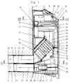
- Fig. 1 of the drawing shows a vertical section through a Ventilation device 1 for simultaneous ventilation of a room 2.
- This ventilation device 1 can be preferably inside the room, on or in a building wall 3 fasten, which has an opening 4 to the outside, in which can be used a tubular ventilation duct 5.
- the tubular ventilation duct 5 has a partition 6, the two longitudinal flow channels 7 and 8 of about same cross-section. Prefers the ventilation duct 5 has a round cross section in which through the partition 6 the two flow channels 7 and 8 are each provided with a semicircular cross section.
- the housing 9 of the ventilation device 1 has a trough-like base body 10 to a pipe section 11 firm, but preferably limited angular movement, is flanged, which is inserted into the opening 4 can be.
- the pipe section 11 tapers at least conical near its free end 12 on its outer circumference, while a diametrical partition 13 of the same in one conically opening groove 14 ends.
- a ventilation media flow path formed in this way 15 ends in a chamber 16 of the housing 9, which is provided with a larger flow cross-section, than the ventilation media flow path 15 itself Chamber 16 through a partition 17 in the aeration media flow path 15 and a vent media flow path 18 divided. The latter is through the pipe section 11 and the ventilation duct 5 in the opening 4 of the building wall 3 Outside air.
- the chamber 16 becomes the inside of the room limited by a front panel 19, which is essentially transverse to the central axis 5a of the ventilation duct 5 or Pipe section 11 extends.
- the front panel 19 is - like all other side walls of chamber 16 - with sound absorbing Material 20 lined.
- the front panel 19 does not consist of a levels, e.g. convex or concave curved, solid plate consists. In the embodiment, it has one - from the inside viewed from chamber 16 - curved outwards, that is concave shape. This means that any existing natural frequencies reduced and the noise reduction inside the chamber 16 favored.
- the partition 17 to the department of the ventilation media flow path 15 from Vent media flow path 18 in substantial parts of a device for heat recovery 25 is formed.
- a device for heat recovery 25 is preferably a recuperative Heat exchanger that has a cross-flow design. He consists of at least one stack of plates or plates 24, which consists of a larger number of individual lamellas or -Plates 23 is composed. Each of them can do one have approximately C-shaped cross section and, as in the 1, 4, 5 and 9 shows the embodiment shown, have an approximately square plan.
- the single lamella or -Plates 23 are formed as thin-walled as possible and are made of a good heat-conducting material, for example aluminum or copper.
- the individual lamellas or -Plates 23 are mutually normal to their plane directional axis rotated 90 ° against each other placed one on top of the other so that flow channels 21 between them and 22 are formed which alternate one around the other 90 ° twisted position so that through them air flows passed through in the layered position successive flow channels 21 and 22, respectively cross.
- the preferred and illustrated embodiment consists of thin-walled profile sections that like already described above, each offset by 90 ° to each other to be ordered. It is possible within the facility for heat recovery 25 or the one forming it Plate stack 24 each parallel to the media flow path 15, 18th running partition walls to provide the surface of the Enlarge device for heat recovery 25 and thus increase their efficiency. Through their directional function can but also the formation of a laminar flow favor.
- the heat recovery device 25 is in the aeration media flow path 15 upstream of a filter element 26, which the air introduced into room 2 from floating Free dirt particles.
- the device is also in the ventilation media flow path 18 Heat recovery 25 upstream a filter element 27, the just like the filter element 26, contamination of the Device for heat recovery 25 from room 2 vacuumed dirt particles prevented.
- the filter elements 26, 27 are both for the ventilation media flow 15 and for the ventilation media stream 18 in the intake path of Forced ventilation devices 28 and 29 respectively. Thereby is achieved that both in the filter elements 26 and 27th as well as in the device for heat recovery 25 a laminar flow is present, the full surface Flow guaranteed. This is supported by the 25 installed in the heat recovery device, (already mentioned) partitions or longitudinal webs, because these for a further alignment of the ventilation and the Ensure ventilation media flow (18).
- the forced ventilation devices 28, 29 are on the upper, horizontal boundary walls 42 and the Forced ventilation devices 29 are on the lower horizontal boundary walls 43 of the chamber 16 are arranged, so that there is the greatest possible distance to the Filter elements 26, 27 and to the device for Heat recovery 25 results. This also results in favorable flow conditions also a longer one Dwell time of the air flow with the associated better heating of the supplied ventilation media stream 15 through the entire housing 9.
- each of the Forced ventilation devices 28, 29 from pairs cooperating fans and that from the in the ventilation media flow 15 arranged fan pair 30, 31 and in Ventilation media stream 18 arranged fan pair 32, 33.
- blowers 30, 31 of the Ventilation media stream 15 arranged in the top of the housing 9 so that they have separate blowout channels 60, but one have common suction space 34.
- Vent media flow 18 and below in the housing 9 arranged blowers 32, 33 both a common Intake chamber 35 and a common blow-out duct 36 Blow-out duct 36 is ideally from pipe section 11 educated.
- the forced ventilation devices 28, 29 are each stored directly in a block-like insert body 37, for example made of foam plastic or foam rubber is formed. This will make the inevitable Internal noise of the blowers 30, 31 and 32, 33 to a minimum reduced or insulated because the fan vibrations do not increase the housing 9 are transmitted.
- Double blower or blower pairs 30/31 or 32/33 By designing as Double blower or blower pairs 30/31 or 32/33 is above also achieved that at the same volume flow, the blower 30, 31, 32, 33 can work at a relatively low speed. However, the volume flow generated with this is compared to one usually used twice as large Single blowers much larger.
- the forced ventilation devices 28, 29 can be in the housing 9 drawer-like - without additional fasteners - be stored. This is achieved through the creation of Open compartments 48, 49 inside the housing 9, in which the one-piece Allow forced ventilation devices 28, 29 to slide in.
- the power supply to the forced ventilation devices 28, 29 takes place, as will be described in more detail below, by attached to the rear wall of the housing 9 Contact points 46 with on the forced ventilation devices 28, 29 attached contact springs 47 cooperate. she will implemented wirelessly, so that the Forced ventilation devices 28, 29 effortlessly open Housing 9 can be removed.
- the arrangement of the Contact points 46 is in a manner known per se chosen so that the forced ventilation devices 28, 29 only in are properly supplied with power so that a possible incorrect assembly remains without consequences.
- the device for heat recovery 25 can Maintenance purposes can be removed from the housing 9. For this is first the pivotally mounted on the housing 9 Front plate 19 pivoted about a lower horizontal axis, so that the chamber 16 is open on the inside of the room.
- the Device for heat recovery 25 25 is together with the Filter elements 26 and 27 mounted on a frame 38, the is pivotable about a bearing axis 39.
- the bearing axis 39 is effective as a snap-snap connection, so that the frame 38 can be removed from the housing 9 in total.
- Of the Frame 38 has limits 40 which in the closed state the front panel 19 at corresponding sealing points 41 of the Bump housing 9 and the front panel 19.
- Filter elements 27, 26 can have different designs to have. So is the filter element 26, which in the aeration media flow 15 lies, with a higher degree of separation equipped as the filter element 27 for the ventilation media flow 18th
- the filter elements 26, 27 are detachable on the frame 38 attached, at least the filter element 26 for the Aeration media stream 15 from the device to Heat recovery 25 is spaced. This ensures that the entire filter element 26 is flowed through. At a Arrangement of the same directly on the device for Heat recovery 25 would, however, with their air-impermeable edge sections meet Filter sections entail a high pressure loss.
- the front plate 19 is curved in cross section to the outside executed and on the inside with insulation material 20 busy.
- the Housing 9 consists of a trough-like base body 10 which a frame 45 is releasably attached. All perpendicular to Main plane of the boundary walls of the Base body 10 are closed, so that if necessary Assembly of the ventilation device 1 also at least partially in one - indicated in FIG. 2 with dash-dotted lines - Niche 3a of the building wall 3 can take place.
- the frame 45 and the base body 10 are provided with seals 10a Flanges 10b connected and with - not shown - Fasteners, e.g. Screws, fastened together.
- the frame 45 When attaching the ventilation device 1 accordingly 2, the frame 45 is detached from the base body 10. Of the Base body 10 is fastened in the wall recess 3a and only then the frame 45 is flush with the wall surface Building wall 3 created. The frame 45 can then on Base body 10 are attached.
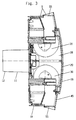
- Fig. 4 shows that provided within the housing 9 Course of the ventilation media flow path 15 using a Basic form of the ventilation device 1.
- the Aeration media stream 15 comes from - in this Representation not visible - flow channel 8 in breakthrough 4 of the building wall 3 by the also not shown Pipe section 11 and enters the chamber 16. From there it follows one with a multitude of redirections hatched arrows 15a marked path.
- Of the Aeration media stream 15 is initially in the chamber 16 from the ventilation media flow 18 through the partition 17 separated, after which it moves upwards through the Filter element 26 and the device for heat recovery 25 leads. From there it continues upwards to Suction side of the on the upper horizontal boundary wall 42nd the ventilation device 27 arranged in the chamber 16. In it, the two fans 30 and 31 Volume flow divided in half.
- a first half of the Volume flow is deflected to the left as shown and directed into a downward chute 50.
- the second half of the volumetric flow is added to this mirror-symmetric direction directed to the right, but what is not visible in Fig. 4.
- At the bottom of each shaft 50 are lateral outlet openings 51 through which the ventilation media flow 15 then gets into the interior of the room.
- the one on each side of the housing 9 and the outside of the chamber 16th along shaft 50 is with sound absorbing Material 20 lined with a liner to the Outer walls 52 to avoid the transfer of Structure-borne noise is generally sufficient.
- the shaft 50 is through Removing the frame 45 accessible from the base body 10.
- a second chamber 54 is formed approximately in the center of the housing 9.
- the Ventilation device 1 necessary electrical components as well the control and display instruments are also arranged, which are not shown.
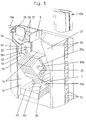
- Fig. 5 is provided within the housing 9
- Course of the ventilation media stream 18 also in one Principle of spatial form recognizable. He leads over Air inlet openings 55 at the top into the interior of the housing 9, as the open arrows 18a make clear.
- With two following right-angled bends 56, 57 he goes in a vertical shaft 58, which is behind the shaft 50 is arranged, so also along the outside of the chamber 16 guided.
- the shaft 58 cut in this illustration opens at the perpendicular boundary walls 59 through - not visible here - openings in the chamber 16 a.
- the filter element 27 to protect the in the vent media flow path 18 subsequently arranged device for Heat recovery 25 is from the rear wall of the housing 9 flows through to the front panel 19, the Ventilation media stream 18 in the suction chamber 35 below the Partition 17 arrives.
- the vent media flow path 18 leads from this - through the forced ventilation device 29 driven - in the flow channel 7 the Ventilation device 1 connects to the outside air.
- Fig. 5 shows by the arrows 18a that the Venting media stream 18 in several places - mostly right-angled - kinked.
- the Forced ventilation device 29 is arranged so that the Blow-out duct 36 of both fans 32 and 33 parallel to Central axis 5a of the ventilation duct 5, which is not visible here runs.
- FIGS. 4 and 5 show each only half of the aeration media flow 15 and the venting media stream 18, the second of which Half mirrored to the vertical central plane of the Ventilation unit 1 is guided.
- the forced ventilation devices 28, 29 both in the ventilation media flow 15 as well as in the venting media stream 18 Have an arrangement in which the suction path of the same - within of the housing 9 of the ventilation device 1 - each longer is dimensioned as the blow-out path. With this arrangement achieved that the operation of the Forced ventilation devices 28, 29 arise Internal noise of the blowers 30, 31 and 32, 33 a maximum Experience damping.
- the base body 10 and the frame 45 of the housing 9 are as Plastic injection molded parts, which is a dimensionally accurate and inexpensive production results.
- De-molding of the base body 10 is the wall 61 of the Shaft 58 or shaft 50 are designed loosely, i.e. the Wall 61 is only on the assembly of the frame 45 on the Base body 10 used. This also enables a Cleaning of those located in the venting media flow path 18 Flow channels that are not directly accessible.
- a preferred embodiment provides that the wall 61 a perfect fit, with soundproofing material on all sides enclosed and provided with a crease 62 Cardboard section exists. This can be in the event of any maintenance of the device simply removed from it and through a new section to be replaced.
- the Forced ventilation device 28 consists of an upper one and a lower housing half 65, 66.
- the - not shown - blower motors are on the bottom 68 of the upper housing half 65 attached.
- the blowers 32 and 33 suck in via the opening 66a and blow out to the side, the blow-out directions mirror-symmetrical to Transverse central axis 67 and away from each other.
- a guide 69 runs along the transverse central axis 67 through an open groove 70 in the upper housing half 65 and by a projection 71 on the lower housing half 66 is formed.
- this guide 69 shows a push rod 72 guided longitudinally, which cooperates at one end 73 with the front panel 19, while with the other end 74 on a push button switch 75 meets.
- the fixation of the lower housing half 66 on the upper Housing half 65 is carried out by the upper housing half 65 molded locking hooks 76, as shown in FIG. 8. This In the assembled state, latching hooks 76 engage in recesses 77 and lock a swivel bearing. This is through laterally open longitudinal eyelets 78 of the lower housing half 66 and in this engaging tab of the upper housing half 65 the is not shown here.
- the forced ventilation device 29 is equivalent to this Way equipped. However, it does not have the guide 69 and has the other blowout direction already described.
- Both forced ventilation devices 28 and 29 are like is highlighted several times, by at least one part Covering with soundproofing material to avoid Structure-borne noise transmissions.
- the profile sections 95, 96 are over that of the Profile bars 91, 92, 93 and the side cheeks 90 formed Frame 38 attached in that its side edges in Longitudinal grooves 91b, 92 and 93b of the profile bars 91, 92, 93 sit in. Additionally there are seals 91c, 92c and 93c appropriate.
- the profile bars 91, 92, 93 also have longitudinal grooves 91d, 92d, 93d seated seals 91e, 92e, 93e on the in a familiar way with those already ahead with reference to FIG. 1 sealing points 41 of the shown housing or front panel 19 cooperate.
- the side cheeks 90 are in the illustrated embodiment provided with a bore 97 to which a lateral Opening 98 connects.
- the center of the bore 97 forms a bearing axis 39 around which, as already described, the entire frame 38 is pivotally mounted.
- the bearing axis 39 in the housing 9 can be close to its end Sheathed flattened cylinder rod are formed, the has approximately the diameter 99 of the hole 97. In the field of Flattening corresponds to its cross section approximately the width 98a the opening 98, whereby a kind Bayonet lock arises, via which the frame 38 in the Housing 9 can be fixed immovably.
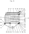
- Fig. 10 shows the frame 38 in the housing 9. Die Filter elements 26, 27, as already described, by the frame 38 worn, which also the device for Heat recovery 25 picks up.
- the filter elements 26, 27 are firmly connected and through an effective adhesive bond between them. This Adhesive connection works across the entire width of the Filter elements 26, 27 and causes the filter elements 26, 27 form a structural unit.
- This unit has an L-shaped cross section thereof Legs are formed by the filter elements 26, 27 that are at least almost perpendicular to each other. This will achieved that the filter elements 26, 27 after pivoting of the frame 38 together in one operation to the frame 38 can be removed.
- the L-shaped cross section of the Unit encompasses the device for Heat recovery 25 on two sides, being through the fixed Connection of the filter elements 26, 27 also a safe and spaced attachment of the filter element 26 relative to the Heat recovery device 25 is ensured.
- the filter element 26 consists of a pleated filter material by a surrounding frame 100 is enclosed.
- frame materials come e.g. Cardboard or metal in question.
- the filter element 27 consists of a filter mat formed by a fleece.
- the frame 100 supports or holds the filter element 26 on the one hand with its peripheral edges 100a, 100b between the longitudinal edges 93f of the profile bar 93. On the other hand, the frame 100 with one protruding beyond the plane of the filter element 26 Edge 100b against the heat recovery device 25 and the rear wall of the base body 10 is supported.
- connection of the filter elements can of course can also be designed to be detachable, the filter element 27 for example by means of an attached Velcro fastener is held on the filter element 26.
- Overlap area 103 makes sense that the filter element 26th with the larger thickness dimensions 101 on its narrow side 104 assigned to a broad side 105 of the filter element 27 which has the smaller thickness dimension 102. This maximizes the overlap area 103 and the Connection is expanded as much as possible. Also will achieved that consisting of the filter elements 26, 27 Unit receives a stable structure, the one has greater dimensional stability than the individual components.
- FIG. 10 in connection with FIG. 9, has the frame 38 in the operating state relative to the housing inclined installation position.
- the one at the top of the filter elements 26 and 27 located corner area 106 is with a chamfer 107 provided in the operating state of the ventilation device 1 runs parallel to the rear wall of the base body 10. Since the filter element 27 via this recessed chamfer 107 protrudes - as Fig. 9 shows - the material of the Filter element 27 in the installed state to the level of recessed chamfer 107 deforms and acts as a seal with the rear wall of the base body 9 together.
- the structural unit with the L-shaped cross section is 10, in the operating state of the Ventilation device 1 inclined so that the angle which of the leg of the L-shaped cross section is enclosed, is halved by the horizontal.
- the filter element 27 Forces equally on both filter elements 26, 27 and Frame 38 transmitted.
- the changing of the filter elements 26, 27 happens - how already described above - by pivoting the Frame 38 around the bearing axis 39 with the front panel 19 open whereby for cleaning purposes or for changing the by the Filter elements 26, 27 formed the entire unit Frame 38 removed from the housing 9 of the ventilation device 1 can be.
- the arrangement of the filter elements 26, 27 as a structural unit also causes an incorrect passage direction of the Media flows are counteracted by this.
- the different thickness dimensions 102, 103 of the Filter elements 26, 27 do not require that the filter elements 26, 27 different degrees of absorption or deposition exhibit.
Abstract
Description
Die Erfindung betrifft eine Lüftungsvorrichtung zum
gleichzeitigen Be- und Entlüften von Räumen und/oder zum
Kurzschlußbetrieb für die Luftumwälzung in Räumen,
insbesondere mit einer Einrichtung zur Wärmerückgewinnung aus
dem Entlüftungs-Medienstrom,
mit einem Gehäuse, das - beispielsweise rauminnenseitig - an
oder in einer Gebäudewand angeordnet sowie an je einen zur
Außenluft führenden Lüftungskanal für den Be- und den
Entlüftungs-Medienstrom anschließbar ist,
wobei innerhalb des Gehäuses zwei voneinander getrennte
Strömungswege ausgebildet sind,
und wobei in beiden Strömungswegen Filterelemente vorgesehen
sind.The invention relates to a ventilation device for simultaneous ventilation of rooms and / or for short-circuit operation for air circulation in rooms,
especially with a device for heat recovery from the ventilation media flow,
with a housing, which is arranged on or in a building wall, for example on the inside of the room, and can be connected to a ventilation duct leading to the outside air for the ventilation and ventilation media flow,
wherein two separate flow paths are formed within the housing,
and filter elements are provided in both flow paths.
Lüftungsvorrichtungen dieser Art sind bereits bekannt geworden durch die DE 38 28 011 C2.Ventilation devices of this type are already known made by DE 38 28 011 C2.
Diese Lüftungsvorrichtung weist ein plattenförmiges Filterelement auf, welches zwischen der Abluftöffnung, der Frontwand und dem Durchlaß in der Wand des Luftführungs-Baukörpers vorgesehen ist. This ventilation device has a plate-shaped Filter element on, which between the exhaust air opening, the Front wall and the passage in the wall of the air duct structure is provided.
Des Filterelement besteht aus einem biegsamen Filterwerkstoff, beispielsweise einem Filtervlies, welches einstückig hergestellt ist. Zur Montage des Filterelementes wird eine das Gehäuse verschließende Frontwand abgenommen und das Filterelement entlang von - teilweise bogenförmig gekrümmten - Stirnkanten von am Gehäuse befestigten Querstegen in eine Kammer eingeschoben.The filter element consists of a flexible Filter material, for example a filter fleece, which is made in one piece. For mounting the filter element a front wall closing the housing is removed and the filter element along - partially arcuate curved - front edges of attached to the housing Cross bars inserted into a chamber.
Ein sich daran anschließender, nach außen freiliegender Längenabschnitt des Filterelementes wird parallel zur Frontplatte senkrecht nach oben geführt, so daß das Filterelement ein Zwangslüftungsgebläse U-förmig umfaßt.A subsequent one, exposed to the outside Length section of the filter element is parallel to Front plate led vertically upwards, so that Filter element includes a forced ventilation fan U-shaped.
Es ist dabei von Nachteil, daß ein Teil des Filterelementes keine Filterfunktion aufweist, da es weder im Belüftungsnoch im Entlüftungs-Medienstrom der Lüftungsvorrichtung liegt und daß das Filterelement auch entgegen seiner vorgesehenen Durchströmungsrichtung eingebaut werden kann, wenn der verwendete Filterwerkstoff eine dafür vorgesehene Richtung aufweist. Die Montage bzw. Wartung der Lüftungsvorrichtung ist durch die Anordnung des Filterelementes dahingehend erschwert, daß das biegsame Filterelement in dem Bereich hinter der Zwangslüftungsvorrichtung nicht eingesehen werden kann, so daß nicht gewünschte Falten od. dgl. entstehen können.It is disadvantageous that part of the filter element has no filter function since it is neither in the ventilation nor is in the ventilation media flow of the ventilation device and that the filter element also contrary to its intended Flow direction can be installed if the used filter material in a designated direction having. Installation or maintenance of the ventilation device is due to the arrangement of the filter element complicates that the flexible filter element in the area cannot be seen behind the forced ventilation device can, so that unwanted folds or the like arise can.
Auch ist es nicht möglich, für den Entlüftungs- und Belüftungs-Medienstrom unterschiedliche Filterelemente zu verwenden.Nor is it possible for the vent and Ventilation media flow different filter elements too use.
Der Erfindung liegt nun die Aufgabe zugrunde, eine Lüftungsvorrichtung der eingangs erwähnten Art zu schaffen, bei der das oder die Filterelemente möglichst montage- und wartungsfreundlich ausgelegt ist bzw. sind. Gleichzeitig soll die optimale Funktion des Filterelements gewährleistet sein. The invention is based on the object, a To provide ventilation device of the type mentioned in the introduction, in which the filter element or elements as possible is or are designed to be easy to maintain. At the same time the optimal function of the filter element can be guaranteed.
Die Lösung dieses Problems wird erfindungsgemäß nach dem
Kennzeichen des Anspruchs 1 dadurch erreicht, daß die
Filterelemente miteinander eine Baueinheit bilden, die von
einem Rahmen od. dgl. getragen ist, der ggf. auch die
Einrichtung zur Wärmerückgewinnung trägt.The solution to this problem is according to the invention
Characteristic of
Dadurch wird erreicht, daß die Filterelemente gemeinsam - in einem Arbeitsgang - ein- und ausgebaut werden können. Auch ist eine erhöhte Stabilität der Baueinheit die Folge und Abdichtprobleme der Filterelemente zueinander entfallen.This ensures that the filter elements together - in one operation - can be installed and removed. Also the result is an increased stability of the structural unit and There are no sealing problems between the filter elements.
Eine bevorzugte Ausführungsform sieht vor, daß daß die durch die Filterelemente gebildete Baueinheit einen L-förmigen Querschnitt aufweist, dessen durch ein Filterelement gebildete Schenkel zumindest nahezu senkrecht aufeinander stehen.A preferred embodiment provides that the through the filter elements formed an L-shaped assembly Has cross section, through a filter element formed legs at least almost perpendicular to each other stand.
Für den Fall, daß die Filterelemnte unterschiedliche Dickenabmessungen aufweisen, ist vorgesehen, daß das Filterelement mit der größeren Dickenabmessung an seiner Schmalseite einer Breitseite des Filterelementes zugeordnet ist, welches die geringere Dickenabmessung aufweist.In the event that the filter elements differ Have thickness dimensions, it is provided that Filter element with the larger thickness dimension on its Narrow side assigned to a broad side of the filter element which has the smaller thickness dimension.
Eine kostengünstige Herstellung ist gewährleistet, wenn die Filterelemente mittels einer Klebeverbindung verbunden sind.Inexpensive production is guaranteed if the Filter elements are connected by means of an adhesive connection.
Der sinnvolle und energiesparende Betrieb der Lüftungsvorrichtung ist gewährleistet, wenn zur Trennung der Medienströme die Flächenverbindung zwischen den beiden Filterelementen abgedichtet sind und dadurch Kurzschlüsse der Medienströme verhindert werden.The sensible and energy-saving operation of the Ventilation device is guaranteed when to separate the Media flows the area connection between the two Filter elements are sealed and thereby short circuits the Media flows can be prevented.
Weitere Merkmale und Vorteile des Gegenstandes der Erfindung werden nachfolgend an in den Zeichnungen dargestellten Ausführungsbeispielen erläutert. Hierbei zeigen
- Fig.1
- eine Lüftungsvorrichtung in verkleinertem Vertikalschnitt
- Fig. 2
- einen Horizontalabschnitt durch die Lüftungsvorrichtung nach Fig. 1 entlang der Linie II-II,
- Fig. 3
- einen Horizontalschnitt durch die Lüftungsvorrichtung nach Fig. 1 entlang der Linie III-III,
- Fig. 4
- eine schematisierte Raumform-Darstellung der Lüftungsvorrichtung mit durch schraffierte Pfeile gekennzeichnetem Belüftungs-Medienstromweg,
- Fig. 5
- eine der Fig. 4 entsprechende Darstellung, jedoch mit durch offene Pfeile gekennzeichnetem Entlüftungs-Medienstromweg,
- Fig. 6
- im Vertikalschnitt das Gehäuse einer Zwangslüftungsvorrichtung,
- Fig. 7
- die untere Hälfte des Gehäuses nach Fig. 6 in Draufsicht gemäß Pfeilrichtung VII,
- Fig. 8
- in größerem Maßstab einen Schnitt entlang der Linie VIII-VIII in Fig.7.
- Fig. 9
- im Querschnitt die Einrichtung zur Wärmerückgewinnung in ausführlicher Darstellung und
- Fig. 10
- einen vergrößerten Ausschnitt der Lüftungsvorrichtung nach Fig. 1.
- Fig. 1
- a ventilation device in a reduced vertical section
- Fig. 2
- a horizontal section through the ventilation device of FIG. 1 along the line II-II,
- Fig. 3
- 2 shows a horizontal section through the ventilation device according to FIG. 1 along the line III-III,
- Fig. 4
- 2 shows a schematic representation of the spatial shape of the ventilation device with a ventilation media flow path identified by hatched arrows,
- Fig. 5
- 4 shows a representation corresponding to FIG. 4, but with a venting medium flow path identified by open arrows,
- Fig. 6
- in vertical section the housing of a forced ventilation device,
- Fig. 7
- 6 the top half of the housing according to FIG. 6 in plan view according to arrow direction VII,
- Fig. 8
- on a larger scale a section along the line VIII-VIII in Fig.7.
- Fig. 9
- in cross section the device for heat recovery in a detailed representation and
- Fig. 10
- an enlarged section of the ventilation device of FIG. 1st
Fig. 1 der Zeichnung zeigt einen Vertikalschnitt durch eine
Lüftungsvorrichtung 1 zum gleichzeitigen Be- und Entlüften
eines Raumes 2. Diese Lüftungsvorrichtung 1 läßt sich,
vorzugsweise rauminnenseitig, an oder in einer Gebäudewand 3
befestigen, die einen Durchbruch 4 nach außen aufweist, in
den sich ein rohrförmiger Lüftungskanal 5 einsetzen läßt.Fig. 1 of the drawing shows a vertical section through a
Der rohrförmige Lüftungskanal 5 hat dabei eine Trennwand 6,
die zwei längsverlaufende Strömungskanäle 7 und 8 von etwa
gleichem Querschnitt gegeneinander abgrenzt. Bevorzugt
besitzt der Lüftungskanal 5 einen runden Querschnitt, in dem
durch die Trennwand 6 die beiden Strömungskanäle 7 und 8
jeweils mit halbkreisförmigem Querschnitt vorgesehen sind.The
Das Gehäuse 9 der Lüftungsvorrichtung 1 besitzt einen
wannenartigen Grundkörper 10 an den ein Rohrabschnitt 11
fest, vorzugsweise aber begrenzt winkelbeweglich,
angeflanscht ist, der in den Durchbruch 4 hineingesteckt
werden kann. Der Rohrabschnitt 11 verjüngt sich wenigstens
nahe seinem freien Ende 12 an seinem Außenumfang konisch,
während eine diametrale Trennwand 13 desselben in einer sich
konisch öffnenden Nut 14 endet. Durch diese Ausgestaltung des
Rohrabschnitts 11 wird eine problemlose Kupplung der
Lüftungsvorrichtung 1 mit dem Lüftungskanal 5 erreicht, weil
der Rohrabschnitt 11 mit seinem verjüngten freien Ende 12 in
den etwas größer bemessenen Lüftungskanal 5 eintauchen kann,
während zugleich die Trennwand 6 des Lüftungskanals 5 in die
konisch geformte Nut 14 der Trennwand 13 ragt.The
Ein auf diese Art und Weise gebildeter Belüftungs-Medienstromweg
15 endet in einer Kammer 16 des Gehäuses 9,
die mit einem größeren Durchströmquerschnitt versehen ist,
als der Belüftungs-Medienstromweg 15 selbst. Dabei wird die
Kammer 16 durch eine Trennwand 17 in den Belüftungs-Medienstromweg
15 und einen Entlüftungs-Medienstromweg 18
geteilt. Letzterer ist dabei durch den Rohrabschnitt 11 und
den Lüftungskanal 5 im Durchbruch 4 der Gebäudewand 3 zur
Außenluft geführt. Zur Rauminnenseite wird die Kammer 16
durch eine Frontplatte 19 begrenzt, die sich im wesentlichen
quer zur Mittelachse 5a des Lüftungskanals 5 bzw. des
Rohrabschnitts 11 erstreckt.A ventilation media flow path formed in this
Durch diese Anordnung wird erreicht, daß jenseits der
Gebäudewand 3 auftretende Schallwellen, die durch den
Lüftungskanal 5 bzw. den Rohrabschnitt 11 in den Raum 2
gerichtet sind, zunächst nur bis in die Kammer 16 gelangen
können. Die Querschnittsänderung (Erweiterung) bewirkt dabei
eine erste Dämpfung. Die Frontplatte 19 ist - ebenso wie alle
anderen Seitenwände der Kammer 16 - mit schallabsorbierendem
Material 20 ausgekleidet. Zusätzlich kann vorgesehen werden,
daß auf dem schallabsorbierenden Material 20 der
Kammerinnenseite - nicht dargestellte - schallabsorbierende
und/oder schallreflektierende Metallplatten angebracht sind,
die den eindringenden Lärm dämmen,dämpfen und reflektieren.
Um einen möglichst effektiven Schallabbau zu erreichen, ist
dabei auch vorgesehen, daß die Frontplatte 19 aus einer nicht
ebenen, z.B. konvex oder konkav gekrümmten, massiven Platte
besteht. Beim Ausführungsbeispiel hat sie eine - vom Inneren
der Kammer 16 aus betrachtet - nach auswärts gewölbte, also
konkave Form. Dadurch werden evtl. vorhandene Eigenfrequenzen
gemindert und die Schallreduzierung im Inneren der Kammer 16
begünstigt.This arrangement ensures that beyond the
Beim dargestellten Ausführungsbeispiel wird die Trennwand 17
zur Abteilung des Belüftungs-Medienstromweges 15 vom
Entlüftungs-Medienstromweg 18 in wesentlichen Teilen von
einer Einrichtung zur Wärmerückgewinnung 25 gebildet. Bei
dieser Einrichtung zur Wärmerückgewinnung 25 handelt es sich
vorzugsweise um einen rekuperativ arbeitenden
Wärmeübertrager, der eine Kreuzstrom-Bauart aufweist. Er
besteht aus mindestens einem Lamellen- bzw. Plattenstapel 24,
der aus einer größeren Anzahl von Einzellamellen bzw.
-Platten 23 zusammengesetzt ist. Von diesen kann jede einen
etwa C-förmigen Querschnitt aufweisen und, wie das in den
Fig. 1, 4, 5 und 9 dargestellte Ausführungsbeispiel zeigt,
einen etwa quadratischen Grundriß haben. Die Einzellamellen- bzw.
-Platten 23 sind dabei möglichst dünnwandig ausgebildet
und bestehen aus einem gut wärmeleitenden Werkstoff,
beispielsweise Aluminium oder Kupfer. Die Einzellamellen bzw.
-Platten 23 sind wechselseitig um eine normal zu ihrer Ebene
gerichtete Achse jeweils um 90° gegeneinander verdreht
aufeinandergelegt, so daß zwischen ihnen Durchströmkanäle 21
und 22 gebildet werden, die abwechselnd eine zueinander um
90° verdrehte Lage haben, damit die durch sie
hindurchgeführten Luftströme sich in den in Schichtlage
aufeinanderfolgenden Strömungskanälen 21 und 22 jeweils
kreuzen.In the illustrated embodiment, the
Die bevorzugte und dargestellte Ausführungsform besteht aus
dünnwandigen Profilabschnitten, die wie bereits
vorbeschrieben, jeweils um 90° zueinander drehwinkel-versetzt
angeordnet werden. Es ist möglich, innerhalb der Einrichtung
zur Wärmerückgewinnung 25 bzw. des sie bildenden
Plattenstapels 24 jeweils parallel zum Medienstromweg 15, 18
verlaufende Zwischenwände vorzusehen, die die Oberfläche der
Einrichtung zur Wärmerückgewinnung 25 vergrößern und somit
deren Wirkungsgrad erhöhen. Durch ihre Richtfunktion können
sie aber auch die Ausbildung einer laminaren Strömung
begünstigen.The preferred and illustrated embodiment consists of
thin-walled profile sections that like already
described above, each offset by 90 ° to each other
to be ordered. It is possible within the facility
for
Der Einrichtung zur Wärmerückgewinnung 25 ist im Belüftungs-Medienstromweg
15 ein Filterelement 26 vorgeordnet, welches
die in den Raum 2 eingeführte Luft von schwebenden
Schmutzpartikeln befreit.The
Auch im Entlüftungs-Medienstromweg 18 ist der Einrichtung zur
Wärmerückgewinnung 25 ein Filterelement 27 vorgelagert, das
ebenso wie das Filterelement 26, eine Verschmutzung der
Einrichtung zur Wärmerückgewinnung 25 durch aus dem Raum 2
abgesaugte Schmutzpartikel verhindert. Die Filterelemente 26,
27 sind sowohl für den Belüftungs-Medienstrom 15 als auch für
den Entlüftungs-Medienstrom 18 im Ansaugweg von
Zwangslüftungsvorrichtungen 28 bzw. 29 angeordnet. Dadurch
wird erreicht, daß sowohl in den Filterelementen 26 und 27
als auch in der Einrichtung zur Wärmerückgewinnung 25 eine
laminare Strömung vorliegt, die deren vollflächige
Durchströmung gewährleistet. Unterstützt wird dies durch die
in der Einrichtung zur Wärmerückgewinnung 25 angebrachten,
(bereits erwähnten) Zwischenwände bzw. Längsstege, weil diese
für eine weitere Ausrichtung des Belüftungs- und des
Entlüftungs-Medienstroms (18) sorgen.The device is also in the ventilation
Die Zwangslüftungsvorrichtungen 28, 29 sind an den oberen,
waagerechten Begrenzungswänden 42 und die
Zwangslüftungsvorrichtungen 29 sind an den unteren
waagerechten Begrenzungswänden 43 der Kammer 16 angeordnet,
so daß sich jeweils eine größtmögliche Entfernung zu den
Filterelementen 26, 27 und zu der Einrichtung zur
Wärmerückgewinnung 25 ergibt. Daraus resultiert neben
günstigen Strömungsverhältnissen auch eine längere
Verweilzeit der Luftströmung mit der damit verbundenen
besseren Erwärmung des zugeführten Belüftungs-Medienstroms 15
durch das gesamte Gehäuse 9. Wie insbesondere auch aus Fig. 2
und 3 hervorgeht, besteht jede der
Zwangslüftungsvorrichtungen 28, 29 aus paarweise
zusammenarbeitenden Gebläsen und zwar aus dem im Belüftungs-Medienstrom
15 angeordneten Gebläsepaar 30, 31 und dem im
Entlüftungs-Medienstrom 18 angeordneten Gebläsepaar 32, 33.The forced
Wie die Fig. 2 und 7 zeigen, sind die Gebläse 30, 31 des
Belüftungs-Medienstroms 15 oben im Gehäuse 9 so angeordnet,
daß sie getrennte Ausblaskanäle 60 aufweisen, jedoch einen
gemeinsamen Ansaugraum 34 haben. Demgegenüber besitzen die im
Entlüftungs-Medienstrom 18 und unten im Gehäuse 9
angeordneten Gebläse 32, 33 sowohl einen gemeinsamen
Ansaugraum 35 als auch einen gemeinsamen Ausblaskanal 36. Der
Ausblaskanal 36 ist dabei idealerweise vom Rohrabschnitt 11
gebildet. Die Zwangslüftungsvorrichtungen 28, 29 sind jeweils
unmittelbar in einem blockartigen Einsatzkörper 37 gelagert,
der beispielsweise aus Schaumkunststoff oder Moosgummi
gebildet ist. Dadurch werden die unvermeidlichen
Eigengeräusche der Gebläse 30, 31 bzw. 32, 33 auf ein Minimum
reduziert bzw. gedämmt, weil die Gebläsevibrationen nicht auf
das Gehäuse 9 übertragen werden. Durch die Ausgestaltung als
Doppelgebläse bzw. Gebläsepaare 30/31 bzw. 32/33 wird darüber
hinaus erreicht, daß bei gleichem Volumenstrom die Gebläse
30, 31, 32, 33 mit relativ geringer Drehzahl arbeiten können.
Der hiermit erzeugte Volumenstrom ist jedoch gegenüber einem
üblicherweise einzusetzenden doppelt so groß bemessenen
Einzel-Gebläse ungleich größer.As shown in FIGS. 2 and 7, the
Die Zwangslüftungsvorrichtungen 28, 29 können in dem Gehäuse
9 schubladenartig - ohne zusätzliche Befestigungsmittel -
gelagert werden. Dies wird erreicht durch Schaffung von zur
Rauminnenseite offenen Fächern 48, 49 innerhalb des Gehäuses
9, in die sich die einteilig ausgebildeten
Zwangslüftungsvorrichtungen 28, 29 einschieben lassen.The forced
Die Stromversorgung der Zwangslüftungsvorrichtungen 28, 29
erfolgt, wie im folgenden noch genauer beschrieben wird,
durch an der Rückwand des Gehäuses 9 angebrachte
Kontaktstellen 46 die mit an den Zwangslüftungsvorrichtungen
28, 29 angebrachten Kontaktfedern 47 zusammenwirken. Sie wird
also kabellos verwirklicht, , so daß die
Zwangslüftungsvorrichtungen 28, 29 mühelos dem geöffneten
Gehäuse 9 entnommen werden können. Die Anordnung der
Kontaktstellen 46 ist dabei in ansich bekannter Art und Weise
so gewählt, daß die Zwangslüftungsvorrichtungen 28, 29 nur in
ordnungsgemäßer Einbaulage mit Strom versorgt werden, so daß
eine evtl. mögliche Fehlmontage folgenlos bleibt. The power supply to the forced
Auch die Einrichtung zur Wärmerückgewinnung 25 kann zur
Wartungszwecken aus dem Gehäuse 9 entnommen werden. Hierzu
wird zunächst die schwenkbar am Gehäuse 9 gelagerte
Frontplatte 19 um eine untere waagerechte Achse verschwenkt,
so daß die Kammer 16 raumminnenseitig offen ist. Die
Einrichtung zur Wärmerückgewinnung 25 25 ist zusammen mit den
Filterelementen 26 und 27 auf einem Rahmen 38 montiert, der
um eine Lagerachse 39 schwenkbar ist. Die Lagerachse 39 ist
dabei als Rast-Schnappverbindung wirksam, so daß der Rahmen
38 insgesamt aus dem Gehäuse 9 entnommen werden kann. Der
Rahmen 38 hat Begrenzungen 40 die im geschlossenen Zustand
der Frontplatte 19 an entsprechende Dichtstellen 41 des
Gehäuses 9 und der Frontplatte 19 stoßen.The device for
Die insbesondere aus den Fig. 1, 4, 5 und 9 ersichtlichen
Filterelemente 27, 26 können, unterschiedliche Ausgestaltung
haben. So ist das Filterelement 26, welches im Belüftungs-Medienstrom
15 liegt, mit einem höheren Abscheidegrad
ausgestattet als das Filterelement 27 für den Entüftungs-Medienstrom
18.The particularly apparent from FIGS. 1, 4, 5 and 9
Die Filterelemente 26, 27 sind lösbar an dem Rahmen 38
befestigt, wobei zumindest das Filterelement 26 für den
Belüftungs-Medienstrom 15 von der Einrichtung zur
Wärmerückgewinnung 25 beabstandet ist. Dadurch wird erreicht,
daß das gesamte Filterelement 26 durchströmt wird. Bei einer
Anordnung desselben direkt auf der Einrichtung zur
Wärmerückgewinnung 25 würden hingegen, die mit deren
luftundurchlässigen Randabschnitten zusammentreffenden
Filterabschnitte einen hohen Druckverlust mit sich bringen.The
Wie aus den Horizontalschnitten der Fig. 2 und 3 hervorgeht,
ist die Frontplatte 19 im Querschnitt nach außen gekrümmt
ausgeführt und auf ihrer Innenseite mit Dämmaterial 20
belegt. In diesen Darstellungen ist auch zu erkennen, daß das
Gehäuse 9 aus einem wannenartigen Grundkörper 10 besteht, auf
dem ein Rahmen 45 lösbar befestigt ist. Alle senkrecht zur
Gehäuse-Hauptebene verlaufenden Begrenzungswände des
Grundkörpers 10 sind geschlossen, so daß im Bedarfsfall die
Montage der Lüftungsvorrichtung 1 auch zumindest teilweise in
einer - in Fig. 2 mit strichpunktierten Linien angedeuteten -
Nische 3a der Gebäudewand 3 erfolgen kann. Der Rahmen 45 und
der Grundkörper 10 sind über mit Dichtungen 10a versehenen
Flanschen 10b verbunden und mit - nicht dargestellten -
Befestigungselementen, z.B. Schrauben, aneinander befestigt.As can be seen from the horizontal sections of FIGS. 2 and 3,
the
Bei einer Befestigung der Lüftungsvorrichtung 1 entsprechend
der Fig. 2 wird der Rahmen 45 vom Grundkörper 10 gelöst. Der
Grundkörper 10 wird in der Wandnische 3a befestigt und erst
dann wird der Rahmen 45 bündig mit der Wandoberfläche an die
Gebäudewand 3 angelegt. Der Rahmen 45 kann anschließend am
Grundkörper 10 befestigt werden.When attaching the
In der Horizontalschnitt-Darstellung gemäß Fig. 2 ist auch
erkennbar, daß die Stromversorgung der
Zwangslüftungsvorrichtung 28 über eine an der Rückwand des
Gehäuses 9 befe,stigte Kontaktstelle 46 vorgenommen wird, die
mit dazu passend angeordneten Kontaktfedern 47 zusammenwirkt,
wie das oben bereits beschrieben ist.2 is also in the horizontal sectional view
recognizable that the power supply of the
Fig. 4 zeigt den innerhalb des Gehäuses 9 vorgesehenen
Verlauf des Belüftungs-Medienstromwegs 15 anhand einer
Raumform-Prinzipdarstellung der Lüftungsvorrichtung 1. Der
Belüftungs-Medienstrom 15 kommt dabei von dem - in dieser
Darstellung nicht sichtbaren - Strömungskanal 8 im Durchbruch
4 der Gebäudewand 3 durch den ebenfalls nicht gezeigten
Rohrabschnitt 11 und gelangt in die Kammer 16. Von dort aus
folgt er mit einer Vielzahl von Umlenkungen einem durch die
schraffierten Pfeile 15a gekennzeichneten Weg. Der
Belüftungs-Medienstrom 15 wird in der Kammer 16 zunächst von
dem Entlüftungs-Medienstrom 18 durch die Trennwand 17
getrennt, wonach er in Aufwärtsrichtung durch das
Filterelement 26 und die Einrichtung zur Wärmerückgewinnung
25 führt. Von dort aus gelangt weiter in Aufwärtsrichtung zur
Saugseite der an der oberen waagerechten Begrenzungswand 42
der Kammer 16 angeordneten Zwangslüftungsvorrichtung 27.
Darin wird durch die beiden Gebläse 30 und 31 der
Volumenstrom hälftig geteilt. Eine erste Hälfte des
Volumenstroms wird dabei - wie gezeigt - nach links abgelenkt
und in einen nach abwärts führenden Schacht 50 geleitet. Die
zweite Hälfte des Volumenstroms wird in dazu
spiegelsymmetrischer Richtung nach rechts geleitet, was aber
in Fig. 4 nicht sichtbar ist. Am unteren Ende jedes Schachtes
50 sind seitliche Austrittsöffnungen 51 angebracht, durch die
der Belüftungs-Medienstrom 15 dann in das Rauminnere gelangt.Fig. 4 shows that provided within the
Es ist in der Fig. 4 anhand der Pfeile 15a deutlich
erkennbar, daß der Belüftungs-Medienstromweg 15 mehrfach
abgeknickt verläuft und die Mehrzahl seiner Umlenkungen
nahezu rechtwinklig erfolgt. Dadurch wird gewährleistet, daß
von außen her eindringende, und/oder im Geräteinneren
erzeugte Schallwellen weitestgehend an Energie verlieren.It is clear in FIG. 4 from the
Aus der Fig. 4 wird auch deutlich, daß die Einrichtung zur
Wärmerückgewinnung 25 zwischen dem Filterelement 26 und der
Zwangslüftungsvorrichtung 28 angeordnet ist, wodurch - wie
bereits beschrieben - zuverlässig eine Verschmutzung der
demgegenüber im Belüftungs-Medienstromweg 15 stromabwärts
gelegenen Baugruppen verhindert wird.From Fig. 4 it is also clear that the device for
Der an jeder Seite des Gehäuses 9 und außen an der Kammer 16
entlangführende Schacht 50 ist mit schallabsorbierendem
Material 20 ausgekleidet, wobei eine Auskleidung an den
Außenwänden 52 zur Vermeidung der Übertragung von
Körperschall im allgemeinen schon ausreicht. Zu
Wartungszwecken, z.B. zum Austausch des verschmutzten
schallabsorbierenden Materials 20, ist der Schacht 50 durch
Abnehmen des Rahmens 45 von dem Grundkörper 10 zugänglich. The one on each side of the
Der Fig. 4 kann auch entnommen werden, daß oberhalb der durch
die Wand 53 und die nach oben geschloßen ausgeführte
Zwangslüftungsvorrichtung 28 abgetrennten Kammer 16 eine
zweite Kammer 54 etwa mittig im Gehäuse 9 entsteht. Hierin
können die zur Steuerung bzw. Regelung der
Lüftungsvorrichtung 1 notwendigen elektrischen Bauteile sowie
auch die Bedien- und Anzeigeinstrumente angeordnet werden,
welche aber nicht dargestellt sind.4 can also be seen that above the through
the
In Fig. 5 ist der innerhalb des Gehäuses 9 vorgesehene
Verlauf des Entlüftungs-Medienstroms 18 ebenfalls in einer
Raumform-Prinzipdarstellung erkennbar. Er führt über
Lüfteintrittsöffnungen 55 oben in das Innere des Gehäuses 9,
wie die offenen Pfeile 18a deutlich machen. Mit zwei
folgenden rechtwinkligen Abwinkelungen 56, 57 geht er in
einen senkrechten Schacht 58, der hinter dem Schacht 50
angeordnet ist, also ebenfalls außen an der Kammer 16 entlang
geführt. Der in dieser Darstellung geschnittene Schacht 58
mündet an den lotrecht verlaufenden Begrenzungswänden 59
durch - hier nicht sichtbare - Öffnungen in die Kammer 16
ein. Das Filterelement 27 zum Schutz der im Entlüftungs-Medienstromweg
18 nachfolgend angeordneten Einrichtung zur
Wärmerückgewinnung 25 wird von der Rückwand des Gehäuses 9
aus zur Frontplatte 19 hin durchströmt, wobei der
Entlüftungs-Medienstrom 18 in den Ansaugraum 35 unterhalb der
Trennwand 17 gelangt. Der Entlüftungs-Medienstromweg 18 führt
hieraus - durch die Zwangslüftungsvorrichtung 29
angetrieben - in den Strömungskanal 7 der die
Lüftungsvorrichtung 1 mit der Außenluft verbindet.In Fig. 5 is provided within the
Die Fig. 5 macht durch die Pfeile 18a deutlich, daß auch der
Entlüftungs-Medienstrom 18 an mehreren Stellen - zumeist
rechtwinklig - abgeknickt verläuft. Die
Zwangslüftungsvorrichtung 29 ist so angeordnet, daß der
Ausblaskanal 36 beider Gebläse 32 und 33 parallel zur
Mittelachse 5a des - hier nicht sichtbaren - Lüftungkanals 5
verläuft.Fig. 5 shows by the
Wie bereits erwähnt worden ist, zeigen die Fig. 4 und 5
jeweils lediglich die eine Hälfte des Belüftungs-Medienstroms
15 und des Entlüftungs-Medienstroms 18, wobei dessen zweite
Hälfte spiegelbildlich zur lotrechten Mittelebene des
Lüftungsgerätes 1 geführt ist.As has already been mentioned, FIGS. 4 and 5 show
each only half of the
Aus den Fig. 4 und 5 wird auch die unterschiedliche Anordnung
der Zwangslüftungsvorrichtung 28 für den Belüftungs-Medienstrom
15 und der Zwangslüftungsvorrichtung 29 für den
Entlüftungs-Medienstrom 18 deutlich. Während die
Ausblaskanäle 60 der Zwangslüftungsvorrichtung 28 voneinander
wegweisen - zur Schmalseite des Gehäuses 9 hin -, sind die
Ausblaskanäle 36 der Zwangslüftungsvorrichtung 29
richtungsgleich nebeneinander vorgesehen.4 and 5 also the different arrangement
the forced
Bei der Betrachtung der Fig. 4 und 5 wird auch erkennbar, daß
die Zwangslüftungsvorrichtungen 28, 29 sowohl im Belüftungs-Medienstrom
15 als auch im Entlüftungs-Medienstrom 18 eine
Anordnung haben, bei der der Ansaugweg derselben - innerhalb
des Gehäuses 9 der Lüftungsvorrichtung 1 - jeweils länger
bemessen ist als der Ausblasweg. Mit dieser Anordnung wird
erreicht, daß die beim Betrieb der
Zwangslüftungsvorrichtungen 28, 29 entstehenden
Eigengeräusche der Gebläse 30, 31 und 32, 33 eine maximale
Dämpfung erfahren.4 and 5, it can also be seen that
the forced
Der Grundkörper 10 und der Rahmen 45 des Gehäuse 9 sind als
Kunststoff-Spritzgußteile ausgeführt, wodurch sich eine
maßgenaue und preisgünstige Herstellung ergibt. Um das
Entformen des Grundkörpers 10 ermöglichen ist die Wand 61 des
Schachtes 58 bzw. des Schachtes 50 lose ausgeführt, d.h. die
Wand 61 wird erst bei der Montage des Rahmens 45 auf dem
Grundkörper 10 eingesetzt. Dies ermöglicht somit auch eine
Reinigung der im Entlüftungs-Medienstromweg 18 gelegenen
Strömungskanäle, die nicht direkt zugänglich sind. Eine
bevorzugte Ausführung sieht dabei vor, daß die Wand 61 aus
einem paßgenauen, mit Schalldämmaterial allseitig
umschlossenen und mit einer Knickfalte 62 versehenen
Pappabschnitt besteht. Dieser kann bei einer evtl. Wartung
des Gerätes einfach aus diesem entnommen und durch einen
neuen Abschnitt ersetzt werden.The
Die bevorzugte Ausführung aller anderen Schalldämmauskleidungen innerhalb der Medienstromwege ist auf übereinstimmende Art und Weise vorgenommen.The preferred version of all others Sound insulation linings within the media flow paths are open made the same way.
Die Fig. 6 und 7 zeigen das Ausführungsbeispiel der
Zwangslüftungsvorrichtung 28 ohne die elektrischen Antriebe
und ohne Lüfterräder der Gebläse 32, 33. Die
Zwangslüftungsvorrichtung 28 besteht dabei aus einer oberen
und einer unteren Gehäusehälfte 65, 66. Dabei sind die
Gehäusehälften 65, 66 zu ihrer Quermittelachse 67 symmetrisch
ausgebildet. Die - nicht dargestellten - Gebläsemotoren
werden auf dem Boden 68 der oberen Gehäusehälfte 65
befestigt. Die als Radiallüfter ausgebildeten Gebläse 32 und
33 saugen über die Öffnung 66a an und blasen seitlich aus,
wobei die Ausblasrichtungen spiegelsymmetrisch zur
Quermittelachse 67 und voneinander weg verlaufen.6 and 7 show the embodiment of the
Längs der Quermittelachse 67 verläuft eine Führung 69, die
durch eine oben offene Nut 70 in der oberen Gehäusehälfte 65
und durch einen Vorsprung 71 an der unteren Gehäusehälfte 66
gebildet wird. In dieser Führung 69 ist, wie dies Fig. 1
zeigt, eine Schubstange 72 längsverschiebbar geführt, welche
am einen Ende 73 mit der Frontplatte 19 zusammenwirkt,
während sie mit dem anderen Ende 74 auf einen Tastschalter 75
trifft. Durch diese Anordnung wird die gesamte Stromzufuhr
der Lüftungsvorrichtung 1 unterbrochen, wenn die Frontplatte
19 zu Wartungszwecken geöffnet wird. A
Die Fixierung der unteren Gehäusehälfte 66 auf der oberen
Gehäusehälfte 65 erfolgt durch an die oberen Gehäusehälfte 65
angeformte Rasthaken 76, wie sie Fig. 8 zeigt. Diese
Rasthaken 76 greifen im montierten Zustand in Ausnehmungen 77
und verriegeln eine Schwenklagerung. Diese wird durch
seitlich offene Längsösen 78 der unteren Gehäusehälfte 66 und
in diese eingreifende Lappen der oberen Gehäusehälfte 65 die
hier nicht dargestellt ist, gebildet.The fixation of the
Die Zwangslüftungsvorrichtung 29 ist in dazu äquivalenter
Weise ausgestattet. Sie weist jedoch nicht die Führung 69 auf
und besitzt die bereits beschriebene, andere Ausblasrichtung.The forced
Beide Zwangslüftungsvorrichtungen 28 und 29 sind, wie
mehrfach hervorgehoben ist, durch zumindest eine teilweise
Umhüllung mit Schalldämmaterial zur Vermeidung von
Körperschallübertragungen ausgestattet.Both forced
Fig. 9 zeigt die Einrichtung zur Wärmerückgewinnung 25 in
einem Querschnitt und in allen Einzelheiten. Zwischen zwei
Seitenwangen 90 sind Profilstäbe 91, 92, 93 durch - hier
nicht dargestellte - Befestigungsschrauben befestigt, die in
Schraubkanäle 91a, 92a und 93a eindringen. Der Profilstab 91
weist einen hakenförmigen Arm 94 auf, mit dem das
Filterelement 27 an dem Rahmen 38 befestigt ist. Das
Filterelement 26 wird durch den Profilstab 93 und das
Filterelement 27 gehalten. Die Einrichtung zur
Wärmerückgewinnung 25 selbst besteht, wie bereits oben
beschrieben ist, aus den jeweils um 90° zueinander verdreht
angeordneten Profilabschnitten 95, 96, wobei jeder
Profilabschnitt 95, 96 längsverlaufende Stege 95a, 96a
besitzt. Die Profilabschnitte 95, 96 werden über den von den
Profilstäben 91, 92, 93 und den Seitenwangen 90 gebildeten
Rahmen 38 dadurch befestigt, daß ihre Seitenkanten in
Längsnuten 91b, 92 und 93b der Profilstäbe 91, 92, 93
einsitzen. Zusätzlich sind hier Dichtungen 91c, 92c und 93c
angebracht.9 shows the device for
Die Profilstäbe 91, 92, 93 weisen auch noch in Längsnuten
91d, 92d, 93d einsitzende Dichtungen 91e, 92e, 93e auf, die
in bekannter Art und Weise mit den bereits weiter vorne
anhand der Fig. 1 erwähnten Dichtstellen 41 des nicht
dargestellten Gehäuses bzw. Frontplatte 19 zusammenwirken.The profile bars 91, 92, 93 also have
Die Seitenwangen 90 sind im dargestellten Ausführungsbeispiel
mit einem Bohrung 97 versehen, an das sich eine seitliche
Öffnung 98 anschließt. Der Mittelpunkt der Bohrung 97 bildet
dabei eine Lagerachse 39, um die, wie bereits beschrieben,
der gesamte Rahmen 38 schwenkbar gelagert ist. Die Lagerachse
39 im Gehäuse 9 kann durch einen endnah an seinen
Mantelflächen abgeflachten Zylinderstab gebildet werden, der
etwa den Durchmesser 99 des Loches 97 besitzt. Im Bereich der
Abflachungen entspricht sein Querschnitt etwa der Breite 98a
der Öffnung 98, wodurch auf einfache Weise eine Art
Bajonettverschluß entsteht, über den der Rahmen 38 in dem
Gehäuse 9 unverrückbar befestigt werden kann.The
Die Fig. 10 zeigt den Rahmen 38 im Gehäuse 9. Die
Filterelemente 26, 27 werden, wie bereits beschrieben, von
dem Rahmen 38 getragen, der ebenfalls die Einrichtung zur
Wärmerückgewinnung 25 aufnimmt.Fig. 10 shows the
Die Filterelemente 26, 27 sind fest miteinander verbunden und
zwar über eine zwischen ihnen wirksame Klebverbindung. Diese
Klebverbindung wirkt über die gesamte Breite der
Filterelemente 26, 27 und führt dazu, daß die Filterelemente
26, 27 eine Baueinheit bilden.The
Diese Baueinheit besitzt einen L-förmigen Querschnitt dessen
Schenkel durch die Filterelmente 26, 27 gebildet werden, die
zumindest nahezu senkrecht aufeinander stehen. Dadurch wird
erreicht, daß die Filterelemente 26, 27 nach dem Verschwenken
des Rahmens 38 zusammen in einem Arbeitsgang dem Rahmen 38
entnommen werden können. Der L-förmige Querschnitt der
Baueinheit umgreift dabei die Einrichtung zur
Wärmerückgewinnung 25 an zwei Seiten, wobei durch die feste
Verbindung der Filterelmente 26, 27 auch eine sichere und
beabstandete Befestigung des Filterelmentes 26 gegenüber der
Einrichtung zur Wärmerückgewinnung 25 gewährleistet ist.This unit has an L-shaped cross section thereof
Legs are formed by the
Das Filterelement 26 besteht im Ausführungsbeispiel aus einem
plissierten Filterwerkstoff, der von einem umlaufenden Rahmen
100 umschlossen ist. Als Rahmenwerkstoffe kommen dabei z.B.
Pappe oder Metall in Frage.In the exemplary embodiment, the
Das Filterelement 27 besteht im Ausführungsbeispiel aus einer
durch ein Vlies gebildeten Filtermatte. Der Rahmen 100 stützt
bzw. hält das Filterelement 26 einerseits mit seinen
umlaufenden Kanten 100a, 100b zwischen den Längskanten 93f
des Profilstabs 93. Andererseits wird der Rahmen 100 mit
einer über die Ebene des Filterelementes 26 vorstehenden
Kante 100b gegen die Einrichtung zur Wärmerückgewinnung 25
und die rückseitigen Wand des Grundkörpers 10 abgestützt.In the exemplary embodiment, the
Die Verbindung der Filterelemente kann selbstverständlich
auch lösbar ausgebildet sein, wobei das Filterelement 27
beispielsweise mittels eines aufgebrachten Klettverschlusses
am Filterelement 26 gehalten ist.The connection of the filter elements can of course
can also be designed to be detachable, the
Wesentlich einfacher ist jedoch die Ausgestaltung der
Verbindung als eine direkt zwischen beiden Filterelementen
26, 27 wirkende Klebeverbindung. Eine Beeinflussung des
Belüftungs- bzw. Entlüftungsmedienstroms 15, 18 wird in
beiden Ausführungen durch den luftundurchlässigen Rahmen 100
unterbunden. However, the design of the
Connection as one directly between the two
Werden die Filterelemente 26, 27 ungleich ausgelegt und
weisen sie ungleichmäßige Dickenabmessungen 101, 102 auf,
dann ist es zur Erzielung eines größeren
Überlappungsbereiches 103 sinnvoll, daß das Filterelement 26
mit der größeren Dickenabmessungen 101 an seiner Schmalseite
104 einer Breitseite 105 des Filterelementes 27 zugeordnet
ist, welches die geringere Dickenabmessung 102 aufweist.
Dadurch wird der Überlappungsbereich 103 maximiert und die
Verbindung erhält eine größtmögliche Ausdehnung. Auch wird
erreicht, daß die aus den Filterelementen 26, 27 bestehende
Baueinheit eine in sich stabile Struktur erhält, die eine
größere Formstabilität als die Einzelkomponenten besitzt.If the
Selbstverständlich können auch andere Verbindungsarten
verwendet werden, wenn die Materialien der Filterelemente 26,
27 dies ermöglichen oder verlangen.Of course, other types of connection can also be used
are used if the materials of the
Wie die Fig. 10 in Verbindung mit der Fig. 9 zeigt, besitzt
der Rahmen 38 im Betriebszustand eine relativ zum Gehäuse
geneigte Einbaulage. Der am Scheitel bei den Filterelementen
26 und 27 gelegene Eckbereich 106 ist mit einer Fase 107
versehen, die im Betriebszustand der Lüftungsvorrichtung 1
parallel zur rückseitigen Wand des Grundkörpers 10 verläuft.
Da das Filterelement 27 über diese zurückspringende Fase 107
hinausragt - wie Fig. 9 zeigt - wird das Material des
Filterelementes 27 im eingebauten Zustand bis auf Höhe der
zurückspringenden Fase 107 verformt und wirkt als Dichtung
mit der rückseitigen Wand des Grundkörpers 9 zusammen.As shown in FIG. 10 in connection with FIG. 9, has
the
Gleichzeitig führt dieser Kontakt dazu, daß die aus den
Filterelementen 26 und 27 bestehende Baueinheit an die
Einrichtung zur Wärmerückgewinnung 25 bzw. den Rahmen 38
gepreßt wird.At the same time this contact leads to the fact that from the
Dadurch wird einerseits die aus den Filterelementen 26 und 27
gebildete Baueinheit auf dem Rahmen 38 gesichert,
andererseits werden evtl. Abdichtungsprobleme sowie ggf.
auftretende Schwingungen des Rahmens (38), die zu
Geräuschbelästigungen führen könnten, wirkungsvoll gedämpft.On the one hand, this results in the
Die den L-förmigen Querschnitt aufweisende Baueinheit ist,
wie aus Fig. 10 hervorgeht, im Betriebszustand der
Lüftungsvorrichtung 1 so geneigt, daß der Winkel welcher von
dem Schenkel des L-förmigen Querschnitts eingeschlossen wird,
von der Waagerechten halbiert wird. Als Folge davon werden
die durch die Verformung des Filterelementes 27 bewirkten
Kräfte gleichmäßig auf beide Filterelemente 26, 27 und den
Rahmen 38 übertragen.The structural unit with the L-shaped cross section is
10, in the operating state of the
Das Wechseln der Filterelemente 26, 27 geschieht - wie
bereits vorstehend beschrieben - durch Verschwenken des
Rahmens 38 um die Lagerachse 39 bei geöffneter Frontplatte 19
wobei zu Reinigungszwecken bzw. zum Wechseln der durch die
Filterelemente 26, 27 gebildeten Baueinheit der gesamte
Rahmen 38 dem Gehäuse 9 der Lüftungsvorrichtung 1 entnommen
werden kann.The changing of the
Die Anordnung der Filterelemente 26, 27 als Baueinheit
bewirkt auch, daß einer falschen Durchgangsrichtung der
Medienströme durch diese entgegengewirkt wird.The arrangement of the
Durch die gewählte Ausbildung kann die Anordnung der
Filterelemente 26, 27 nur in der vorgesehenen Art und Weise
erfolgen, wobei der Rahmen 38 auch einen spiegelbildliche
Anordnung mit der daraus resultierenden Verwechslung der
Filterelemente 26, 27 aufgrund ihrer Abmessungen nicht
erlaubt.The arrangement of the
Die unterschiedlichen Dickenabmessungen 102, 103 der
Filterelemente 26, 27 bedingt nicht, daß die Filterelemente
26, 27 unterschiedliche Absorbierungs- bzw. Abscheidungsgrade
aufweisen. The
- 11
- LüftungsvorrichtungVentilation device
- 22nd
- Raumroom
- 33rd
- GebäudewandBuilding wall
- 3a3a
- Nischeniche
- 44th
- Durchbruchbreakthrough
- 55
- LüftungskanalVentilation duct
- 5a5a
- MittelachseCentral axis
- 66
- Trennwandpartition wall
- 77
- StrömungskanalFlow channel
- 88th
- StrömungskanalFlow channel
- 99
- Gehäusecasing
- 1010th
- GrundkörperBasic body
- 1111
- RohrabschnittPipe section
- 1212th
- freies Endefree end
- 1313
- Trennwandpartition wall
- 1414
- konische Nutconical groove
- 1515
- Belüftungs-MedienstromAeration media flow
- 1616
- Kammerchamber
- 1717th
- Trennwandpartition wall
- 1818th
- Entlüftungs-MedienstromVent media flow
- 1919th
- FrontplatteFront panel
- 2020th
- DämmaterialInsulation material
- 2121
- Durchströmkanäle Flow channels
- 2222
- DurchströmkanäleFlow channels
- 2323
- Einzellamellen bzw. -PlattenIndividual lamellas or panels
- 2424th
- PlattenstapelPlate stack
- 2525th
- Einrichtung zur WärmerückgewinnungHeat recovery device
- 2626
- FilterelementFilter element
- 2727
- FilterelementFilter element
- 2828
- ZwangslüftungsvorrichtungForced ventilation device
- 2929
- ZwangslüftungsvorrichtungForced ventilation device
- 3030th
- Gebläsefan
- 3131
- Gebläsefan
- 3232
- Gebläsefan
- 3333
- Gebläsefan
- 3434
- AnsaugraumIntake space
- 3535
- AnsaugraumIntake space
- 3636
- AusblaskanäleExhaust channels
- 3737
- EinsatzkörperInsert body
- 3838
- Rahmenframe
- 3939
- LagerachseBearing axis
- 4040
- BegrenzungenLimitations
- 4141
- DichtstellenSealing points
- 4242
- Begrenzungswand, obenBoundary wall, above
- 4343
- Begrenzungswand, untenBoundary wall, below
- 4444
- 4545
- Rahmenframe
- 4646
- KontaktstelleContact point
- 4747
- KontaktfederContact spring
- 4848
- Fachsubject
- 4949
- Fachsubject
- 5050
- SchachtShaft
- 5151
- AustrittsöffnungenOutlet openings
- 5252
- AußenwändeExterior walls
- 5353
- Wandwall
- 5454
- Kammerchamber
- 5555
- LufteintrittsöffnungAir inlet opening
- 5656
- AbwinklungAngling
- 5757
- Abwinklung Angling
- 5858
- SchachtShaft
- 5959
- lotrechte Begrenzungswändevertical boundary walls
- 6060
- AusblaskanäleExhaust channels
- 6161
- Wandwall
- 6262
- KnickfalteCrease
- 6363
- 6464
- 6565
- obere Gehäusehälfteupper half of the housing
- 6666
- untere Gehäusehälftelower case half
- 66a66a
- Öffnungopening
- 6767
- QuermittelachseTransverse central axis
- 6868
- Bodenground
- 6969
- Führungguide
- 7070
- NutGroove
- 7171
- Vorsprunghead Start
- 7272
- SchubstangePush rod
- 7373
- EndeThe End
- 7474
- EndeThe End
- 7575
- TastschalterPush button
- 9090
- SeitenwangeSidewall
- 9191
- ProfilstabProfile bar
- 91a91a
- SchraubkanalScrew channel
- 91b91b
- NutGroove
- 91c91c
- Dichtungpoetry
- 91d91d
- NutGroove
- 91e91e
- Dichtungpoetry
- 9191
- ProfilstabProfile bar
- 92a92a
- SchraubkanalScrew channel
- 92b92b
- NutGroove
- 92c92c
- Dichtungpoetry
- 92d92d
- NutGroove
- 92e92e
- Dichtungpoetry
- 9393
- ProfilstabProfile bar
- 93a93a
- SchraubkanalScrew channel
- 93b93b
- NutGroove
- 93c93c
- Dichtung poetry
- 93d93d
- NutGroove
- 93e93e
- Dichtungpoetry
- 93f93f
- LängskantenLong edges
- 9494
- hakenförmigen Armhook-shaped arm
- 9595
- ProfilabschnittProfile section
- 95a95a
- Stegweb
- 9696
- ProfilabschnittProfile section
- 96a96a
- Stegweb
- 9797
- Bohrungdrilling
- 9898
- Öffnungopening
- 98a98a
- Breitewidth
- 9999
- Durchmesserdiameter
- 100100
- Rahmenframe
- 100a100a
- Kantenedge
- 100b100b
- Kantenedge
- 101101
- DickenabmessungThickness dimension
- 102102
- DickenabmessungThickness dimension
- 103103
- ÜberlappungsbereichOverlap area
- 104104
- SchmalseiteNarrow side
- 105105
- BreitseiteBroadside
- 106106
- EckbereichCorner area
- 107107
- Fasechamfer
Claims (5)
insbesondere mit einer Einrichtung zur Wärmerückgewinnung (25) aus dem Entlüftungs-Medienstrom (18),
mit einem Gehäuse, das - beispielsweise rauminnenseitig - an oder in einer Gebäudewand (3) angeordnet sowie an je einen zur Außenluft führenden Lüftungskanal (5) für den Belüftungs-Medienstrom (5) und den Entlüftungs-Medienstrom (18) anschließbar ist,
wobei innerhalb des Gehäuses zwei voneinander getrennte Strömungswege ausgebildet sind,
und wobei in beiden Strömungswegen Filterelemente (26, 27) vorgesehen sind,
dadurch gekennzeichnet,
daß die Filterelemente (26, 27) miteinander eine Baueinheit bilden, die von einem Rahmen (38) od. dgl. getragen ist, der ggf. auch die Einrichtung zur Wärmerückgewinnung (25) trägt. Ventilation device for simultaneous ventilation of rooms and / or for short-circuit operation for ventilation circulation in rooms,
in particular with a device for heat recovery (25) from the ventilation media stream (18),
with a housing which - for example on the inside of the room - is arranged on or in a building wall (3) and can be connected to one ventilation duct (5) leading to the outside air for the ventilation media flow (5) and the ventilation media flow (18),
wherein two separate flow paths are formed within the housing,
and filter elements (26, 27) are provided in both flow paths,
characterized,
that the filter elements (26, 27) together form a structural unit which is carried by a frame (38) or the like, which may also carry the device for heat recovery (25).
dadurch gekennzeichnet,
daß die durch die Filterelemente (26, 27) gebildete Baueinheit einen L-förmigen Querschnitt aufweist, dessen durch je ein Filterelement (26, 27) gebildete Schenkel zumindest nahezu senkrecht aufeinander stehen.Ventilation device according to claim 1,
characterized,
that the assembly formed by the filter elements (26, 27) has an L-shaped cross section, the legs of which are each formed by a filter element (26, 27) are at least almost perpendicular to one another.
daß die Filterelemente ungleiche Dickenabmessungen (26, 27) aufweisen,
und daß das Filterelement (26) mit der größeren Dickenabmessung (102, 103) mit einer seiner Schmalseiten (104) einer Breitseite (105) des dünneren (103) Filterelementes (27) zugeordnet ist.Ventilation device according to one of claims 1 and 2, characterized in that
that the filter elements have unequal thickness dimensions (26, 27),
and that the filter element (26) with the larger thickness dimension (102, 103) with one of its narrow sides (104) is assigned to a broad side (105) of the thinner (103) filter element (27).
dadurch gekennzeichnet,
daß die Filterelemente (26, 27) mittels einer Klebeverbindung (100) verbunden sind.Ventilation device according to one of claims 1 to 3,
characterized,
that the filter elements (26, 27) are connected by means of an adhesive connection (100).
dadurch gekennzeichnet,
daß zur Trennung der Medienströme die Flächenverbindung zwischen den beiden Filterelementen (26, 27) abgedichtet ist.Ventilation device according to one of claims 1 to 4,
characterized,
that the surface connection between the two filter elements (26, 27) is sealed to separate the media flows.
Applications Claiming Priority (2)
| Application Number | Priority Date | Filing Date | Title |
|---|---|---|---|
| DE29701324U | 1997-01-24 | ||
| DE29701324U DE29701324U1 (en) | 1997-01-24 | 1997-01-24 | Ventilation device |
Publications (3)
| Publication Number | Publication Date |
|---|---|
| EP0855560A2 true EP0855560A2 (en) | 1998-07-29 |
| EP0855560A3 EP0855560A3 (en) | 2002-01-02 |
| EP0855560B1 EP0855560B1 (en) | 2004-04-21 |
Family
ID=8035087
Family Applications (1)
| Application Number | Title | Priority Date | Filing Date |
|---|---|---|---|
| EP97112976A Expired - Lifetime EP0855560B1 (en) | 1997-01-24 | 1997-07-29 | Ventilation device |
Country Status (5)
| Country | Link |
|---|---|
| EP (1) | EP0855560B1 (en) |
| AT (1) | ATE265030T1 (en) |
| DE (2) | DE29701324U1 (en) |
| NO (1) | NO973593L (en) |
| PL (1) | PL323891A1 (en) |
Cited By (3)
| Publication number | Priority date | Publication date | Assignee | Title |
|---|---|---|---|---|
| EP1296098A1 (en) * | 2001-09-20 | 2003-03-26 | Kui Wong Yeung | An air-ventilator with high efficiency thermal exchanger and air filter |
| DE20204755U1 (en) * | 2002-03-25 | 2003-05-28 | Meltem Waermerueckgewinnung Gm | Air exchange device |
| WO2022053247A1 (en) * | 2020-09-11 | 2022-03-17 | Siegenia-Aubi Kg | Ventilation device |
Families Citing this family (3)
| Publication number | Priority date | Publication date | Assignee | Title |
|---|---|---|---|---|
| DE102014003753A1 (en) | 2014-03-18 | 2015-09-24 | Siegenia-Aubi Kg | breather |
| CN104654484B (en) * | 2015-02-12 | 2017-05-10 | 梅立功 | Purification and dust collecting device for indoor and outdoor air circulation |
| DE102016009790B3 (en) * | 2016-06-07 | 2017-12-07 | Seventilation Gmbh | Room ventilation unit for installation in openings in walls or ceilings |
Citations (1)
| Publication number | Priority date | Publication date | Assignee | Title |
|---|---|---|---|---|
| DE3828011A1 (en) | 1988-05-30 | 1989-12-07 | Siegenia Frank Kg | Ventilating device for simultaneous aeration and deaeration of spaces |
Family Cites Families (3)
| Publication number | Priority date | Publication date | Assignee | Title |
|---|---|---|---|---|
| FR2529308B1 (en) * | 1982-06-25 | 1987-06-05 | Godefroy Raymond | VENTILATION GROUP FOR PREMISES |
| FR2533682A1 (en) * | 1982-09-24 | 1984-03-30 | Fimec | Improvements to cross-flow heat exchangers, particularly for mechanical ventilation systems for premises |
| EP0344492B1 (en) * | 1988-05-30 | 1993-08-04 | Siegenia-Frank Kg | Ventilating device for the simultaneous aeration and dearation of spaces |
-
1997
- 1997-01-24 DE DE29701324U patent/DE29701324U1/en not_active Expired - Lifetime
- 1997-07-29 DE DE59711543T patent/DE59711543D1/en not_active Expired - Fee Related
- 1997-07-29 EP EP97112976A patent/EP0855560B1/en not_active Expired - Lifetime
- 1997-07-29 AT AT97112976T patent/ATE265030T1/en not_active IP Right Cessation
- 1997-08-05 NO NO973593A patent/NO973593L/en not_active Application Discontinuation
- 1997-12-19 PL PL97323891A patent/PL323891A1/en unknown
Patent Citations (1)
| Publication number | Priority date | Publication date | Assignee | Title |
|---|---|---|---|---|
| DE3828011A1 (en) | 1988-05-30 | 1989-12-07 | Siegenia Frank Kg | Ventilating device for simultaneous aeration and deaeration of spaces |
Cited By (9)
| Publication number | Priority date | Publication date | Assignee | Title |
|---|---|---|---|---|
| EP1296098A1 (en) * | 2001-09-20 | 2003-03-26 | Kui Wong Yeung | An air-ventilator with high efficiency thermal exchanger and air filter |
| WO2003025470A1 (en) * | 2001-09-20 | 2003-03-27 | Kui Wong Yeung | An air-ventilator with high efficiency thermal exchanger and air filter |
| US6684939B2 (en) | 2001-09-20 | 2004-02-03 | Housely Industries, Inc. | Air-ventilator with high efficiency thermal exchanger and air filter |
| US6966356B2 (en) | 2001-09-20 | 2005-11-22 | Housely Industries, Inc. | Air-ventilator with high efficiency thermal exchanger and air filter |
| DE20204755U1 (en) * | 2002-03-25 | 2003-05-28 | Meltem Waermerueckgewinnung Gm | Air exchange device |
| WO2003081141A2 (en) * | 2002-03-25 | 2003-10-02 | Meltem Wärmerückgewinnung GmbH & Co. KG | Air exchanging device |
| WO2003081141A3 (en) * | 2002-03-25 | 2004-04-01 | Meltem Waermerueckgewinnung Gm | Air exchanging device |
| EP2365258A1 (en) * | 2002-03-25 | 2011-09-14 | Meltem Wärmerückgewinnung GmbH & Co. KG | Air exchanging device |
| WO2022053247A1 (en) * | 2020-09-11 | 2022-03-17 | Siegenia-Aubi Kg | Ventilation device |
Also Published As
| Publication number | Publication date |
|---|---|
| ATE265030T1 (en) | 2004-05-15 |
| PL323891A1 (en) | 1998-08-03 |
| NO973593D0 (en) | 1997-08-05 |
| EP0855560A3 (en) | 2002-01-02 |
| DE59711543D1 (en) | 2004-05-27 |
| NO973593L (en) | 1998-07-27 |
| DE29701324U1 (en) | 1997-03-20 |
| EP0855560B1 (en) | 2004-04-21 |
Similar Documents
| Publication | Publication Date | Title |
|---|---|---|
| DE3006318C2 (en) | Ventilation device | |
| EP2487429B1 (en) | Square-shaped, particularly cuboid, casing for keeping components of a climate and/or room air control system | |
| EP1832818B1 (en) | Ventilation system | |
| DE202009002307U1 (en) | Radiator with fan assembly | |
| DE3441769A1 (en) | VENTILATION DEVICE FOR ROOMS | |
| EP0855560B1 (en) | Ventilation device | |
| AT391551B (en) | VENTILATION DEVICE FOR ROOMS WITH TWO SEPARATE FLOW PATHS FOR VENTILATION AND VENTILATION | |
| DE19709145C1 (en) | Two part heat exchanger for electrical equipment housings | |
| EP0828118A2 (en) | Ventilating device for the simultaneous aeration and de-aeration of spaces | |
| CH620026A5 (en) | Device intended for installation in the region of a window for the forced ventilation of rooms | |
| DE3128906C2 (en) | ||
| EP1308678B1 (en) | Ventilation device | |
| CH685357A5 (en) | Room ventilation equipment for installation by window or door | |
| DE102020121397B3 (en) | ARRANGEMENT FOR ROOM VENTILATION | |
| DE202012009059U1 (en) | air outlet | |
| DE3928294A1 (en) | Ventilator or air conditioner housing - comprises inner and outer compartment with open sided cover | |
| DE10250287C1 (en) | Heat exchanger for automobile heating and/or air-conditioning device has bundle of flat pipes divided into 2 blocks by free intermediate space fitted with partition wall device | |
| DE102009015097A1 (en) | Cover for closing opening of filter housing of motor vehicle air-conditioning system, has fastening device fastening cover to filter housing, and sealing unit sealing joint between cover and housing and comprising elastic sealing lip | |
| DE102016009790B3 (en) | Room ventilation unit for installation in openings in walls or ceilings | |
| DE102012018640A1 (en) | Air outlet formed as linear diffuser used for ventilating room of building, has air guide element whose length is cut to form series of extruded profile sections in rows adjacent to each other | |
| EP1251326B1 (en) | Element for thermoregulation of a room | |
| DE2809611A1 (en) | PROCEDURE FOR VENTILATING ROOMS AND VENTILATION DEVICE FOR CARRYING OUT THE PROCEDURE | |
| EP0902241A2 (en) | Profile for a cooled ceiling, wall or floor | |
| EP0180914A2 (en) | Throttle valve for air conditioning systems | |
| DE202010010607U1 (en) | Ventilation and ventilation system |
Legal Events
| Date | Code | Title | Description |
|---|---|---|---|
| PUAI | Public reference made under article 153(3) epc to a published international application that has entered the european phase |
Free format text: ORIGINAL CODE: 0009012 |
|
| AK | Designated contracting states |
Kind code of ref document: A2 Designated state(s): AT BE CH DE DK ES FI FR GB GR IE IT LI LU MC NL PT SE Kind code of ref document: A2 Designated state(s): AT CH DE GB IT LI NL |
|
| RIC1 | Information provided on ipc code assigned before grant |
Free format text: 7F 24F 12/00 A, 7F 24F 3/16 B, 7F 24F 13/28 B |
|
| PUAL | Search report despatched |
Free format text: ORIGINAL CODE: 0009013 |
|
| AK | Designated contracting states |
Kind code of ref document: A3 Designated state(s): AT BE CH DE DK ES FI FR GB GR IE IT LI LU MC NL PT SE |
|
| 17P | Request for examination filed |
Effective date: 20020211 |
|
| AKX | Designation fees paid |
Free format text: AT CH DE GB IT LI NL |
|
| RAP1 | Party data changed (applicant data changed or rights of an application transferred) |
Owner name: SIEGENIA-AUBI KG |
|
| RAP1 | Party data changed (applicant data changed or rights of an application transferred) |
Owner name: SIEGENIA-AUBI KG |
|
| GRAP | Despatch of communication of intention to grant a patent |
Free format text: ORIGINAL CODE: EPIDOSNIGR1 |
|
| GRAS | Grant fee paid |
Free format text: ORIGINAL CODE: EPIDOSNIGR3 |
|
| GRAA | (expected) grant |
Free format text: ORIGINAL CODE: 0009210 |
|
| AK | Designated contracting states |
Kind code of ref document: B1 Designated state(s): AT CH DE GB IT LI NL |
|
| REG | Reference to a national code |
Ref country code: GB Ref legal event code: FG4D Free format text: NOT ENGLISH |
|
| REG | Reference to a national code |
Ref country code: CH Ref legal event code: NV Representative=s name: PA ALDO ROEMPLER Ref country code: CH Ref legal event code: EP |
|
| GBT | Gb: translation of ep patent filed (gb section 77(6)(a)/1977) |
Effective date: 20040421 |
|
| REG | Reference to a national code |
Ref country code: IE Ref legal event code: FG4D Free format text: GERMAN |
|
| REF | Corresponds to: |
Ref document number: 59711543 Country of ref document: DE Date of ref document: 20040527 Kind code of ref document: P |
|
| RAP2 | Party data changed (patent owner data changed or rights of a patent transferred) |
Owner name: SIEGENIA-AUBI KG |
|
| NLT2 | Nl: modifications (of names), taken from the european patent patent bulletin |
Owner name: SIEGENIA-AUBI KG |
|
| PLBE | No opposition filed within time limit |
Free format text: ORIGINAL CODE: 0009261 |
|
| STAA | Information on the status of an ep patent application or granted ep patent |
Free format text: STATUS: NO OPPOSITION FILED WITHIN TIME LIMIT |
|
| 26N | No opposition filed |
Effective date: 20050124 |
|
| REG | Reference to a national code |
Ref country code: CH Ref legal event code: PCAR Free format text: ALDO ROEMPLER PATENTANWALT;BRENDENWEG 11 POSTFACH 154;9424 RHEINECK (CH) |
|
| PGFP | Annual fee paid to national office [announced via postgrant information from national office to epo] |
Ref country code: DE Payment date: 20080731 Year of fee payment: 12 Ref country code: CH Payment date: 20080730 Year of fee payment: 12 |
|
| PGFP | Annual fee paid to national office [announced via postgrant information from national office to epo] |
Ref country code: NL Payment date: 20080724 Year of fee payment: 12 Ref country code: IT Payment date: 20080724 Year of fee payment: 12 Ref country code: AT Payment date: 20080725 Year of fee payment: 12 |
|
| PGFP | Annual fee paid to national office [announced via postgrant information from national office to epo] |
Ref country code: GB Payment date: 20080723 Year of fee payment: 12 |
|
| REG | Reference to a national code |
Ref country code: CH Ref legal event code: PL |
|
| GBPC | Gb: european patent ceased through non-payment of renewal fee |
Effective date: 20090729 |
|
| NLV4 | Nl: lapsed or anulled due to non-payment of the annual fee |
Effective date: 20100201 |
|
| PG25 | Lapsed in a contracting state [announced via postgrant information from national office to epo] |
Ref country code: LI Free format text: LAPSE BECAUSE OF NON-PAYMENT OF DUE FEES Effective date: 20090731 Ref country code: CH Free format text: LAPSE BECAUSE OF NON-PAYMENT OF DUE FEES Effective date: 20090731 |
|
| PG25 | Lapsed in a contracting state [announced via postgrant information from national office to epo] |
Ref country code: GB Free format text: LAPSE BECAUSE OF NON-PAYMENT OF DUE FEES Effective date: 20090729 |
|
| PG25 | Lapsed in a contracting state [announced via postgrant information from national office to epo] |
Ref country code: DE Free format text: LAPSE BECAUSE OF NON-PAYMENT OF DUE FEES Effective date: 20100202 Ref country code: AT Free format text: LAPSE BECAUSE OF NON-PAYMENT OF DUE FEES Effective date: 20090729 |
|
| PG25 | Lapsed in a contracting state [announced via postgrant information from national office to epo] |
Ref country code: IT Free format text: LAPSE BECAUSE OF NON-PAYMENT OF DUE FEES Effective date: 20090729 |
|
| PG25 | Lapsed in a contracting state [announced via postgrant information from national office to epo] |
Ref country code: NL Free format text: LAPSE BECAUSE OF NON-PAYMENT OF DUE FEES Effective date: 20100201 |