EP0855548B1 - Verfahren und Vorrichtung zur Entleerung eines Rohres - Google Patents
Verfahren und Vorrichtung zur Entleerung eines Rohres Download PDFInfo
- Publication number
- EP0855548B1 EP0855548B1 EP98300282A EP98300282A EP0855548B1 EP 0855548 B1 EP0855548 B1 EP 0855548B1 EP 98300282 A EP98300282 A EP 98300282A EP 98300282 A EP98300282 A EP 98300282A EP 0855548 B1 EP0855548 B1 EP 0855548B1
- Authority
- EP
- European Patent Office
- Prior art keywords
- pipeline
- portions
- relatively
- deformable
- rigid portion
- Prior art date
- Legal status (The legal status is an assumption and is not a legal conclusion. Google has not performed a legal analysis and makes no representation as to the accuracy of the status listed.)
- Expired - Lifetime
Links
Images

Classifications
-
- F—MECHANICAL ENGINEERING; LIGHTING; HEATING; WEAPONS; BLASTING
- F16—ENGINEERING ELEMENTS AND UNITS; GENERAL MEASURES FOR PRODUCING AND MAINTAINING EFFECTIVE FUNCTIONING OF MACHINES OR INSTALLATIONS; THERMAL INSULATION IN GENERAL
- F16L—PIPES; JOINTS OR FITTINGS FOR PIPES; SUPPORTS FOR PIPES, CABLES OR PROTECTIVE TUBING; MEANS FOR THERMAL INSULATION IN GENERAL
- F16L55/00—Devices or appurtenances for use in, or in connection with, pipes or pipe systems
- F16L55/10—Means for stopping flow in pipes or hoses
- F16L55/12—Means for stopping flow in pipes or hoses by introducing into the pipe a member expandable in situ
- F16L55/128—Means for stopping flow in pipes or hoses by introducing into the pipe a member expandable in situ introduced axially into the pipe or hose
- F16L55/1283—Plugging pig
Definitions
- the present invention concerns the evacuation of pipelines and particularly but not exclusively to the cleaning of pipelines by removal of material from therewithin.
- Pipelines are used to convey fluid materials in many industrial environments.
- a pig One known method of evacuating pipelines is to force a device, often termed "a pig" through the pipeline under pressure from a propellant liquid or gas.
- a pig push material along a pipeline and out through a designated outlet in the pipeline, in many instances for collection for use or disposal.
- known designs of pig comprise a quite rigid and hard body. This means that the pig has to be diametrically significantly smaller than the inside diameter of a pipeline for it to be able to move around bends in the pipeline during use. Therefore with such known designs of pig, material is often left lining the inside of a pipeline thereby providing incomplete and often unsatisfactory evacuation of material.
- a pipeline evacuating device comprising: a relatively rigid first portion located generally centrally of the device, and having opposite ends; and two relatively deformable second portions each being arranged at a respective one of the opposite ends of the relatively rigid portion; the relatively deformable portions being compressable against the rigid portion when the device is forced through a pipeline containing material to be removed by the reaction of the material in the pipeline against the force provided by the movement of the device the compression causing the second portions to deform to slidingly seal the second portions against the inside of the pipeline; characterised in that: the relatively rigid portion and the relatively deformable portions are formed of the same plastics material as each other; the relatively rigid portion further includes a magnetic or magnetisable material in powder or granular form; and the relatively deformable portions being devoid of magnetic or magnetisable material; wherein the relatively rigid portion and the relatively deformable portions are held together by chemical bonds, whereby the relatively rigid and relatively deformable portions form an integral unit.
- the second portions are resiliently deformable such that upon removal from pressurized conditions the pig returns to a non-compressed, relaxed condition.
- the second portions are arranged to be compressable to increase the relaxed width of the second portion in a direction generally perpendicular to the intended direction of movement of the device in use along a pipeline.
- the second portions are deformable desirably generally symmetrically, to form a seal, desirably in the form of a sealing collar, around the device to provide for substantially complete slidable sealing around the device in the pipeline.
- the force(s) exerted onto the pipeline by the second portions is/are greater than those exerted by the first portion.
- the second portions extend substantially across the width of the first portion, to provide for a sealing collar generally at one end of the first portion.
- one of the second, deformable portions is located on the one end which in use leads the device to provide for compression of the second portion between the fluid in the pipeline to be removed and the first rigid portion.
- the device is generally elongate, and operable in the longitudinal direction.
- the device may taper at said one leading end but desirably comprises a surface generally perpendicular to the direction of movement of the device on which the reactive forces of the material act in use.
- the second portions are firmly attached to the first relatively rigid portion, and are chemically bonded thereto.
- the first and second portions may be encased in a flexible outer sheath which sheath is preferably relative tough to provide protection of the first and second portions.
- the device may be generally symmetrical and preferably bidirectionally operable.
- a method of evacuating material such as fluid from a pipeline
- the method comprising driving an evacuating device substantially as described in the preceding paragraphs down a pipeline containing material to be removed, the driving force being sufficient to cause the deformable portions of the device to be compressed between said driving force and the reactive force of the material in the pipeline to deform to form a substantially sliding seal on the inside of the pipeline and move the device along the pipeline to force fluid before the device along the pipeline for removal.
- the driving force may be provided by pressurised air supplied into the pipeline behind the device.
- the driving force may be provided by pressurised liquid, such as a cleaning liquid.
- Curing may be effected by heat treatment.
- Magnetic and/or magnetizable additive(s) are added to the first portion when in a pre-moulded liquid state, which additive(s) at least contribute to the relative rigidity of the first portion.
- the rigid portion 12 is located generally centrally in the generally elongate pig 10.
- the relatively rigid portion 12 comprises a plastics material in which is dispersed a magnetic or magnetizable material, such as strontium ferrate.
- a relatively deformable portion 14 At either end 18,20 of the rigid portion 12 is a relatively deformable portion 14.
- Each deformable portion 14 comprises the same or similar plastics material to that of the rigid portion 12, but does not comprise any magnetic or magnetizable additives. Upon curing (as described later) the rigid portion 12 and the respective deformable portions 14 bond together.
- the pig 10 In its natural, relaxed condition, the pig 10 is of generally cylindrical configuration, as shown in Fig. 1, having a substantially straight longitudinal cylindrical portion 24 principally defined by the rigid portion 12 but which is defined at its ends by a part 25 of the respective deformable portions 14.
- the parts 25 are slightly tapered to give the device a slightly belled shape.
- the pig 10 tapers at each end 26,28 along a respective frusto conical surface 30,32 extending from the ends of the cylindrical portion 24 toward a respective end surface 34,36 which surfaces are both generally perpendicular to the longitudinal axis of the pig 10.
- cylindrical portion 24 of the pig 10 is defined at its ends by a part 25 of the respective deformable portions 14 for efficient function of the pig 10 as these parts 25 form, in use, the seal against the inside of a pipeline as will be described.
- the material of manufacture of the portions 12,14 and the outer sheath 22 are the same or of the same chemical family.
- the plastics material for the rigid portion 12 is mixed with a magnetic or magnetizable additive such as strontium ferrate.
- the plastics material making up the respective deformable portions 14 does not comprising any such additive.
- the respective portions 12,14 are moulded and cured by heating. The curing process bonds the portions 12,14 together.
- the flexible outer sheath 22 which may comprise additives to increase its protective qualities is then located around the portions 12,14. The pig 10 is then further heated to bond the sheath 22 and portions 12,14 together.
- the pig 10 is placed in a magnetic field, such as that produced by an electrical coil (not shown).
- the magnetic field is of sufficient strength to induce the desired permanent magnetic characteristics in the rigid portion 12 of the pig which magnetic characteristics enable detection of the location of the pig 10 in a pipeline 16 with appropriate detecting apparatus.
- the deformable portions 12,I4 comprise no magnetic additives and are therefore non-magnetic and remain relatively soft and deformable.
- a pig 10 according to the present invention is used to evacuate fluid, and usually liquid, from within a pipeline 16.
- the material evacuated is often a product of an industrial process, and efficient removal of residual product in a pipeline provides for more economical industrial processes. Further, efficient evacuation of product from pipelines provides for more efficient cleaning of that pipeline for subsequent use.
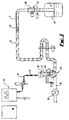
- a pig 10 is shown in use evacuating a pipeline 16 of liquid material F.
- the pipeline 16 is normally used to convey liquid material F (which for the purpose of illustration only will be considered to be a liquid product that is being heat treated in the pipeline 16) from an inlet conduit 38 which supplies the product F from downstream, to a receptacle 40.
- a valve arrangement 42 is provided at the intersection of the inlet conduit 38, the entrance to the pipeline 16 and a pig storage housing 44.
- Pig detecting means 46,48 are provided to detect the presence or absence of a pig 10 in the storage housing 44 and at the output end 50 of the pipeline 16, respectively.
- Heating means (not shown) is provided to heat treat the liquid F in the pipeline, for example to pasteurise it.
- a propellant fluid source 52 such as a compressed air generator or pressurised cleaning liquid source, is connected via a conduit 54 to the storage housing 44 for selective supply of propellant fluid thereto to drive a pig 10 located in the housing 44 down the pipeline 16 as will be described.
- valve arrangement 42 connects the inlet conduit 38 to the pipeline 16 to allow the flow of liquid F pumped by the pump 56 from the conduit 38 along the pipeline 16.
- the storage housing 44 comprising a pig 10 (as shown in dotted outline) is isolated from the pipeline 16 and the propellant fluid source is de-activated.
- liquid F is pasteurised and it is pumped along the pipeline.
- treatment if any, is given to fluid in the pipeline prior to evacuation.
- the pump 56 Upon completion of a production run for the liquid F, the pump 56 is de-activated and the valve arrangement 42 turned to the position shown in Fig. 3 wherein the conduit 38 is isolated from the pipeline 16, and the storage housing 44 is placed in communication with the pipeline 16.
- the propellant fluid source 52 is then activated, and pressurised propellant fluid (indicated by the arrows X) is forced down the conduit 54 into the housing 44 wherein it acts upon the pig 10 to drive it down, through the valve arrangement 42 and along the pipeline 16.
- the reaction or resistance of the fluid F to such movement acts on the leading end 26, and particularly against the surface 34 and thereby compresses the relatively soft leading deformable portion 14 against the relatively rigid portion 12, to cause the deformable portion 14 to bell out or expand particularly in the region of the parts 25 in a lateral direction to form a sealing collar 37 that presses against the inside surface of the pipeline 16 to provide a slidable seal thereagainst.
- the sealirig collar 37 presses against the inside of the surface harder than the relatively non-deformable parts of the device 10.
- the force of the propellant fluid on the end 28 and particularly the surface 36 compresses the deformable portion 14 against the rigid portion 12 to cause the rear deformable portion 14 to bell out to form a sealing collar 37 which presses against the inner surface of the pipeline 16 to provide a second, slidable seal against the inside of the inside of the pipeline 16.
- the force of the propellant fluid F is sufficient to drive the pig 10 in this deformed condition along the pipeline 16, with the respective compressed portions 12 dragging along the inner surface of the pipeline 16, thereby ensuring that little or no residue of liquid F is left behind the pig 10 and hence providing efficient evacuation of fluid F from the pipeline 16.
- the propellant fluid F may be cleaning fluid which further cleans, particularly on a microbial level, the inside of the pipeline 12 following the movement of the pig 10 along the pipeline.
- the external diameter of the pig 10 is sufficiently less than the internal diameter of the pipeline in which it is intended for use, the pig 10 is readily launched into a pipeline for use.
- the magnetic characteristics of the rigid portion 12 enable the position of the pig 12 in the pipeline 16 to be determined, and once the pig 10 reaches the end 50 of the pipeline 16, the second detector 48 signals this, and the propellant fluid source can be de-activated.
- the fluid F evacuated from the pipeline 16 is collected in the receptacle 40 for use or disposal as appropriate.
- the pig 10 provides for more efficient evacuation and cleaning of pipelines 16 than is provided by conventional designs of pig, and the pig 10 could be used to evacuate gases from pipelines 16 as well liquids under appropriate conditions.
Landscapes
- Engineering & Computer Science (AREA)
- General Engineering & Computer Science (AREA)
- Mechanical Engineering (AREA)
- Pipe Accessories (AREA)
- Cleaning In General (AREA)
Claims (22)
- Rohrleitung-Entleerungsvorrichtung (10), welche aufweist: einen relativ starren ersten Abschnitt (12), der in der Vorrichtung im Wesentlichen mittig angeordnet ist und entgegengesetzte Enden (18, 20) hat; und zwei relativ verformbare zweite Abschnitte (14), von denen jeweils einer an jeweils einem der entgegengesetzten Enden des relativ starren Abschnitts (12) angeordnet ist; wobei die relativ verformbaren Abschnitte (14) gegen den starren Abschnitt (12) hin komprimierbar sind, wenn die Vorrichtung (10) durch eine Rohrleitung hindurchgedrückt wird, welche Material enthält, das durch die Reaktion des Materials in der Rohrleitung (16) gegen die durch die Bewegung der Vorrichtung (10) erzeugte Kraft entfernt werden soll, wobei die Kompression ein Verformen der zweiten Abschnitte (14) bewirkt, um die zweiten Abschnitte gegen die Innenseite der Rohrleitung (16) gleitend abzudichten; dadurch gekennzeichnet, dass: der relativ starre Abschnitt (12) und die relativ verformbaren Abschnitte (14) aus demselben Kunststoffmaterial gefertigt sind; der relativ starre Abschnitt (12) außerdem ein magnetisches oder magnetisierbares Material als Pulver oder in körniger Form enthält; und die relativ verformbaren Abschnitte (14) frei von magnetischem oder magnetisierbarem Material sind; wobei der relativ starre Abschnitt und die relativ verformbaren.Abschnitte durch chemische Bindungen zusammengehalten werden, wodurch der relativ starre und die relativ verformbaren Abschnitte eine einstückige Einheit bilden.
- Vorrichtung (10) nach Anspruch 1, dadurch gekennzeichnet, dass die zweiten Abschnitte (14) elastisch derart verformbar sind, dass nach Beseitigung der Druckzustände die Vorrichtung (10) in einen nicht-komprimierten Zustand zurückkehrt.
- Vorrichtung (10) nach Anspruch 1 oder 2, dadurch gekennzeichnet, dass die zweiten Abschnitte (14) dafür ausgelegt sind, um komprimierbar zu sein, um die relaxierte Breite der zweiten Abschnitte in einer Richtung im Wesentlichen senkrecht zur beabsichtigten Bewegungsrichtung der Vorrichtung (10) während des Gebrauchs entlang der Rohrleitung (16) zu erhöhen.
- Vorrichtung (10) nach Anspruch 1, 2 oder 3, dadurch gekennzeichnet, dass die zweiten Abschnitte (14) im Wesentlichen symmetrisch verformbar sind, um eine Abdichtung um die Vorrichtung (10) herum zu erzeugen, um eine im Wesentlichen vollständige gleitbare Abdichtung um die Vorrichtung herum in der Rohrleitung (16) zu erzeugen.
- Vorrichtung (10) nach einem der Ansprüche 1, 2, 3 oder 4, dadurch gekennzeichnet, dass die Abdichtung in Form eines Dichtungskragens (37) vorliegt.
- Vorrichtung (10) nach einem der vorhergehenden Ansprüche, dadurch gekennzeichnet, dass die zweiten Abschnitte (14) sich im Wesentlichen über die gesamte Breite des ersten Abschnitts (12) erstrecken, um einen Dichtungskragen (37) im Wesentlichen an einem Ende des ersten Abschnitts (12) zu erzeugen.
- Vorrichtung (10) nach einem der vorhergehenden Ansprüche, dadurch gekennzeichnet, dass einer der verformbaren Abschnitte (14) an dem Ende angeordnet ist, das im Gebrauch der Vorrichtung vorauseilt, um eine Kompression eines der zweiten Abschnitte (14) zwischen dem zu entfernenden Fluid in der Rohrleitung (16) und dem ersten Abschnitt (12) zu erzeugen.
- Vorrichtung (10) nach Anspruch 7, dadurch gekennzeichnet, dass sich die Vorrichtung an dem einen vorauseilenden Ende verjüngt.
- Vorrichtung (10) nach Anspruch 8, dadurch gekennzeichnet, dass das vorauseilende Ende eine Oberfläche aufweist, die im Wesentlichen senkrecht zur Bewegungsrichtung der Vorrichtung ist, auf welche die Reaktionskräfte des Materials während des Gebrauchs einwirken.
- Vorrichtung (10) nach einem der vorhergehenden Ansprüche, dadurch gekennzeichnet, dass die Vorrichtung (10) im Wesentlichen länglich ist und in der Längsrichtung benutzbar ist.
- Vorrichtung (10) nach einem der vorhergehenden Ansprüche, dadurch gekennzeichnet, dass das magnetische oder magnetisierbare Material ein Metall oder eine Metallverbindung ist.
- Vorrichtung (10) nach einem der vorhergehenden Ansprüche, dadurch gekennzeichnet, dass der erste Abschnitt einen größeren Durchmesser als die zweiten Abschnitte hat, wenn die Vorrichtung in dem relaxierten Zustand ist.
- Vorrichtung (10) nach einem der vorhergehenden Ansprüche, dadurch gekennzeichnet, dass der erste Abschnitt (12) und der zweite Abschnitt (14) in einer flexiblen äußeren Hülle (22) eingeschlossen sind, wobei die Hülle relativ zäh ist, um einen Schutz für den ersten und den zweiten Abschnitt zu erzeugen.
- Vorrichtung (10) nach einem der vorhergehenden Ansprüche, dadurch gekennzeichnet, dass die Vorrichtung im Wesentlichen symmetrisch ist.
- Vorrichtung (10) nach einem der vorhergehenden Ansprüche, dadurch gekennzeichnet, dass die Vorrichtung bidirektional benutzbar ist.
- Verfahren zum Entfernen von Material, gekennzeichnet durch Antreiben einer Entleerungsvorrichtung im Wesentlichen gemäß einem der Ansprüche 1 bis 15 entlang einer Rohrleitung (16), die zu entfernendes Material enthält, wobei die Antriebskraft ausreichend groß ist, um zu bewirken, dass die verformbaren Abschnitte (14) der zu komprimierenden Vorrichtung zwischen der Antriebskraft und der Reaktionskraft des Materials in der Rohrleitung (16) sich verformen, um eine im Wesentlichen gleitende Abdichtung an der Innenseite der Rohrleitung zu bilden, und dass die Vorrichtung entlang der Rohrleitung bewegt wird, um Fluid zu seiner Entfernung entlang der Rohrleitung vor der Vorrichtung herzuschieben.
- Verfahren nach Anspruch 16, dadurch gekennzeichnet, dass die Antriebskraft durch Druckluft erzeugt wird, die hinter der Vorrichtung (10) in die Rohrleitung eingespeist wird.
- Verfahren nach Anspruch 16 oder 17, dadurch gekennzeichnet, dass die Antriebskraft alternativ oder zusätzlich durch eine druckbeaufschlagte Flüssigkeit erzeugt wird.
- Verfahren zum Herstellen einer Rohrleitung-Entleerungsvorrichtung gemäß einem der Ansprüche 1 bis 15, gekennzeichnet durch Gießen eines relativ starren Abschnitts (12) neben zwei relativ verformbaren Abschnitten (14) an entgegengesetzten Enden des relativ starren Abschnitts; Aushärten lassen der Abschnitte miteinander, um chemische Bindungen zwischen dem relativ starren Abschnitt und den relativ verformbaren Abschnitten zu bilden; und Einschließen der Abschnitte in eine Schutzhülle und Aushärten lassen der Hülle an den Abschnitten.
- Verfahren nach Anspruch 19, dadurch gekennzeichnet, dass das Aushärten durch Wärmebehandlung bewirkt wird.
- Verfahren nach Anspruch 19 oder 20, dadurch gekennzeichnet, dass ein oder mehrere magnetische und/oder magnetisierbare Additive dem ersten Abschnitt (12) hinzu gegeben werden, wenn er in einem flüssigen Zustand vor dem Gießen ist, wobei das eine oder die mehreren Additive zu der relativen Steifigkeit des ersten Abschnitts zumindest beitragen.
- Anordnung, welche eine Rohrleitung (12) und eine Rohrleitung-Entleerungsvorrichtung (10) gemäß einem der Ansprüche 1 bis 15 enthält.
Applications Claiming Priority (2)
| Application Number | Priority Date | Filing Date | Title |
|---|---|---|---|
| GB9700936 | 1997-01-17 | ||
| GBGB9700936.9A GB9700936D0 (en) | 1997-01-17 | 1997-01-17 | Evacuating pipelines and apparatus therefor |
Publications (4)
| Publication Number | Publication Date |
|---|---|
| EP0855548A2 EP0855548A2 (de) | 1998-07-29 |
| EP0855548A3 EP0855548A3 (de) | 1998-08-05 |
| EP0855548B1 true EP0855548B1 (de) | 2006-07-05 |
| EP0855548B8 EP0855548B8 (de) | 2006-12-13 |
Family
ID=10806152
Family Applications (1)
| Application Number | Title | Priority Date | Filing Date |
|---|---|---|---|
| EP98300282A Expired - Lifetime EP0855548B8 (de) | 1997-01-17 | 1998-01-15 | Verfahren und Vorrichtung zur Entleerung eines Rohres |
Country Status (4)
| Country | Link |
|---|---|
| US (2) | US6176938B1 (de) |
| EP (1) | EP0855548B8 (de) |
| DE (1) | DE69835115T2 (de) |
| GB (1) | GB9700936D0 (de) |
Families Citing this family (18)
| Publication number | Priority date | Publication date | Assignee | Title |
|---|---|---|---|---|
| GB9700936D0 (en) * | 1997-01-17 | 1997-03-05 | Hygienic Pigging Systems Limit | Evacuating pipelines and apparatus therefor |
| US6527869B1 (en) * | 2000-06-08 | 2003-03-04 | Christopher J. Bourg | Method for cleaning deposits from the interior of pipes |
| DE102004015417A1 (de) * | 2004-03-26 | 2005-10-13 | Putzmeister Ag | Vorrichtung und Verfahren zur Reinigung einer Dickstoffförderleitung |
| US20070151055A1 (en) | 2006-01-04 | 2007-07-05 | 766089 Alberta Ltd. | Pipeline pig brush and brush assembly |
| US7752700B2 (en) * | 2005-09-14 | 2010-07-13 | Diversey, Inc. | Cleaning bullet |
| US7743450B2 (en) * | 2005-09-14 | 2010-06-29 | Diversey, Inc. | Cleaning bullet |
| US20100154153A1 (en) * | 2008-12-24 | 2010-06-24 | 766089 Alberta Ltd. | Pipeline pig brush |
| DE102014102526B4 (de) * | 2014-02-26 | 2017-12-07 | Netzsch-Feinmahltechnik Gmbh | Anlage zur herstellung und / oder aufbereitung von confectionery-massen und verfahren zur herstellung und / oder aufbereitung von confectionery-massen |
| DE102014102529B4 (de) * | 2014-02-26 | 2017-12-07 | Netzsch-Feinmahltechnik Gmbh | Anlage zur herstellung und / oder aufbereitung von confectionery-massen und verfahren zur reinigung einer anlage zur herstellung und / oder aufbereitung von confectionery-massen |
| US10315857B2 (en) * | 2016-04-19 | 2019-06-11 | Ecolab Usa Inc. | Cleaning device for pneumatic conveyance system |
| US10478871B2 (en) | 2016-05-09 | 2019-11-19 | Lawrence Anthony Wiwi | Side-opening sleeve valve |
| US20170320111A1 (en) * | 2016-05-09 | 2017-11-09 | Lawrence Anthony Wiwi | Side-opening sleeve valve |
| US10466134B2 (en) * | 2016-12-20 | 2019-11-05 | Linde Aktiengesellschaft | Methods for detecting leaks in pipelines |
| CN106890828B (zh) * | 2017-03-29 | 2023-05-30 | 成都理工大学 | 一种多功能管具内壁清洁装置及其清洁方法 |
| US10769684B1 (en) * | 2017-10-03 | 2020-09-08 | Wells Fargo Bank, N.A. | Property assessment system with buoyancy adjust device |
| US10668513B2 (en) * | 2018-10-01 | 2020-06-02 | Kyle Hill | Pig receptacle |
| FR3087362B1 (fr) * | 2018-10-19 | 2022-12-16 | Exel Ind | Installation de projection de fluide et procede de deplacement d'un fluide associe |
| CN111156408A (zh) * | 2018-11-08 | 2020-05-15 | 中国石油化工股份有限公司 | 用于储存液体和清除残液的系统 |
Family Cites Families (23)
| Publication number | Priority date | Publication date | Assignee | Title |
|---|---|---|---|---|
| GB392512A (en) | 1930-11-01 | 1933-05-18 | Adolf Brendlin | Improvements in and relating to cleansing apparatus for tubes |
| GB483941A (en) | 1937-02-23 | 1938-04-28 | Ira Talmage Stephens | Improvements in bullets for cleaning tubes |
| US3011197A (en) * | 1957-07-18 | 1961-12-05 | Mobay Chemical Corp | Pipeline cleaning devices |
| US3384512A (en) * | 1966-10-21 | 1968-05-21 | Peoples Dev Inc | Pigging device and detection system |
| US3546642A (en) * | 1968-05-10 | 1970-12-08 | Peoples Gas Light & Coke Co Th | Pigging device |
| US3543323A (en) * | 1968-11-20 | 1970-12-01 | Harry J Girard | Foamed plastic pig for pipe lines |
| US3879790A (en) | 1969-06-23 | 1975-04-29 | Harry J Girard | Pipe line pig |
| US3875606A (en) | 1973-08-15 | 1975-04-08 | Oil States Rubber Co | Foam filled pipeline pig |
| GB1444496A (en) | 1974-09-30 | 1976-07-28 | Oil States Rubber Co | Foam filled pipeline pig |
| US4077079A (en) * | 1976-08-19 | 1978-03-07 | Knapp Mary M | Pipeline pig |
| US4083076A (en) * | 1977-01-14 | 1978-04-11 | Girard Harry J | Pipeline pig with longitudinally incompressible member |
| DE3032532C2 (de) | 1980-08-29 | 1983-11-10 | Hubert 2000 Hamburg Skibowski | Rohrleitungsmolch |
| US4416703A (en) * | 1981-11-20 | 1983-11-22 | Shell Oil Company | System for removing debris from pipelines |
| US4714888A (en) * | 1984-06-11 | 1987-12-22 | French Hartley A | Apparatus for observing the passage of a pig in a pipeline |
| US5032185A (en) * | 1990-05-21 | 1991-07-16 | Knapp Kenneth M | Method and apparatus for removing paraffin from a fouled pipeline |
| DE9111600U1 (de) * | 1991-09-18 | 1991-11-07 | Czekanowsky, Falko, 2081 Appen | Kompressionsmolch |
| BR9202987A (pt) * | 1992-07-31 | 1994-02-01 | Petroleo Brasileiro Sa | Processo para remocao de liquidos em tubulacoes por meio de um piston movel |
| DE4422294C1 (de) * | 1994-06-25 | 1995-08-03 | Samson Ag | Rohrleitungsmolch |
| US5461354A (en) * | 1994-07-14 | 1995-10-24 | Tdw Delaware, Inc. | Magnetic sphere for use in a pipeline |
| DE19513104A1 (de) * | 1995-04-07 | 1996-10-10 | Pfeiffer Chemie Armaturen | Rohrmolch |
| US5795402A (en) * | 1995-07-25 | 1998-08-18 | Hargett, Sr.; Daniel | Apparatus and method for removal of paraffin deposits in pipeline systems |
| GB9700936D0 (en) * | 1997-01-17 | 1997-03-05 | Hygienic Pigging Systems Limit | Evacuating pipelines and apparatus therefor |
| US6067682A (en) * | 1997-07-15 | 2000-05-30 | Tdw Delaware, Inc. | Cup or disc for use as a part of a pipeline pig |
-
1997
- 1997-01-17 GB GBGB9700936.9A patent/GB9700936D0/en active Pending
-
1998
- 1998-01-15 EP EP98300282A patent/EP0855548B8/de not_active Expired - Lifetime
- 1998-01-15 DE DE69835115T patent/DE69835115T2/de not_active Expired - Lifetime
- 1998-01-15 US US09/007,639 patent/US6176938B1/en not_active Expired - Lifetime
-
2000
- 2000-10-30 US US09/699,973 patent/US6438782B1/en not_active Expired - Lifetime
Also Published As
| Publication number | Publication date |
|---|---|
| US6176938B1 (en) | 2001-01-23 |
| EP0855548B8 (de) | 2006-12-13 |
| DE69835115T2 (de) | 2007-02-08 |
| DE69835115D1 (de) | 2006-08-17 |
| EP0855548A2 (de) | 1998-07-29 |
| GB9700936D0 (en) | 1997-03-05 |
| EP0855548A3 (de) | 1998-08-05 |
| US6438782B1 (en) | 2002-08-27 |
Similar Documents
| Publication | Publication Date | Title |
|---|---|---|
| EP0855548B1 (de) | Verfahren und Vorrichtung zur Entleerung eines Rohres | |
| EP0789180A2 (de) | Verfahren zur Innenbeschichtung eines Rohres | |
| US10444191B2 (en) | Pipe pig for inspecting a pipeline | |
| AU677229B2 (en) | Improvements relating to the lining of pipelines and passageways | |
| US7614109B2 (en) | Device for moving a pig through a conduit, such as a pipeline | |
| US5924158A (en) | Pipeline pig | |
| US6249927B1 (en) | Duct-cleaning unit | |
| GB2346422B (en) | A pipe coupling | |
| GB2369871A (en) | Apparatus for testing or isolating a segment of pipe | |
| EP0938964A3 (de) | Auskleidung eines Abzweigrohres und Auskleidungsverfahren | |
| US20150298181A1 (en) | Method and clean-in-place system for conveying tubes | |
| US20050200037A1 (en) | Pipeline pig | |
| SE9100486L (en) | Process for cleaning of pipelines - involves contacting spherical cleaner with inner wall of pipe, with cleaner having pressurised fluid nozzle | |
| US3460180A (en) | Internal cleaning device for pipe lines | |
| CN101761664B (zh) | 节流阀及其在用以清洁泥浆输送管的设备和方法中的应用 | |
| GB2342372A (en) | Apparatus for cleaning well casings or pipes | |
| US5698042A (en) | Method of cleaning furnace headers | |
| WO2000055539A1 (en) | Mains | |
| US5466184A (en) | Device for removing surface air in casings | |
| CN114370543B (zh) | 一种四氯化碳输送管道防堵装置 | |
| US20030070694A1 (en) | Method and apparatus for online and offline cleaning of industrial systems | |
| CA2198103C (en) | Process for renovating pipes | |
| EP0854309A2 (de) | Ventilanordnungen | |
| US20180281031A1 (en) | Method and clean-in-place system for conveying tubes | |
| EP0537239B1 (de) | Verfahren und vorrichtung zum anbringen eines innenrohres in einer bestehenden rohrleitung |
Legal Events
| Date | Code | Title | Description |
|---|---|---|---|
| PUAI | Public reference made under article 153(3) epc to a published international application that has entered the european phase |
Free format text: ORIGINAL CODE: 0009012 |
|
| PUAL | Search report despatched |
Free format text: ORIGINAL CODE: 0009013 |
|
| AK | Designated contracting states |
Kind code of ref document: A2 Designated state(s): BE BE DK DE FR ES IE FR GB GR IE IT LI LU MC NL PT |
|
| AX | Request for extension of the european patent |
Free format text: AL;LT;LV;MK;RO;SI |
|
| AK | Designated contracting states |
Kind code of ref document: A3 Designated state(s): AT BE CH DE DK ES FI FR GB GR IE IT LI LU MC NL PT SE |
|
| AX | Request for extension of the european patent |
Free format text: AL;LT;LV;MK;RO;SI |
|
| PUAL | Search report despatched |
Free format text: ORIGINAL CODE: 0009013 |
|
| AX | Request for extension of the european patent |
Free format text: AL;LT;LV;MK;RO;SI |
|
| RIC1 | Information provided on ipc code assigned before grant |
Free format text: 7F 16L 55/40 A, 7B 08B 9/04 B |
|
| 17P | Request for examination filed |
Effective date: 20001009 |
|
| AKX | Designation fees paid |
Free format text: AT BE CH DE DK ES FI FR GB GR IE IT LI LU MC NL PT |
|
| RBV | Designated contracting states (corrected) |
Designated state(s): BE DE DK ES FR GB IE IT |
|
| 17Q | First examination report despatched |
Effective date: 20040526 |
|
| GRAP | Despatch of communication of intention to grant a patent |
Free format text: ORIGINAL CODE: EPIDOSNIGR1 |
|
| GRAS | Grant fee paid |
Free format text: ORIGINAL CODE: EPIDOSNIGR3 |
|
| GRAA | (expected) grant |
Free format text: ORIGINAL CODE: 0009210 |
|
| AK | Designated contracting states |
Kind code of ref document: B1 Designated state(s): BE DE DK ES FR GB IE IT |
|
| PG25 | Lapsed in a contracting state [announced via postgrant information from national office to epo] |
Ref country code: IT Free format text: LAPSE BECAUSE OF FAILURE TO SUBMIT A TRANSLATION OF THE DESCRIPTION OR TO PAY THE FEE WITHIN THE PRE;WARNING: LAPSES OF ITALIAN PATENTS WITH EFFECTIVE DATE BEFORE 2007 MAY HAVE OCCURRED AT ANY TIME BEFORE 2007. THE CORRECT EFFECTIVE DATE MAY BE DIFFERENT FROM THE ONE RECORDED.SCRIBED TIME-LIMIT Effective date: 20060705 Ref country code: BE Free format text: LAPSE BECAUSE OF FAILURE TO SUBMIT A TRANSLATION OF THE DESCRIPTION OR TO PAY THE FEE WITHIN THE PRESCRIBED TIME-LIMIT Effective date: 20060705 |
|
| REG | Reference to a national code |
Ref country code: GB Ref legal event code: FG4D |
|
| REG | Reference to a national code |
Ref country code: IE Ref legal event code: FG4D |
|
| REF | Corresponds to: |
Ref document number: 69835115 Country of ref document: DE Date of ref document: 20060817 Kind code of ref document: P |
|
| RIN2 | Information on inventor provided after grant (corrected) |
Inventor name: PALMER, THOMAS,C/O HYGIENIC PIGGING SYSTEMS LTD. |
|
| PG25 | Lapsed in a contracting state [announced via postgrant information from national office to epo] |
Ref country code: DK Free format text: LAPSE BECAUSE OF FAILURE TO SUBMIT A TRANSLATION OF THE DESCRIPTION OR TO PAY THE FEE WITHIN THE PRESCRIBED TIME-LIMIT Effective date: 20061005 |
|
| PG25 | Lapsed in a contracting state [announced via postgrant information from national office to epo] |
Ref country code: ES Free format text: LAPSE BECAUSE OF FAILURE TO SUBMIT A TRANSLATION OF THE DESCRIPTION OR TO PAY THE FEE WITHIN THE PRESCRIBED TIME-LIMIT Effective date: 20061016 |
|
| RIN2 | Information on inventor provided after grant (corrected) |
Inventor name: PALMER, THOMAS,C/O HYGIENIC PIGGING SYSTEMS LTD. |
|
| PG25 | Lapsed in a contracting state [announced via postgrant information from national office to epo] |
Ref country code: IE Free format text: LAPSE BECAUSE OF NON-PAYMENT OF DUE FEES Effective date: 20070115 |
|
| PLBE | No opposition filed within time limit |
Free format text: ORIGINAL CODE: 0009261 |
|
| STAA | Information on the status of an ep patent application or granted ep patent |
Free format text: STATUS: NO OPPOSITION FILED WITHIN TIME LIMIT |
|
| 26N | No opposition filed |
Effective date: 20070410 |
|
| REG | Reference to a national code |
Ref country code: FR Ref legal event code: PLFP Year of fee payment: 19 |
|
| PGFP | Annual fee paid to national office [announced via postgrant information from national office to epo] |
Ref country code: GB Payment date: 20151215 Year of fee payment: 19 |
|
| PGFP | Annual fee paid to national office [announced via postgrant information from national office to epo] |
Ref country code: FR Payment date: 20151224 Year of fee payment: 19 |
|
| PGFP | Annual fee paid to national office [announced via postgrant information from national office to epo] |
Ref country code: DE Payment date: 20151218 Year of fee payment: 19 |
|
| REG | Reference to a national code |
Ref country code: DE Ref legal event code: R119 Ref document number: 69835115 Country of ref document: DE |
|
| GBPC | Gb: european patent ceased through non-payment of renewal fee |
Effective date: 20170115 |
|
| REG | Reference to a national code |
Ref country code: FR Ref legal event code: ST Effective date: 20170929 |
|
| PG25 | Lapsed in a contracting state [announced via postgrant information from national office to epo] |
Ref country code: FR Free format text: LAPSE BECAUSE OF NON-PAYMENT OF DUE FEES Effective date: 20170131 |
|
| PG25 | Lapsed in a contracting state [announced via postgrant information from national office to epo] |
Ref country code: DE Free format text: LAPSE BECAUSE OF NON-PAYMENT OF DUE FEES Effective date: 20170801 Ref country code: GB Free format text: LAPSE BECAUSE OF NON-PAYMENT OF DUE FEES Effective date: 20170115 |