EP0855514B1 - Liquid-injected screw compressor and filter - Google Patents
Liquid-injected screw compressor and filter Download PDFInfo
- Publication number
- EP0855514B1 EP0855514B1 EP98200027A EP98200027A EP0855514B1 EP 0855514 B1 EP0855514 B1 EP 0855514B1 EP 98200027 A EP98200027 A EP 98200027A EP 98200027 A EP98200027 A EP 98200027A EP 0855514 B1 EP0855514 B1 EP 0855514B1
- Authority
- EP
- European Patent Office
- Prior art keywords
- liquid
- compressor according
- injected compressor
- shaft
- injected
- Prior art date
- Legal status (The legal status is an assumption and is not a legal conclusion. Google has not performed a legal analysis and makes no representation as to the accuracy of the status listed.)
- Expired - Lifetime
Links
- 239000007788 liquid Substances 0.000 title claims description 51
- 229910052751 metal Inorganic materials 0.000 claims description 14
- 239000002184 metal Substances 0.000 claims description 14
- 238000011144 upstream manufacturing Methods 0.000 claims description 10
- 239000000463 material Substances 0.000 claims description 9
- 210000004209 hair Anatomy 0.000 claims description 8
- 230000001413 cellular effect Effects 0.000 claims description 6
- 239000002657 fibrous material Substances 0.000 claims description 6
- 229910010293 ceramic material Inorganic materials 0.000 claims description 5
- 239000006260 foam Substances 0.000 claims description 5
- 229920002994 synthetic fiber Polymers 0.000 claims description 5
- 239000003365 glass fiber Substances 0.000 claims description 3
- 239000011248 coating agent Substances 0.000 claims 2
- 238000000576 coating method Methods 0.000 claims 2
- 239000002245 particle Substances 0.000 description 10
- 238000000926 separation method Methods 0.000 description 10
- 230000001050 lubricating effect Effects 0.000 description 8
- 239000000203 mixture Substances 0.000 description 5
- 230000000717 retained effect Effects 0.000 description 5
- 229920005830 Polyurethane Foam Polymers 0.000 description 4
- 239000011496 polyurethane foam Substances 0.000 description 4
- 238000009412 basement excavation Methods 0.000 description 3
- PXHVJJICTQNCMI-UHFFFAOYSA-N Nickel Chemical compound [Ni] PXHVJJICTQNCMI-UHFFFAOYSA-N 0.000 description 2
- 238000010276 construction Methods 0.000 description 2
- 238000000151 deposition Methods 0.000 description 2
- 230000000694 effects Effects 0.000 description 2
- 239000004744 fabric Substances 0.000 description 2
- 238000005461 lubrication Methods 0.000 description 2
- 238000000197 pyrolysis Methods 0.000 description 2
- XLYOFNOQVPJJNP-UHFFFAOYSA-N water Substances O XLYOFNOQVPJJNP-UHFFFAOYSA-N 0.000 description 2
- 229910018487 Ni—Cr Inorganic materials 0.000 description 1
- 230000005540 biological transmission Effects 0.000 description 1
- VNNRSPGTAMTISX-UHFFFAOYSA-N chromium nickel Chemical compound [Cr].[Ni] VNNRSPGTAMTISX-UHFFFAOYSA-N 0.000 description 1
- 238000004581 coalescence Methods 0.000 description 1
- 239000012530 fluid Substances 0.000 description 1
- 239000000314 lubricant Substances 0.000 description 1
- 239000006262 metallic foam Substances 0.000 description 1
- 238000000034 method Methods 0.000 description 1
- 229910052759 nickel Inorganic materials 0.000 description 1
- 239000004810 polytetrafluoroethylene Substances 0.000 description 1
- 229920001343 polytetrafluoroethylene Polymers 0.000 description 1
- 239000011148 porous material Substances 0.000 description 1
- 238000003825 pressing Methods 0.000 description 1
- 238000007789 sealing Methods 0.000 description 1
Images

Classifications
-
- B—PERFORMING OPERATIONS; TRANSPORTING
- B01—PHYSICAL OR CHEMICAL PROCESSES OR APPARATUS IN GENERAL
- B01D—SEPARATION
- B01D45/00—Separating dispersed particles from gases or vapours by gravity, inertia, or centrifugal forces
- B01D45/12—Separating dispersed particles from gases or vapours by gravity, inertia, or centrifugal forces by centrifugal forces
- B01D45/14—Separating dispersed particles from gases or vapours by gravity, inertia, or centrifugal forces by centrifugal forces generated by rotating vanes, discs, drums or brushes
-
- B—PERFORMING OPERATIONS; TRANSPORTING
- B01—PHYSICAL OR CHEMICAL PROCESSES OR APPARATUS IN GENERAL
- B01D—SEPARATION
- B01D46/00—Filters or filtering processes specially modified for separating dispersed particles from gases or vapours
- B01D46/24—Particle separators, e.g. dust precipitators, using rigid hollow filter bodies
-
- F—MECHANICAL ENGINEERING; LIGHTING; HEATING; WEAPONS; BLASTING
- F04—POSITIVE - DISPLACEMENT MACHINES FOR LIQUIDS; PUMPS FOR LIQUIDS OR ELASTIC FLUIDS
- F04C—ROTARY-PISTON, OR OSCILLATING-PISTON, POSITIVE-DISPLACEMENT MACHINES FOR LIQUIDS; ROTARY-PISTON, OR OSCILLATING-PISTON, POSITIVE-DISPLACEMENT PUMPS
- F04C29/00—Component parts, details or accessories of pumps or pumping installations, not provided for in groups F04C18/00 - F04C28/00
- F04C29/02—Lubrication; Lubricant separation
- F04C29/026—Lubricant separation
-
- Y—GENERAL TAGGING OF NEW TECHNOLOGICAL DEVELOPMENTS; GENERAL TAGGING OF CROSS-SECTIONAL TECHNOLOGIES SPANNING OVER SEVERAL SECTIONS OF THE IPC; TECHNICAL SUBJECTS COVERED BY FORMER USPC CROSS-REFERENCE ART COLLECTIONS [XRACs] AND DIGESTS
- Y10—TECHNICAL SUBJECTS COVERED BY FORMER USPC
- Y10S—TECHNICAL SUBJECTS COVERED BY FORMER USPC CROSS-REFERENCE ART COLLECTIONS [XRACs] AND DIGESTS
- Y10S418/00—Rotary expansible chamber devices
- Y10S418/01—Non-working fluid separation
-
- Y—GENERAL TAGGING OF NEW TECHNOLOGICAL DEVELOPMENTS; GENERAL TAGGING OF CROSS-SECTIONAL TECHNOLOGIES SPANNING OVER SEVERAL SECTIONS OF THE IPC; TECHNICAL SUBJECTS COVERED BY FORMER USPC CROSS-REFERENCE ART COLLECTIONS [XRACs] AND DIGESTS
- Y10—TECHNICAL SUBJECTS COVERED BY FORMER USPC
- Y10S—TECHNICAL SUBJECTS COVERED BY FORMER USPC CROSS-REFERENCE ART COLLECTIONS [XRACs] AND DIGESTS
- Y10S55/00—Gas separation
- Y10S55/13—Polyurethane filters
-
- Y—GENERAL TAGGING OF NEW TECHNOLOGICAL DEVELOPMENTS; GENERAL TAGGING OF CROSS-SECTIONAL TECHNOLOGIES SPANNING OVER SEVERAL SECTIONS OF THE IPC; TECHNICAL SUBJECTS COVERED BY FORMER USPC CROSS-REFERENCE ART COLLECTIONS [XRACs] AND DIGESTS
- Y10—TECHNICAL SUBJECTS COVERED BY FORMER USPC
- Y10S—TECHNICAL SUBJECTS COVERED BY FORMER USPC CROSS-REFERENCE ART COLLECTIONS [XRACs] AND DIGESTS
- Y10S55/00—Gas separation
- Y10S55/14—Inertia separator
-
- Y—GENERAL TAGGING OF NEW TECHNOLOGICAL DEVELOPMENTS; GENERAL TAGGING OF CROSS-SECTIONAL TECHNOLOGIES SPANNING OVER SEVERAL SECTIONS OF THE IPC; TECHNICAL SUBJECTS COVERED BY FORMER USPC CROSS-REFERENCE ART COLLECTIONS [XRACs] AND DIGESTS
- Y10—TECHNICAL SUBJECTS COVERED BY FORMER USPC
- Y10S—TECHNICAL SUBJECTS COVERED BY FORMER USPC CROSS-REFERENCE ART COLLECTIONS [XRACs] AND DIGESTS
- Y10S55/00—Gas separation
- Y10S55/42—Foam filter materials
Definitions
- the present invention concerns a liquid-injected compressor with at least two cooperating compressor elements which are erected in a housing and of which at least one can be rotated and is bearing-mounted with at least one shaft in the housing, whereby the compressor is provided with an inlet and an outlet which are connected to the inside of the housing.
- liquid-injected compressors in particular screw-type compressors, oil or water is used as a lubricant between the two compressor elements.
- Such a separation system contains an air receiver into which the outlet of the compressor opens tangentially. Due to the centrifugal forces there is a first separation which is reinforced by the gravitational effect caused by the different densities of the gas and the lubricating liquid. The further separation occurs in a coalescence filter.
- Such a separation system is voluminous.
- the air receiver has to be approved and as a sound source it raises the noise level of the compressor.
- GB-A-2.186.030 discloses an oil-injected rotary compressor of the kind defined in the first paragraph.
- the atomised oil mixed with the compressed gas is discharged from the rotor chamber and passes over the motor.
- An oil separator consisting of cones provided with gaps, is mounted on the motor shaft.
- the present invention aims a liquid-injected compressor which does not represent the above-mentioned and other disadvantages and thus enables an efficient separation of the compressed gas and the lubricating liquid without a voluminous separation system being required.
- a shaft of a rotatable compressor element is situated in the outlet in the housing and in that at least one body, in particular a disc, made of material permeable to gas, is fixed on this shaft, forming a filter which practically entirely seals the outlet and only lets the compressed gas through.
- US-A-2.204.814 discloses a piston compressor provided with a centrifugal oil separator located in the crank case breather passage and so arranged to separate oil from the air discharged from the crank case.
- the end cap member of the motor housing is provided with a chamber around the motor shaft, which chamber is in connection by passages with the crank case chamber and by an annular passage with the atmosphere.
- the oil separator comprises three spaced annular plates fixed to the shaft, the outer plates being provided with openings, and porous material between the plates. When the pressure in the crank case exceeds the atmospheric pressure, air is evacuated through the passages and over the rotating oil separator.
- this body may consist of cellular material with open cells, of a brush or of other material which is permeable to gas such as fibrous material and/or a tissue, for example woven metal wire, either or not in combination with a fibrous material such as glass fibre and/or synthetic fibre.
- the body can even be made of several layers surrounding one another, for example an outer ring-shaped layer of woven metal wire and an inner ring-shaped layer made of a combination of woven metal wire and fibrous material.
- the body is preferably situated in a chamber formed of a widening of the outlet.
- In the outlet can be erected two or several bodies which are permeable to gas.
- means can be provided in an embodiment according to the invention to make the flow of compressed gas through the body flow at least partially towards the geometrical axis of rotation of said body.
- the end of the shaft in the outlet is provided with a passage for the compressed air which opens radially in the body on the one hand and which opens in the outlet downstream of said body on the other hand.
- Figure 1 represents a one-stage screw-type compressor which mainly consists of a housing 1 in which two compressor elements 2 and 3 formed of helical rotors are mounted in a rotatable manner.
- the housing 1 consists of various parts which are fixed to one another by means of for example bolts.
- the housing 1 circumscribes an inner room 4 in which the rotating compressor elements 2 and 3 are situated.
- Lubricating liquid i.e. oil or water
- Lubricating liquid is injected in the room 4 on the compressor elements 2 and 3 via a duct 5.
- the rotating compressor element 2 consists of a helical body 6 which is axially provided with a shaft 7, 8 respectively, on both ends.
- the shaft 7 is supported on a bearing 9 which is mounted in the housing 1 and it is connected to a drive, for example the outgoing shaft of a motor or of a transmission, which is not represented in figure 1, mounted in a cabinet 10 which is mounted on the housing 1.
- a drive for example the outgoing shaft of a motor or of a transmission, which is not represented in figure 1, mounted in a cabinet 10 which is mounted on the housing 1.
- the shaft 8 is bearing-mounted in a ball bearing 11 which is incorporated in the housing 1.
- the rotating compressor element 3 contains a helical body 12 and a shaft 13, 14 respectively on both ends thereof.
- the shaft 13 is bearing-mounted in a bearing 15 which is fixed in the housing 1 on the side of the cabinet 10.
- the shaft 14 is bearing-mounted in a ball bearing 16 which is incorporated in the housing 1.
- This shaft 14 extends with an elongated end 14A past the ball bearing 16, namely in a round chamber 17 which is formed in an end wall of the housing 1, which end wall is thicker on the side of the ball bearings 11 and 16 than on the opposite side.
- This chamber 17 is part of the outlet 17-18-19.
- the part 18 of the outlet connects the chamber 17 to the room 4, in the middle of the end wall on the high-pressure side between the bodies 6 and 12, whereas the part 19 of the outlet, which has a smaller cross section than the chamber 17, connects this chamber 17 to the outside of the housing 1.
- this part 18 may open tangentially in the chamber 17, for example on the top side opposite the cylindrical outer surface of the body 20.
- a body 20 in the shape of a round disc, made of cellular material with open cells, on the elongated end 14A of the shaft 14.
- the diameter of the body 20 is smaller than the diameter of the chamber 17 but larger than the diameter of the part 19 of the outlet 17-18-19, which is almost entirely sealed by the body 20.
- the body 20 has a sufficiently low flow resistance in order to let gas, in particular gas or air under pressure, through.
- This body 20 preferably consists of a hard foam made of synthetic material, metal or ceramic material.
- a very suitable material for the body 20 is a metal foam made by depositing a metal layer, for example nickel or nickel chromium, by means of a galvanic process on a polyurethane foam and by subsequently removing this polyurethane foam by means of pyrolysis, or a foam of ceramic material made by depositing a ceramic material on a polyurethane foam and by subsequently thermally removing this polyurethane foam, for example by means of pyrolysis.
- a metal foam made by depositing a metal layer, for example nickel or nickel chromium, by means of a galvanic process on a polyurethane foam and by subsequently removing this polyurethane foam by means of pyrolysis
- a foam of ceramic material made by depositing a ceramic material on a polyurethane foam and by subsequently thermally removing this polyurethane foam, for example by means of pyrolysis.
- a little discharge duct 21 which extends outside the housing 1 and onto which a pipe to a cooler can be connected.
- an inlet 22 for the supply of the gas to be compressed to the room 4 extends on the opposite side of the outlet 17-18-19.
- the working of the compressor is simple and as follows.
- the body 6 is rotated via the shaft 7, which rotates the body 12 in turn.
- the gas to be compressed is brought in the room 4 via the inlet 22 and is compressed by the compressor elements 2 and 3.
- the compressed gas is discharged via the outlet 17-18-19 as indicated by the arrows 23.
- This gas hereby flows through the rotating body 20 which is entirely incorporated in the housing 1, where the lubricating liquid particles situated in the gas are stopped and are radially flung out of the body 20 as indicated by the arrows 24.
- the compressor of which a part is represented in figure 2 differs from the one represented in figure 1 in that means are provided to make the compressed gas in the body 20 mainly flow in the direction of the shaft 14 and thus towards the geometrical axis of rotation of the body 20.
- These means consist of a ring-shaped plate 25 which completely covers the side of the body 20 which is directed upstream and thus towards the part 18 of the outlet 17-18-19, and which is fixed against this body 20, for example glued onto it, and of a second ring-shaped plate 26 which is fixed to the opposite side of the body 20 but which only covers the outer part of this side.
- the compressed gas flows via the chamber 17 of the outlet 17-18-19 and the outer edge of the body 20 in this body 20 and leaves the latter in the vicinity of the shaft 14 after the separation of the liquid particles which are radially flung outward.
- the embodiment of the one-stage screw-type compressor as represented in figure 3 mainly differs from the embodiment according to figure 1 in that the body 20 has another design.
- this body is formed of a round, disc-shaped brush with almost radially directed hairs 27.
- a core 28 for example a U-shaped groove in which the hairs 27 are clamped.
- This core 28 is fixed on the elongated end 14A of the shaft 14, for example glued, soldered or clamped onto it.
- the compressed gas flows through the hairs 27 which form a filter. Liquid particles are stopped by the brush and are radially flung away when the shaft 14 rotates, after which they are collected in the chamber 17.
- the flow of the gas through the body 20 and thus the hairs 27 is somewhat directed in the radial sense by means of a ring-shaped radial wall 29 which is provided on the upstream side of this body 20 on the elongated end 14A of the shaft 14, whereas the part 19 of the outlet 17-18-19 only opens centrally in this body 20.
- the body 20 On the upstream side, the body 20 may be confined to this end by a radial wall which reaches as of the outer perimeter up to a distance from the shaft 14.
- the embodiment of the compressor represented in figure 4 mainly differs from the embodiment represented in figure 2 in that the body 20 has a different composition on the one hand and in that the means for guiding the flow of compressed gas radially through this body 20 have a different construction on the other hand, so that the compressed gas cannot flow between the body and the downstream wall of the chamber 17 via the play.
- the body 20 is formed of two ring-shaped layers 30 and 31 surrounding one another.
- the outer ring-shaped layer 30 consists of woven metal wire.
- the inner ring-shaped layer 31 is formed of a combination of woven metal wire which is more tightly woven than the metal wire of the layer 30 and the synthetic fibres.
- These synthetic fibres can be entirely or partly replaced by glass fibres.
- the means for directing the flow radially through the body 20 contain a housing 32 in the shape of a hollow ring which surrounds the body 20 and which is connected to the end 14A of the shaft 14.
- this end 14A is provided with a passage 33-34 for the compressed air, namely an axial excavation 33 which opens in the free end of the shaft 14 on the one hand and thus in the downstream part 19 of the outlet 17-18-19 and in the inside of the housing 32 on the other hand, via openings 34 in the wall of the excavation 33, and as a result in the inner layer 31 of the body 20.
- This housing 32 consists of two side walls 35 and 36 directed radially on the shaft 14 and a cylindrical outer wall 37 situated in between which surrounds the body 20 concentrically.
- the upstream side wall 35 is provided with openings 38 opposite the outer layer 30, whereas the outer wall 37 is provided with openings 39 which open in the chamber 17.
- a lip-shaped seal 40 in the ring-shaped opening between the end 14A of the shaft 14 and the housing 1 of the compressor.
- this lip-shaped seal 40 is preferably made of PTFE.
- This lip-shaped seal 40 may be of what is called the reverse type, i.e. of the type which is lifted when the shaft 14 rotates due to the small pressure difference over the body 20, so that there is no contact or a minimal contact between the lip-shaped seal 40 and the shaft 14.
- the metal wire cloth of this layer collects a large part, usually up to 99.99 % by weight of the liquid which is flung away by the centrifugal force into the chamber 17 and which is discharged via the discharge duct 21.
- the air which still contains small liquid particles further flows radially through the body 20 and thus through the inner layer 31, where said particles are retained.
- the purified air leaves the body 20 through the openings 34 in the end 14A and flows via the excavation 33 in this end to the part 19 of the outlet 17-18-19.
- the two layers 30 and 31 a good separation is combined with a restricted pressure drop. If the body 20 would consist entirely of metal wire cloth with a relatively low density, the fine liquid particles would not be retained. If however, the body 20 would entirely consist of fibrous material with a relatively high density, the pressure drop would be high due to the long way and the high flow rate of the air, which would reduce the energy output of the compressor.
- the lip-shaped seal 40 Thanks to the lip-shaped seal 40, the play between the body 20 surrounded by its housing 32 and the housing 1 of the compressor can be made sufficiently large.
- the sealing diameter is minimal. Since the diameter of this end 14A can be made very precisely, the pressing of the lip-shaped seal 40 can be easily kept under control.
- the embodiment as represented in figure 5 differs from the above-described embodiment in that in the chamber 17, but upstream of the body 20 in the housing 32, is provided an extra body 41 in the shape of a brush with hairs 27 as in the embodiment according to figure 3.
- the mixture of air and liquid penetrates into the double-layered body 20 through the openings 38 in the housing 32, it flows through the hairs 27 of the body 41, where the major part of the liquid, for example up to 99.9 % by weight is retained, so that only the fine liquid particles still have to be retained in the body 41.
- the body 20 could possibly only consist of the layer 31 or it could be made of cellular material with open cells as in the embodiment according to figures 1 and 2.
- the body 41 can also be added in this embodiment according to figures 1 and 2 and thus be applied without the air flowing through the shaft 14.
- an air receiver or such for separating the lubricating liquid To the compressor of none of the above-described embodiments must be connected an air receiver or such for separating the lubricating liquid.
- the liquid separator which consists of the rotating body 20 in the chamber 17 is entirely incorporated in the housing 1, so that a compact whole is obtained which can be produced in an economical manner.
- a major additional advantage of this construction is obtained in that the body 20 deadens the noise to a large extent, so that the noise level in the outlet pipe which is connected to the part 19 of the outlet is significantly reduced.
- the body 20 can be mounted on a shaft 8 of the compressor element 2, in which case the shaft 8 must have an elongated end which reaches into the outlet 17-18-19.
- the invention is not restricted to screw-type compressors, but it can also be applied to other liquid-injected compressors, provided they have a rotating shaft in the outlet upon which a cellular body or a brush can be mounted, such as for example a spiral compressor.
- the compressor can also be a multi-stage compressor.
- a body 20 may be provided in the outlet of the first stage as well as in the outlet of the second or subsequent stage, or also in the outlets of all the stages.
Landscapes
- Chemical & Material Sciences (AREA)
- Chemical Kinetics & Catalysis (AREA)
- Engineering & Computer Science (AREA)
- Mechanical Engineering (AREA)
- General Engineering & Computer Science (AREA)
- Structures Of Non-Positive Displacement Pumps (AREA)
- Applications Or Details Of Rotary Compressors (AREA)
- Filtering Of Dispersed Particles In Gases (AREA)
Description
- The present invention concerns a liquid-injected compressor with at least two cooperating compressor elements which are erected in a housing and of which at least one can be rotated and is bearing-mounted with at least one shaft in the housing, whereby the compressor is provided with an inlet and an outlet which are connected to the inside of the housing.
- With liquid-injected compressors, in particular screw-type compressors, oil or water is used as a lubricant between the two compressor elements.
- In the compressed gas, usually air, are situated particles of this lubricating liquid, which is unacceptable for many applications.
- That is why a separation system is connected to such known compressors to separate the lubricating liquid from the compressed gas.
- Such a separation system contains an air receiver into which the outlet of the compressor opens tangentially. Due to the centrifugal forces there is a first separation which is reinforced by the gravitational effect caused by the different densities of the gas and the lubricating liquid. The further separation occurs in a coalescence filter.
- Such a separation system is voluminous. Moreover, the air receiver has to be approved and as a sound source it raises the noise level of the compressor.
- GB-A-2.186.030 discloses an oil-injected rotary compressor of the kind defined in the first paragraph. The atomised oil mixed with the compressed gas is discharged from the rotor chamber and passes over the motor. An oil separator, consisting of cones provided with gaps, is mounted on the motor shaft.
- The present invention aims a liquid-injected compressor which does not represent the above-mentioned and other disadvantages and thus enables an efficient separation of the compressed gas and the lubricating liquid without a voluminous separation system being required.
- This aim is reached according to the invention in that a shaft of a rotatable compressor element is situated in the outlet in the housing and in that at least one body, in particular a disc, made of material permeable to gas, is fixed on this shaft, forming a filter which practically entirely seals the outlet and only lets the compressed gas through.
- The flow resistance of this body for the compressed gas is sufficiently low in order to let the gas under pressure through. Fluid particles, however, are retained on the body and, due to its rotation, are radially flung away at high speed and are collected.
- US-A-2.204.814 discloses a piston compressor provided with a centrifugal oil separator located in the crank case breather passage and so arranged to separate oil from the air discharged from the crank case. The end cap member of the motor housing is provided with a chamber around the motor shaft, which chamber is in connection by passages with the crank case chamber and by an annular passage with the atmosphere. The oil separator comprises three spaced annular plates fixed to the shaft, the outer plates being provided with openings, and porous material between the plates. When the pressure in the crank case exceeds the atmospheric pressure, air is evacuated through the passages and over the rotating oil separator.
- According to the invention, this body may consist of cellular material with open cells, of a brush or of other material which is permeable to gas such as fibrous material and/or a tissue, for example woven metal wire, either or not in combination with a fibrous material such as glass fibre and/or synthetic fibre.
- The body can even be made of several layers surrounding one another, for example an outer ring-shaped layer of woven metal wire and an inner ring-shaped layer made of a combination of woven metal wire and fibrous material.
- Thus, a too large pressure drop in the body can be avoided.
- The body is preferably situated in a chamber formed of a widening of the outlet.
- In the outlet can be erected two or several bodies which are permeable to gas.
- In order to make the body rotate with blank contact, an axial play is required between said body and the walls of the outlet of the chamber in which it is provided. This play must also absorb tolerances, thermal expansions and the axial turn of the body. Given the high speed, the contact of the body with a wall would cause much wear, especially on the side of the outlet of the body, as there is little lubrication there.
- Thanks to said play, a part of the air/liquid mixture can end up directly in the outlet, which has a negative effect on the liquid separation. When the compressor comes to a standstill, liquid situated on the walls around the body may drip along this body via the play and will be carried along with the air when the compressor is started up again.
- In order to remedy these disadvantages, means can be provided in an embodiment according to the invention to make the flow of compressed gas through the body flow at least partially towards the geometrical axis of rotation of said body.
- Preferably, the end of the shaft in the outlet is provided with a passage for the compressed air which opens radially in the body on the one hand and which opens in the outlet downstream of said body on the other hand.
- In order to better explain the characteristics of the invention, the following preferred embodiment of a liquid-injected compressor according to the invention is described as an example only without being limitative in any way, with reference to the accompanying drawings, in which:
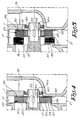
- figure 1 schematically represents a section of a compressor according to the invention;
- figure 2 shows the part which is indicated by F2 in figure 1, but with reference to another embodiment of the invention;
- figure 3 shows the part of figure 2, but with reference to yet another embodiment;
- figures 4 and 5 each show a part of the compressor analogous to that in figures 2 and 3, but with reference to yet other embodiments.
-
- Figure 1 represents a one-stage screw-type compressor which mainly consists of a
housing 1 in which twocompressor elements 2 and 3 formed of helical rotors are mounted in a rotatable manner. - In view of the design, the
housing 1 consists of various parts which are fixed to one another by means of for example bolts. - The
housing 1 circumscribes aninner room 4 in which the rotatingcompressor elements 2 and 3 are situated. - Lubricating liquid, i.e. oil or water, is injected in the
room 4 on thecompressor elements 2 and 3 via aduct 5. - The rotating
compressor element 2 consists of ahelical body 6 which is axially provided with ashaft 7, 8 respectively, on both ends. - The shaft 7 is supported on a
bearing 9 which is mounted in thehousing 1 and it is connected to a drive, for example the outgoing shaft of a motor or of a transmission, which is not represented in figure 1, mounted in acabinet 10 which is mounted on thehousing 1. - The
shaft 8 is bearing-mounted in a ball bearing 11 which is incorporated in thehousing 1. - In an analogous manner, the rotating compressor element 3 contains a
helical body 12 and ashaft - The
shaft 13 is bearing-mounted in abearing 15 which is fixed in thehousing 1 on the side of thecabinet 10. - On the other side, the
shaft 14 is bearing-mounted in a ball bearing 16 which is incorporated in thehousing 1. - This
shaft 14 extends with anelongated end 14A past the ball bearing 16, namely in around chamber 17 which is formed in an end wall of thehousing 1, which end wall is thicker on the side of theball bearings - This
chamber 17 is part of the outlet 17-18-19. Thepart 18 of the outlet connects thechamber 17 to theroom 4, in the middle of the end wall on the high-pressure side between thebodies part 19 of the outlet, which has a smaller cross section than thechamber 17, connects thischamber 17 to the outside of thehousing 1. - Instead of the representation in figure 1, this
part 18 may open tangentially in thechamber 17, for example on the top side opposite the cylindrical outer surface of thebody 20. - In the
chamber 17 is fixed abody 20 in the shape of a round disc, made of cellular material with open cells, on theelongated end 14A of theshaft 14. - The diameter of the
body 20 is smaller than the diameter of thechamber 17 but larger than the diameter of thepart 19 of the outlet 17-18-19, which is almost entirely sealed by thebody 20. - The
body 20 has a sufficiently low flow resistance in order to let gas, in particular gas or air under pressure, through. - This
body 20 preferably consists of a hard foam made of synthetic material, metal or ceramic material. - A very suitable material for the
body 20 is a metal foam made by depositing a metal layer, for example nickel or nickel chromium, by means of a galvanic process on a polyurethane foam and by subsequently removing this polyurethane foam by means of pyrolysis, or a foam of ceramic material made by depositing a ceramic material on a polyurethane foam and by subsequently thermally removing this polyurethane foam, for example by means of pyrolysis. - To the
chamber 17 is connected alittle discharge duct 21 which extends outside thehousing 1 and onto which a pipe to a cooler can be connected. - Through the
housing 1, aninlet 22 for the supply of the gas to be compressed to theroom 4 extends on the opposite side of the outlet 17-18-19. - The working of the compressor is simple and as follows.
- By means of the drive, the
body 6 is rotated via the shaft 7, which rotates thebody 12 in turn. - The gas to be compressed is brought in the
room 4 via theinlet 22 and is compressed by thecompressor elements 2 and 3. The compressed gas is discharged via the outlet 17-18-19 as indicated by thearrows 23. - This gas hereby flows through the
rotating body 20 which is entirely incorporated in thehousing 1, where the lubricating liquid particles situated in the gas are stopped and are radially flung out of thebody 20 as indicated by thearrows 24. - These liquid particles are collected at the bottom of the
chamber 17 and they are discharged to a cooler via thedischarge duct 21 before they are added to the injected lubricating liquid again. - The compressor of which a part is represented in figure 2 differs from the one represented in figure 1 in that means are provided to make the compressed gas in the
body 20 mainly flow in the direction of theshaft 14 and thus towards the geometrical axis of rotation of thebody 20. - These means consist of a ring-shaped
plate 25 which completely covers the side of thebody 20 which is directed upstream and thus towards thepart 18 of the outlet 17-18-19, and which is fixed against thisbody 20, for example glued onto it, and of a second ring-shapedplate 26 which is fixed to the opposite side of thebody 20 but which only covers the outer part of this side. - The compressed gas flows via the
chamber 17 of the outlet 17-18-19 and the outer edge of thebody 20 in thisbody 20 and leaves the latter in the vicinity of theshaft 14 after the separation of the liquid particles which are radially flung outward. - The embodiment of the one-stage screw-type compressor as represented in figure 3 mainly differs from the embodiment according to figure 1 in that the
body 20 has another design. - Instead of a foam disc, this body is formed of a round, disc-shaped brush with almost radially directed
hairs 27. - These hairs are caught in a
core 28, for example a U-shaped groove in which thehairs 27 are clamped. Thiscore 28 is fixed on theelongated end 14A of theshaft 14, for example glued, soldered or clamped onto it. - The compressed gas flows through the
hairs 27 which form a filter. Liquid particles are stopped by the brush and are radially flung away when theshaft 14 rotates, after which they are collected in thechamber 17. - The flow of the gas through the
body 20 and thus thehairs 27 is somewhat directed in the radial sense by means of a ring-shapedradial wall 29 which is provided on the upstream side of thisbody 20 on theelongated end 14A of theshaft 14, whereas thepart 19 of the outlet 17-18-19 only opens centrally in thisbody 20. On the upstream side, thebody 20 may be confined to this end by a radial wall which reaches as of the outer perimeter up to a distance from theshaft 14. - The embodiment of the compressor represented in figure 4 mainly differs from the embodiment represented in figure 2 in that the
body 20 has a different composition on the one hand and in that the means for guiding the flow of compressed gas radially through thisbody 20 have a different construction on the other hand, so that the compressed gas cannot flow between the body and the downstream wall of thechamber 17 via the play. - The
body 20 is formed of two ring-shapedlayers - The outer ring-shaped
layer 30 consists of woven metal wire. The inner ring-shapedlayer 31 is formed of a combination of woven metal wire which is more tightly woven than the metal wire of thelayer 30 and the synthetic fibres. - These synthetic fibres can be entirely or partly replaced by glass fibres.
- Instead of the above-mentioned
plates body 20 contain ahousing 32 in the shape of a hollow ring which surrounds thebody 20 and which is connected to theend 14A of theshaft 14. - Moreover, this
end 14A is provided with a passage 33-34 for the compressed air, namely anaxial excavation 33 which opens in the free end of theshaft 14 on the one hand and thus in thedownstream part 19 of the outlet 17-18-19 and in the inside of thehousing 32 on the other hand, viaopenings 34 in the wall of theexcavation 33, and as a result in theinner layer 31 of thebody 20. - This
housing 32 consists of twoside walls shaft 14 and a cylindricalouter wall 37 situated in between which surrounds thebody 20 concentrically. - The
upstream side wall 35 is provided with openings 38 opposite theouter layer 30, whereas theouter wall 37 is provided withopenings 39 which open in thechamber 17. - Upstream of the
body 20 and thehousing 32 is provided a lip-shapedseal 40 in the ring-shaped opening between theend 14A of theshaft 14 and thehousing 1 of the compressor. - Since there is little lubrication on the lip-shaped
seal 40 and since the operating temperature may rise to 120°C in the outlet 17-18-19, this lip-shapedseal 40 is preferably made of PTFE. - This lip-shaped
seal 40 may be of what is called the reverse type, i.e. of the type which is lifted when theshaft 14 rotates due to the small pressure difference over thebody 20, so that there is no contact or a minimal contact between the lip-shapedseal 40 and theshaft 14. - When a mixture of compressed air and a mass of liquid therein, which may be 6 to 8 times the mass of air, is pressed in the outlet 17-18-19, this mixture penetrates through the openings 38 of the
housing 32 in theouter layer 30 of thebody 20. - The metal wire cloth of this layer collects a large part, usually up to 99.99 % by weight of the liquid which is flung away by the centrifugal force into the
chamber 17 and which is discharged via thedischarge duct 21. - The air which still contains small liquid particles further flows radially through the
body 20 and thus through theinner layer 31, where said particles are retained. - The purified air leaves the
body 20 through theopenings 34 in theend 14A and flows via theexcavation 33 in this end to thepart 19 of the outlet 17-18-19. - Thanks to the two
layers body 20 would consist entirely of metal wire cloth with a relatively low density, the fine liquid particles would not be retained. If however, thebody 20 would entirely consist of fibrous material with a relatively high density, the pressure drop would be high due to the long way and the high flow rate of the air, which would reduce the energy output of the compressor. - Thanks to the lip-shaped
seal 40, the play between thebody 20 surrounded by itshousing 32 and thehousing 1 of the compressor can be made sufficiently large. - As the lip-shaped
seal 40 surrounds theend 14A, the sealing diameter is minimal. Since the diameter of thisend 14A can be made very precisely, the pressing of the lip-shapedseal 40 can be easily kept under control. - The embodiment as represented in figure 5 differs from the above-described embodiment in that in the
chamber 17, but upstream of thebody 20 in thehousing 32, is provided anextra body 41 in the shape of a brush withhairs 27 as in the embodiment according to figure 3. - Before the mixture of air and liquid penetrates into the double-layered
body 20 through the openings 38 in thehousing 32, it flows through thehairs 27 of thebody 41, where the major part of the liquid, for example up to 99.9 % by weight is retained, so that only the fine liquid particles still have to be retained in thebody 41. - According to this embodiment, the
body 20 could possibly only consist of thelayer 31 or it could be made of cellular material with open cells as in the embodiment according to figures 1 and 2. - Moreover, the
body 41 can also be added in this embodiment according to figures 1 and 2 and thus be applied without the air flowing through theshaft 14. - To the compressor of none of the above-described embodiments must be connected an air receiver or such for separating the lubricating liquid. The liquid separator which consists of the
rotating body 20 in thechamber 17 is entirely incorporated in thehousing 1, so that a compact whole is obtained which can be produced in an economical manner. - A major additional advantage of this construction is obtained in that the
body 20 deadens the noise to a large extent, so that the noise level in the outlet pipe which is connected to thepart 19 of the outlet is significantly reduced. - Instead of on a
shaft 14 of the compressor element 3, thebody 20 can be mounted on ashaft 8 of thecompressor element 2, in which case theshaft 8 must have an elongated end which reaches into the outlet 17-18-19. - The invention is not restricted to screw-type compressors, but it can also be applied to other liquid-injected compressors, provided they have a rotating shaft in the outlet upon which a cellular body or a brush can be mounted, such as for example a spiral compressor.
- The compressor can also be a multi-stage compressor. A
body 20 may be provided in the outlet of the first stage as well as in the outlet of the second or subsequent stage, or also in the outlets of all the stages. - The present invention is by no means limited to the above-described embodiments represented in the accompanying drawings; on the contrary, such liquid-injected compressors can be made in all sorts of variants while still remaining within the scope of the invention.
Claims (22)
- Liquid-injected compressor with at least two cooperating compressor elements (2 and 3) which are erected in a housing (1) and of which at least one can be rotated and is bearing-mounted with a shaft (7, 8, 13, 14) in the housing (1), whereby the compressor is provided with an inlet (22) and an outlet (17-18-19) which are connected to the inside of the housing (1), characterized in that a shaft (14) of a rotatable compressor element (3) is situated in the outlet (17-18-19) in the housing (1) and in that at least one body (20 or 41) made of material which is permeable to gas, is fixed on this shaft (14), forming a filter which practically entirely seals the outlet (17-18-19) and only lets the compressed gas through.
- Liquid-injected compressor according to claim 1, characterized in that the body (20 or 41) has the shape of a disc.
- Liquid-injected compressor according to claim 1 or 2, characterized in that the body (20 or 41) is situated in a chamber (17) formed of a widening of the outlet (17-18-19).
- Liquid-injected compressor according to claim 3, characterized in that a little discharge duct (21) is connected to the chamber (17).
- Liquid-injected compressor according to any of claims 1 to 4, characterized in that the body (20 or 41) is made of metal, synthetic material or ceramic material.
- Liquid-injected compressor according to any of the preceding claims, characterized in that the body (20) is made of cellular material with open cells.
- Liquid-injected compressor according to claim 6, characterized in that the body (20) was made by first coating synthetic foam with open cells with metal in a galvanic manner or by coating it with ceramic material and by subsequently thermally removing the synthetic foam.
- Liquid-injected compressor according to any of claims 1 to 5, characterized in that the body (20 or 41) is a brush.
- Liquid-injected compressor according to claim 8, characterized in that the body (20 or 41) is a brush with almost radially directed hairs (27).
- Liquid-injected compressor according to any of claims 1 to 5, characterized in that the body (20 or 41) is made of fibrous material and/or a tissue.
- Liquid-injected compressor according to any of the preceding claims, characterized in that the body (20 or 41) contains at least two layers (30 and 31) surrounding one another.
- Liquid-injected compressor according to any of claims 10 and 11, characterized in that the outer layer (30) of the body (20 or 41) is made of woven metal wire and in that the inner layer (31) is made of a combination of woven metal wire and synthetic or glass fibre.
- Liquid-injected compressor according to any of the preceding claims, characterized in that it contains two bodies (20 and 41) which are permeable to gas which are fixed on the shaft (14) one after the other.
- Liquid-injected compressor according to claim 12, characterized in that the upstream body (41) has a smaller density than the other body (20).
- Liquid-injected compressor according to claim 8, 10 and 14, characterized in that the upstream body (41) is a brush, whereas the other body (20) is made of cellular material with open cells or of fibrous material and/or a tissue.
- Liquid-injected compressor according to any of the preceding claims, characterized in that it is a screw-type compressor and in that the body (20) is mounted on a shaft (14) on one end of any of the helical compressor elements (2 and 3).
- Liquid-injected compressor according to any of the preceding claims, characterized in that means are provided to make the compressed gas in the body (20 or 41) flow at least partially in the direction of the geometrical axis of rotation of this body (20 or 41).
- Liquid-injected compressor according to claim 17, characterized in that the above-mentioned means contain a plate (25) or a side wall (35) of a housing (32) of the body (20 or 41) which at least partially covers the side of the body (20 or 41) which is directed upstream.
- Liquid-injected compressor according to claim 18, characterized in that the above-mentioned means contain a plate (25) or side wall (35) which at least partially covers the side of the body (20) which is directed upstream and a plate (26) which partially covers the opposite side of the body (20).
- Liquid-injected compressor according to claim 17 or 18, characterized in that the end (14A) of the shaft (14) in the outlet (17-18-19) is provided with a passage (33-34) for compressed air which opens radially in the body (20) on the one hand and which opens in the outlet (17-18-19) downstream of said body (20) on the other hand.
- Liquid-injected compressor according to claim 20, characterized in that the body (20) is sealed by a plate or side wall (36) on the downstream side.
- Liquid-injected compressor according to claim 20 or 21, characterized in that, downstream of the body (20), the space between the housing (1) and the shaft (14) is secured by a seal, for example a lip-shaped seal (40).
Applications Claiming Priority (2)
| Application Number | Priority Date | Filing Date | Title |
|---|---|---|---|
| BE9700036A BE1010851A3 (en) | 1997-01-15 | 1997-01-15 | LIQUID INJECTED COMPRESSOR at least two cooperating compressor elements. |
| BE9700036 | 1997-01-15 |
Publications (2)
| Publication Number | Publication Date |
|---|---|
| EP0855514A1 EP0855514A1 (en) | 1998-07-29 |
| EP0855514B1 true EP0855514B1 (en) | 2003-04-02 |
Family
ID=3890266
Family Applications (1)
| Application Number | Title | Priority Date | Filing Date |
|---|---|---|---|
| EP98200027A Expired - Lifetime EP0855514B1 (en) | 1997-01-15 | 1998-01-08 | Liquid-injected screw compressor and filter |
Country Status (6)
| Country | Link |
|---|---|
| US (1) | US6109902A (en) |
| EP (1) | EP0855514B1 (en) |
| JP (1) | JPH10220379A (en) |
| BE (1) | BE1010851A3 (en) |
| DE (1) | DE69812736T2 (en) |
| ES (1) | ES2200264T3 (en) |
Cited By (1)
| Publication number | Priority date | Publication date | Assignee | Title |
|---|---|---|---|---|
| CN109469618A (en) * | 2018-11-29 | 2019-03-15 | 周焱春 | A kind of screw air compressor |
Families Citing this family (18)
| Publication number | Priority date | Publication date | Assignee | Title |
|---|---|---|---|---|
| US6499971B2 (en) * | 2000-12-01 | 2002-12-31 | Bristol Compressors, Inc. | Compressor utilizing shell with low pressure side motor and high pressure side oil sump |
| US6953490B2 (en) * | 2002-12-16 | 2005-10-11 | Carrier Corporation | In-line oil separator |
| DE10306547B4 (en) * | 2003-02-17 | 2005-08-04 | Aerzener Maschinenfabrik Gmbh | Rotary engine |
| WO2007050045A1 (en) * | 2005-10-25 | 2007-05-03 | Mikro Makina Sanayi Ve Ticaret A.S | Separator in separator |
| DE102010055798A1 (en) * | 2010-08-26 | 2012-03-01 | Vacuubrand Gmbh + Co Kg | vacuum pump |
| JP5632700B2 (en) * | 2010-10-19 | 2014-11-26 | 三浦工業株式会社 | Heat recovery system |
| JP5527396B1 (en) * | 2012-12-17 | 2014-06-18 | ダイキン工業株式会社 | Screw compressor |
| GB2542717A (en) | 2014-06-10 | 2017-03-29 | Vmac Global Tech Inc | Methods and apparatus for simultaneously cooling and separating a mixture of hot gas and liquid |
| AU2017261926B2 (en) | 2016-05-12 | 2021-04-08 | Golden Renewable Energy, LLC | Cyclonic condensing and cooling system |
| US10436525B2 (en) | 2016-05-12 | 2019-10-08 | Golden Renewable Energy, LLC | Cyclonic cooling system |
| BR112018076425A2 (en) * | 2016-06-21 | 2019-04-09 | Golden Renewable Energy, LLC | material handling equipment |
| KR20220070548A (en) | 2016-06-21 | 2022-05-31 | 브레이븐 인바이론멘탈 엘엘씨 | Char separator and method |
| CN109563415A (en) * | 2016-06-21 | 2019-04-02 | 戈登可再生能源有限公司 | Bag press machine feeds device assembly |
| US10961062B2 (en) | 2016-06-21 | 2021-03-30 | Golden Renewable Energy, LLC | Bag press feeder assembly |
| US20170361268A1 (en) | 2016-06-21 | 2017-12-21 | Golden Renewable Energy | Char separator |
| CN109477010B (en) | 2016-07-05 | 2021-07-23 | 戈登可再生能源有限公司 | Systems and processes for converting waste plastics into fuels |
| US10233393B2 (en) | 2016-07-08 | 2019-03-19 | Golden Renewable Energy, LLC | Heated airlock feeder unit |
| BE1024462B1 (en) | 2016-08-01 | 2018-03-05 | Atlas Copco Airpower Naamloze Vennootschap | Liquid-injected compressor or expander element and method for controlling the liquid injection of a compressor or expander device |
Family Cites Families (13)
| Publication number | Priority date | Publication date | Assignee | Title |
|---|---|---|---|---|
| US2204814A (en) * | 1939-01-28 | 1940-06-18 | Westinghouse Air Brake Co | Fluid compressor |
| GB1508212A (en) * | 1975-02-10 | 1978-04-19 | Rolls Royce | Apparatus for separating suspension of liquids in gas |
| JPS6014920A (en) * | 1983-07-08 | 1985-01-25 | Mitsubishi Electric Corp | Gas-liquid separating apparatus |
| JPS60101294A (en) * | 1983-11-09 | 1985-06-05 | Hitachi Ltd | Breather plug for screw fluid machine |
| DE3501852A1 (en) * | 1984-02-02 | 1985-08-14 | Barmag Barmer Maschinenfabrik Ag, 5630 Remscheid | Vane vacuum pump |
| DE3535107A1 (en) * | 1985-10-02 | 1987-04-09 | Mtu Muenchen Gmbh | WAREHOUSE SUPPLY SYSTEM |
| SE464654B (en) * | 1986-01-31 | 1991-05-27 | Stal Refrigeration Ab | OIL DISPENSER IN A REFRIGERATOR SYSTEM |
| DE3605619A1 (en) * | 1986-02-21 | 1987-08-27 | Mtu Muenchen Gmbh | FLOWING MACHINE WITH SUPPLY DEVICE FOR LUBRICANTS |
| JPH0762477B2 (en) * | 1986-07-01 | 1995-07-05 | 株式会社日立製作所 | Screen compressor |
| US5222935A (en) * | 1991-06-21 | 1993-06-29 | Flottweg Gmbh | Centrifuge with a screw and bristles for separating a suspension into a solids phase and at least one liquid phase |
| JPH0510283A (en) * | 1991-07-04 | 1993-01-19 | Hitachi Ltd | Closed type screw compressor |
| US5246357A (en) * | 1992-07-27 | 1993-09-21 | Westinghouse Electric Corp. | Screw compressor with oil-gas separation means |
| GB9320231D0 (en) * | 1993-10-01 | 1993-11-17 | Boc Group Plc | Gas-liquid separation methods and apparatus |
-
1997
- 1997-01-15 BE BE9700036A patent/BE1010851A3/en not_active IP Right Cessation
-
1998
- 1998-01-08 DE DE69812736T patent/DE69812736T2/en not_active Expired - Fee Related
- 1998-01-08 EP EP98200027A patent/EP0855514B1/en not_active Expired - Lifetime
- 1998-01-08 ES ES98200027T patent/ES2200264T3/en not_active Expired - Lifetime
- 1998-01-12 US US09/005,756 patent/US6109902A/en not_active Expired - Fee Related
- 1998-01-14 JP JP10005268A patent/JPH10220379A/en active Pending
Cited By (1)
| Publication number | Priority date | Publication date | Assignee | Title |
|---|---|---|---|---|
| CN109469618A (en) * | 2018-11-29 | 2019-03-15 | 周焱春 | A kind of screw air compressor |
Also Published As
| Publication number | Publication date |
|---|---|
| BE1010851A3 (en) | 1999-02-02 |
| US6109902A (en) | 2000-08-29 |
| EP0855514A1 (en) | 1998-07-29 |
| DE69812736D1 (en) | 2003-05-08 |
| DE69812736T2 (en) | 2004-04-01 |
| JPH10220379A (en) | 1998-08-18 |
| ES2200264T3 (en) | 2004-03-01 |
Similar Documents
| Publication | Publication Date | Title |
|---|---|---|
| US6109902A (en) | Liquid-injected compressor with at least two cooperating compressor elements | |
| US7056363B2 (en) | Centrifugal separator for cleaning of a fluid | |
| US4217120A (en) | Air-oil separator for aircraft gearbox | |
| US7022163B2 (en) | Method of treating air on board on a vehicle, and a device for use when performing the method | |
| CA1305075C (en) | Sound attenuating liquid-gas separator | |
| KR101227220B1 (en) | Dry-type vacuum pump comprising a device for sealing against lubricating fluids, and centrifuging element equipping such a device | |
| EP0009350A1 (en) | Scroll-type fluid compressor units | |
| US3317123A (en) | Compressor lubrication | |
| US12330106B2 (en) | Split flow axial crankcase separator | |
| EP3103554B1 (en) | Centrifugal separator | |
| JP4007577B2 (en) | Gas compressor | |
| CN110173400A (en) | Compact half-direct-drive wind driven generator oil path sealing structure | |
| EP1736218B1 (en) | A gas separation apparatus, a front wall and a separation rotor thereof | |
| BE1010852A3 (en) | Spindle seal | |
| JPH051683A (en) | High pressure dome compressor | |
| FI4226044T3 (en) | FILTER AND THROUGH VALVE UNIT FOR SCROLL COMPRESSOR AND SCROLL COMPRESSOR FOR REFRIGERANT CIRCUIT | |
| JPH10220375A (en) | Compressor having at least one compression stage and moisture separator | |
| BE1010967A6 (en) | Spindle seal | |
| JPS62168976A (en) | Structure of rotor of variable speed compressor | |
| BE1010968A6 (en) | Liquid-injected compressor with at least two cooperating compressor elements | |
| CN113700650B (en) | Compressor and air conditioner with same | |
| JP7165549B2 (en) | scroll compressor | |
| EP0878627B1 (en) | Compressor with at least one compressor stage and a moisture separator | |
| CA2333934C (en) | Fluid deflecting and straining system | |
| KR101913153B1 (en) | Rotary filter, in particular for control mass flows of refrigerant compressors |
Legal Events
| Date | Code | Title | Description |
|---|---|---|---|
| PUAI | Public reference made under article 153(3) epc to a published international application that has entered the european phase |
Free format text: ORIGINAL CODE: 0009012 |
|
| AK | Designated contracting states |
Kind code of ref document: A1 Designated state(s): BE DE ES FR GB IT NL SE |
|
| AX | Request for extension of the european patent |
Free format text: AL;LT;LV;MK;RO;SI |
|
| 17P | Request for examination filed |
Effective date: 19981109 |
|
| AKX | Designation fees paid |
Free format text: BE DE ES FR GB IT NL SE |
|
| RBV | Designated contracting states (corrected) |
Designated state(s): BE DE ES FR GB IT NL SE |
|
| 17Q | First examination report despatched |
Effective date: 20020118 |
|
| GRAG | Despatch of communication of intention to grant |
Free format text: ORIGINAL CODE: EPIDOS AGRA |
|
| GRAG | Despatch of communication of intention to grant |
Free format text: ORIGINAL CODE: EPIDOS AGRA |
|
| GRAH | Despatch of communication of intention to grant a patent |
Free format text: ORIGINAL CODE: EPIDOS IGRA |
|
| GRAH | Despatch of communication of intention to grant a patent |
Free format text: ORIGINAL CODE: EPIDOS IGRA |
|
| GRAA | (expected) grant |
Free format text: ORIGINAL CODE: 0009210 |
|
| AK | Designated contracting states |
Designated state(s): BE DE ES FR GB IT NL SE |
|
| PG25 | Lapsed in a contracting state [announced via postgrant information from national office to epo] |
Ref country code: IT Free format text: LAPSE BECAUSE OF FAILURE TO SUBMIT A TRANSLATION OF THE DESCRIPTION OR TO PAY THE FEE WITHIN THE PRE;WARNING: LAPSES OF ITALIAN PATENTS WITH EFFECTIVE DATE BEFORE 2007 MAY HAVE OCCURRED AT ANY TIME BEFORE 2007. THE CORRECT EFFECTIVE DATE MAY BE DIFFERENT FROM THE ONE RECORDED.SCRIBED TIME-LIMIT Effective date: 20030402 |
|
| REG | Reference to a national code |
Ref country code: GB Ref legal event code: FG4D |
|
| REF | Corresponds to: |
Ref document number: 69812736 Country of ref document: DE Date of ref document: 20030508 Kind code of ref document: P |
|
| REG | Reference to a national code |
Ref country code: SE Ref legal event code: TRGR |
|
| ET | Fr: translation filed | ||
| PLBE | No opposition filed within time limit |
Free format text: ORIGINAL CODE: 0009261 |
|
| STAA | Information on the status of an ep patent application or granted ep patent |
Free format text: STATUS: NO OPPOSITION FILED WITHIN TIME LIMIT |
|
| REG | Reference to a national code |
Ref country code: ES Ref legal event code: FG2A Ref document number: 2200264 Country of ref document: ES Kind code of ref document: T3 |
|
| 26N | No opposition filed |
Effective date: 20040105 |
|
| PGFP | Annual fee paid to national office [announced via postgrant information from national office to epo] |
Ref country code: BE Payment date: 20051214 Year of fee payment: 9 |
|
| PGFP | Annual fee paid to national office [announced via postgrant information from national office to epo] |
Ref country code: ES Payment date: 20051216 Year of fee payment: 9 |
|
| PGFP | Annual fee paid to national office [announced via postgrant information from national office to epo] |
Ref country code: SE Payment date: 20051219 Year of fee payment: 9 |
|
| PGFP | Annual fee paid to national office [announced via postgrant information from national office to epo] |
Ref country code: FR Payment date: 20051222 Year of fee payment: 9 |
|
| PGFP | Annual fee paid to national office [announced via postgrant information from national office to epo] |
Ref country code: NL Payment date: 20060131 Year of fee payment: 9 |
|
| PGFP | Annual fee paid to national office [announced via postgrant information from national office to epo] |
Ref country code: DE Payment date: 20060303 Year of fee payment: 9 |
|
| PG25 | Lapsed in a contracting state [announced via postgrant information from national office to epo] |
Ref country code: SE Free format text: LAPSE BECAUSE OF NON-PAYMENT OF DUE FEES Effective date: 20070109 |
|
| PG25 | Lapsed in a contracting state [announced via postgrant information from national office to epo] |
Ref country code: DE Free format text: LAPSE BECAUSE OF NON-PAYMENT OF DUE FEES Effective date: 20070801 |
|
| EUG | Se: european patent has lapsed | ||
| GBPC | Gb: european patent ceased through non-payment of renewal fee |
Effective date: 20070108 |
|
| NLV4 | Nl: lapsed or anulled due to non-payment of the annual fee |
Effective date: 20070801 |
|
| REG | Reference to a national code |
Ref country code: FR Ref legal event code: ST Effective date: 20070930 |
|
| PG25 | Lapsed in a contracting state [announced via postgrant information from national office to epo] |
Ref country code: GB Free format text: LAPSE BECAUSE OF NON-PAYMENT OF DUE FEES Effective date: 20070108 |
|
| BERE | Be: lapsed |
Owner name: *ATLAS COPCO AIRPOWER N.V. Effective date: 20070131 |
|
| PG25 | Lapsed in a contracting state [announced via postgrant information from national office to epo] |
Ref country code: BE Free format text: LAPSE BECAUSE OF NON-PAYMENT OF DUE FEES Effective date: 20070131 |
|
| PG25 | Lapsed in a contracting state [announced via postgrant information from national office to epo] |
Ref country code: NL Free format text: LAPSE BECAUSE OF NON-PAYMENT OF DUE FEES Effective date: 20070801 |
|
| REG | Reference to a national code |
Ref country code: ES Ref legal event code: FD2A Effective date: 20070109 |
|
| PG25 | Lapsed in a contracting state [announced via postgrant information from national office to epo] |
Ref country code: FR Free format text: LAPSE BECAUSE OF NON-PAYMENT OF DUE FEES Effective date: 20070131 |
|
| PG25 | Lapsed in a contracting state [announced via postgrant information from national office to epo] |
Ref country code: ES Free format text: LAPSE BECAUSE OF NON-PAYMENT OF DUE FEES Effective date: 20070109 |
|
| PGFP | Annual fee paid to national office [announced via postgrant information from national office to epo] |
Ref country code: GB Payment date: 20060106 Year of fee payment: 9 |