EP0855490A2 - Drilling apparatus and downhole torque generator - Google Patents
Drilling apparatus and downhole torque generator Download PDFInfo
- Publication number
- EP0855490A2 EP0855490A2 EP98101099A EP98101099A EP0855490A2 EP 0855490 A2 EP0855490 A2 EP 0855490A2 EP 98101099 A EP98101099 A EP 98101099A EP 98101099 A EP98101099 A EP 98101099A EP 0855490 A2 EP0855490 A2 EP 0855490A2
- Authority
- EP
- European Patent Office
- Prior art keywords
- drill string
- drilling
- stator
- pump
- base body
- Prior art date
- Legal status (The legal status is an assumption and is not a legal conclusion. Google has not performed a legal analysis and makes no representation as to the accuracy of the status listed.)
- Withdrawn
Links
- 238000005553 drilling Methods 0.000 title claims abstract description 86
- 239000007788 liquid Substances 0.000 claims abstract description 8
- 230000006835 compression Effects 0.000 claims abstract description 6
- 238000007906 compression Methods 0.000 claims abstract description 6
- 239000012530 fluid Substances 0.000 claims description 20
- 238000005096 rolling process Methods 0.000 claims description 16
- 238000005520 cutting process Methods 0.000 claims description 12
- 238000005086 pumping Methods 0.000 claims description 9
- 230000007246 mechanism Effects 0.000 claims description 4
- 238000010079 rubber tapping Methods 0.000 claims description 3
- 239000002689 soil Substances 0.000 claims description 3
- 238000010408 sweeping Methods 0.000 claims description 2
- 238000011010 flushing procedure Methods 0.000 description 8
- 238000006073 displacement reaction Methods 0.000 description 3
- 238000004519 manufacturing process Methods 0.000 description 3
- 230000009471 action Effects 0.000 description 2
- 230000005540 biological transmission Effects 0.000 description 2
- 238000000034 method Methods 0.000 description 2
- 230000008569 process Effects 0.000 description 2
- 206010043269 Tension headache Diseases 0.000 description 1
- 230000006978 adaptation Effects 0.000 description 1
- 238000009434 installation Methods 0.000 description 1
- 238000010422 painting Methods 0.000 description 1
- 230000002572 peristaltic effect Effects 0.000 description 1
- 230000036316 preload Effects 0.000 description 1
- 230000000284 resting effect Effects 0.000 description 1
- 230000007704 transition Effects 0.000 description 1
Images

Classifications
-
- E—FIXED CONSTRUCTIONS
- E21—EARTH DRILLING; MINING
- E21B—EARTH DRILLING, e.g. DEEP DRILLING; OBTAINING OIL, GAS, WATER, SOLUBLE OR MELTABLE MATERIALS OR A SLURRY OF MINERALS FROM WELLS
- E21B21/00—Methods or apparatus for flushing boreholes, e.g. by use of exhaust air from motor
- E21B21/01—Arrangements for handling drilling fluids or cuttings outside the borehole, e.g. mud boxes
- E21B21/015—Means engaging the bore entrance, e.g. hoods for collecting dust
-
- E—FIXED CONSTRUCTIONS
- E21—EARTH DRILLING; MINING
- E21B—EARTH DRILLING, e.g. DEEP DRILLING; OBTAINING OIL, GAS, WATER, SOLUBLE OR MELTABLE MATERIALS OR A SLURRY OF MINERALS FROM WELLS
- E21B7/00—Special methods or apparatus for drilling
-
- E—FIXED CONSTRUCTIONS
- E21—EARTH DRILLING; MINING
- E21D—SHAFTS; TUNNELS; GALLERIES; LARGE UNDERGROUND CHAMBERS
- E21D1/00—Sinking shafts
- E21D1/03—Sinking shafts mechanically, e.g. by loading shovels or loading buckets, scraping devices, conveying screws
- E21D1/06—Sinking shafts mechanically, e.g. by loading shovels or loading buckets, scraping devices, conveying screws with shaft-boring cutters
-
- E—FIXED CONSTRUCTIONS
- E21—EARTH DRILLING; MINING
- E21D—SHAFTS; TUNNELS; GALLERIES; LARGE UNDERGROUND CHAMBERS
- E21D9/00—Tunnels or galleries, with or without linings; Methods or apparatus for making thereof; Layout of tunnels or galleries
- E21D9/12—Devices for removing or hauling away excavated material or spoil; Working or loading platforms
- E21D9/13—Devices for removing or hauling away excavated material or spoil; Working or loading platforms using hydraulic or pneumatic conveying means
Definitions
- the invention relates to a drilling device for manufacturing of earth bores according to the preamble of claim 1. Die The invention further relates to a torque arm for a Drilling device for tapping a torque on a location of a drill string distant from a drilling tool in an earth hole.
- the drilling head with the drilling tools either directly with air or a flushing liquid or indirectly by means of air lifting or suction drilling rinse free.
- the air or the flushing liquid are in a channel along the drill string in a hose from the working level to the bottom of the borehole. Via a flushing head on the external rotary drive the different relative movement between the standing pump or a compressor and the rotating Drill string overcome in the drilling tool.
- These known drilling devices for making earth bores thus have a drill string, a non-rotatable attached drilling tool, a drive for rotating Driving the drill string, a pumping device and a fluid line, which extends from the pumping device extends to the drilling tool to by means of the pump device to generate a fluid flow on the drilling tool.
- the invention has for its object to provide a drilling device with which a simple and energy-saving removal of cuttings from the drilling tool is made possible. It is a further object to provide a torque support for a drilling device, by means of which a torque for driving an auxiliary unit can be tapped from a drill string in an earth borehole.
- the first part of the task is accomplished according to the invention a drilling device with the characterizing features of Claim 1 solved.
- a simple one Peristaltic pump installed behind the drilling tool in the borehole.
- the pump is activated by the rotation of the drill string, for example a Kelly rod.
- the pump device has a hose which is on the drill string attached non-rotatably via a suitable holding device is.
- the hose rotates with the drill string and forms a rotor of the pump device.
- the hose runs to squeezing Stator arms of the stator over, which rotatably on the borehole wall is supported.
- a Pressure to flush the drilling tool or suction to Suction off the cuttings can be set.
- While one hose end with one leading to the drilling tool The other hose end is connected to the fluid line in connection with a fluid reservoir, which at a simple version of surrounding air or flushing liquid can be.
- the hose end can also be used with an outside the well arranged container in line connection stand. In any case, the invention does not apply Drill an energy transfer from one additional fixed energy generator on the rotating Drilling tool.
- a preferred embodiment of the invention consists in that the pump stator is axially fixed on the drill string is.
- the pump stator can thus as the drilling progresses follow the hose.
- the pump stator is a torque arm has, which on the wall of the earth hole in the direction of rotation when drilling firmly and in the longitudinal direction of the The drill string is sliding.
- the pump stator can be so special simply mounted on the drill string and accordingly track the drilling progress with the drill string will.
- the drilling tool is a core drill pipe with a Has channel and that the hose and the channel to Form the fluid line are connected.
- This makes particularly good drilling progress ensures that a container for Recording of rinsing liquid and cuttings is arranged and that a pipe between the container and a soil removal device is provided on the drilling tool.
- This pipe can, for example, accumulate cuttings be sucked into the container, which when removing the Drilling tools are emptied from the drilled hole can.
- the container can also be used as a rinsing liquid reservoir be used.
- stator arm squeezing the hose on its free end has a role around one to Longitudinal direction of the drill string parallel roller axis rotatable is stored.
- the role is wear on Hose due to the relative movement in relation to the stator arm largely avoided.
- the pump stator has several stator arms distributed uniformly over its circumference. In particular two, in each 180 o angle arranged stator arms are provided.
- the torque arm according to the invention allows a division of the torque of a drill rod near the Point of action carried out in the production of earth bores will.
- a torque arm resting relative to it can be a tap mechanical performance for any required Secondary drives or auxiliary units used can be.
- Such an auxiliary unit can in particular be a pump which is used to remove cuttings from the bottom of the borehole.
- the drive power of the drilling device or the turret in general greater than the power required for the drilling process. Therefore it is possible without changes to the device, for the Secondary drive required part of this power over the To transport the drill string to the active site.
- the torque arm according to the invention Compared to conventional devices where one is needed Drive power in the form of electrical, pneumatic or hydraulic energy from somewhere outside the borehole is supplied to an auxiliary unit the torque arm according to the invention has clear advantages. This eliminates the complex form of energy transmission from a fixed energy generator to the rotating one Tool. Since further the torque arm according to the invention can be placed in the borehole behind the drilling tool, the problem of adjusting the length of the power line is eliminated when drilling progress, especially when drilling Kelly rods can be used.
- the holder opposite the Basic bodies are displaceable.
- the pressure device has a spring mechanism, which the holder with the rolling elements with a defined Compressive force against the wall of the borehole.
- the invention Torque arm is so by spring force constantly in contact with the cased or uncased Wall of the borehole held. Thanks to the radial feed stroke the rolling elements can differ in diameter, for example at the transition from the drill pipe to the outgoing one Hole to be compensated.
- a preferred pivoting out of the holder is achieved that the holder on the base body around a bolt are pivotally mounted, parallel to the longitudinal axis of the drill string is directed.
- each holder a radially inward projecting lever arm and that between the lever arm and a compression spring is arranged on the base body, which the holder in its radially outer position presses.
- the torque transmission takes place according to the invention according to the principle of self-locking through friction in the circumferential direction. It differs from that known as a "freewheel" machine element in that in axial direction through the use of rolling elements none Self-locking starts.
- the pressure force of the compression spring is set the friction forces of the torque arm in the feed direction to keep as low as possible. For example when drilling with Kelly boring bars it becomes the oscillating one Movement when drilling hardly affected.
- a stop for each holder on the base body is provided, against which the holder rests during drilling.
- the stop thus fixes the holder in its position.
- the drill string becomes one that is in contact with the stop Lever arm of the holder turned away from the stop, see above that the self-locking of the mechanism is released.
- a drive for example one Pump, only ensured in an admissible direction of rotation.
- the torque arm before the upward movement by briefly turning back the drill string the torque arm cannot be released from the tension.
- Torque arm for setting the maximum permissible diameter, on which the rolling elements can swing out is one according to the invention Torque arm further developed in that an adjustment device is provided on each stop, with which the deflection of the respective holder during drilling is adjustable.
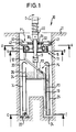
- FIG. 1 has a drilling device according to the invention 10 a pump device 11. This is on a drill string 13, which in the illustrated embodiment a Kelly boring bar is attached in one place, which within a drilled hole 20 in a ground 21 lies.
- a drilling tool 14 is also located on the drill string 13 attached below the pump device 11.
- the drilling tool 14 is as a cylindrical one Core drill pipe with roller bits 22 for removal of the ground.
- a fluid line 12 leads from the pump device 11 a channel 19 on the drilling tool 14 to the head side Roller chisels 22.
- By means of an arrow P2 directional fluid flow become the roller bits 22 washed around and freed from cuttings 24.
- Via one on the drilling tool 14 pipe 25 arranged parallel to the drill string 13 becomes the cuttings 24 according to the arrows P3 and P4 up into a container 26 on the drilling tool 14 promoted. From there, the cuttings 24 can be pulled out of the drilling tool 14 removed from the earth hole 20 will.
- the arrangement of the roller chisel 22 and the suction tube 24 on The scope of the drilling tool 14 can be the view according to FIG. 4 be removed.
- the pump device 11 As a rotor the pump device 11 is served by a hose 15 which is connected via a Carrier 16 attached to the drill string 13 in a rotationally fixed manner is.
- the hose 15 essentially surrounds the drill pipe 13 semi-circular at a constant distance.
- a Output 18 of the hose 15 is led down and communicates with the fluid line 12.
- the fluid can be air or Be rinsing liquid.
- a Pump stator 30 with two radially from a bearing device 31 outwardly extending stator arms 32 are provided. At the free end of the two stator arms 32 is in each case a roller 33 is arranged, which squeezes the elastic Hose 15 is present.
- the rollers 33 are parallel to Axles 34 arranged along the longitudinal axis of the drill string 13 are rotatable mounted on the stator arms 32.
- the pump stator 30 is on the drill string 13 via the bearing device 31 rotatable but axially fixed. over a torque arm 40 with four mutually perpendicular arranged brackets 41, which extend radially from the bearing sleeve 31 extend outwards, the pump stator 30 supported against a wall 27 of the earth bore 20 and against this rotatable.
- a torque arm 40 with four mutually perpendicular arranged brackets 41, which extend radially from the bearing sleeve 31 extend outwards, the pump stator 30 supported against a wall 27 of the earth bore 20 and against this rotatable.
- For axial displacement of the Torque support 40 and the pump stator 30 in the earth hole 20 according to the drilling progress are on the free Ends of the four holder 41 rolling elements 42 arranged around a horizontally directed axis 43 each rotatably mounted are.
- a respective Spring mechanism 44 mounted radially.
- the direction of rotation shown by arrows D is a fluid flow generated towards the drilling tool 14.
- the illustrated drilling device 10 in the Fluid line 12 can also be set a negative pressure, through which the cuttings 24 pass through the fluid line 12 is suctioned off in the direction of the pump device 11.
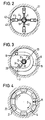
- Torque arm 140 explains that also for the drilling device described above can be used.
- the torque arm 140 comprises a base body 145 which with respect to one passed through a central opening 156 Drill string 113 is rotatably supported by bearings 119 is.
- the bearings 119 are axial and radial bearings, so that an axial displacement of the base body 145 relative to the Drill string 113 is prevented.
- the base body 145 is composed of two mutually parallel Plates 146, 147 built between which holder 141 with roller bodies 142 are attached.
- Distributed holders 161 have bearings for storing the rolling bodies 142 an axis 143 which is perpendicular to the longitudinal axis of the Drill string is 113 and in the direction of the rotational movement of drill string 113 has. So is the necessary power to Moving the torque arm 140 in the direction of displacement V low.
- the holders 141 are each pivotable via a bolt 148 mounted on the base body 145.
- the center of the Bolt axis of the respective bolt 148 is opposite one from the longitudinal axis of drill string 113 to the center of the Rolling element 142 extending radius beam 149 by an amount e offset against the direction of rotation D of drill string 113. Due to the constructive design the eccentricity e can be the magnitude of the contact and frictional forces be easily influenced.
- these are supported against one Support plate 151 on the base body 145 and press on the other hand against a radially inwardly extending lever arm 152 the respective holder 141.
- a certain spring preload the holder 141 guides the self-locking phase a.
- an adjusting device 153 is provided for setting the maximum swivel path of the holder 141 .
- This includes a stop 154 firmly connected to the base body 145 and the adjusting screws 155 located therein.
- the Torque support 140 in the direction of rotation D press the Lever arms 152 against the set screws 155 so that the Holder 141 with the rolling elements 142 in their radially protruding Location are fixed. If the direction of rotation is reversed the holder 141 against the pressure direction of the compression springs 150 released from their tense position.
- suitable Connection devices can be on the torque arm Cantilever arms are attached, which as a stator for Torque tap can serve against a rotor.
Abstract
Description
Die Erfindung betrifft eine Bohrvorrichtung zum Herstellen von Erdbohrungen gemäß dem Oberbegriff des Anspruchs 1. Die Erfindung betrifft weiter eine Drehmomentstütze für eine Bohrvorrichtung zum Abgreifen eines Drehmoments an einer von einem Bohrwerkzeug entfernten Stelle eines Bohrgestänges in einer Erdbohrung.The invention relates to a drilling device for manufacturing of earth bores according to the preamble of claim 1. Die The invention further relates to a torque arm for a Drilling device for tapping a torque on a location of a drill string distant from a drilling tool in an earth hole.
Bei der Herstellung von Bohrlöchern und Kernbohrungen, insbesondere mittels Rollenmeißel als Bohrwerkzeug, ist es notwendig, die zur Lösung des anstehenden Bodens eingesetzten Bohrwerkzeuge ständig vom Bohrklein zu reinigen, dieses von der Bohrlochsohle abzutransportieren und so einen optimalen Bohrfortschritt zu ermöglichen.In the production of boreholes and core bores, in particular using a roller chisel as a drilling tool, it is necessary to solve the soil in question To constantly clean drilling tools from the cuttings, this to be transported away from the bottom of the borehole and thus an optimal one Allow drilling progress.
Hierzu ist bekannt, den Bohrkopf mit den Bohrwerkzeugen entweder direkt mit Luft oder einer Spülflüssigkeit oder indirekt mittels Lufthebeverfahren oder im Saugbohrverfahren freizuspülen. Die Luft oder die Spülflüssigkeit werden dabei über einen Kanal entlang des Bohrstranges in einem Schlauch von der Arbeitsebene zur Bohrlochsohle geführt. Über einen Spülkopf am außenliegenden Drehantrieb wird die unterschiedliche Relativbewegung zwischen der stehenden Pumpe oder einem Kompressor und dem sich drehenden Bohrstrang im Bohrwerkzeug überwunden. For this purpose, it is known to use the drilling head with the drilling tools either directly with air or a flushing liquid or indirectly by means of air lifting or suction drilling rinse free. The air or the flushing liquid are in a channel along the drill string in a hose from the working level to the bottom of the borehole. Via a flushing head on the external rotary drive the different relative movement between the standing pump or a compressor and the rotating Drill string overcome in the drilling tool.
Diese bekannten Bohrvorrichtungen zum Herstellen von Erdbohrungen weisen also einen Bohrstrang, ein daran drehfest angebrachtes Bohrwerkzeug, einen Antrieb zum rotierenden Antreiben des Bohrstranges, eine Pumpeinrichtung und eine Fluidleitung auf, welche sich von der Pumpeinrichtung zu dem Bohrwerkzeug erstreckt, um mittels der Pumpeinrichtung am Bohrwerkzeug eine Fluidströmung zu erzeugen.These known drilling devices for making earth bores thus have a drill string, a non-rotatable attached drilling tool, a drive for rotating Driving the drill string, a pumping device and a fluid line, which extends from the pumping device extends to the drilling tool to by means of the pump device to generate a fluid flow on the drilling tool.
Bei einer solchen Bohrvorrichtung ist es nachteilig, daß das Spülmedium unter Druck über einen Spülkopf zum Bohrwerkzeug transportiert werden muß. Am Spülkopf können dabei Dichtigkeitsprobleme und ein entsprechender Druckverlust auftreten. Zudem ist bei Bohrvorrichtungen für intermittierende Bohrverfahren, wie dem Kellybohren, ein arbeitsintensiver Ein- und Ausbau der Spülleitungen bei jedem Bohrzyklus notwendig.With such a drilling device, it is disadvantageous that the flushing medium under pressure via a flushing head to the drilling tool must be transported. You can use the flushing head Tightness problems and a corresponding pressure loss occur. In addition, drilling equipment for intermittent Drilling processes, such as Kelly drilling, are labor intensive Installation and removal of the flushing lines with every drilling cycle necessary.
Der Erfindung liegt die Aufgabe zugrunde, eine Bohrvorrichtung zu schaffen, mit der ein einfaches und energiesparendes Entfernen von Bohrklein vom Bohrwerkzeug ermöglicht wird. Es ist eine weitere Aufgabe, für eine Bohrvorrichtung eine Drehmomentstütze anzugeben, durch die in einer Erdbohrung von einem Bohrstrang ein Drehmoment zum Antreiben eines Hilfsaggregats abgegriffen werden kann.The invention has for its object to provide a drilling device with which a simple and energy-saving removal of cuttings from the drilling tool is made possible. It is a further object to provide a torque support for a drilling device, by means of which a torque for driving an auxiliary unit can be tapped from a drill string in an earth borehole.
Der erste Teil der Aufgabe wird nach der Erfindung durch eine Bohrvorrichtung mit den kennzeichnenden Merkmalen des Anspruchs 1 gelöst.The first part of the task is accomplished according to the invention a drilling device with the characterizing features of Claim 1 solved.
Erfindungsgemäß ist vorgesehen,
- daß die Pumpeinrichtung einen Schlauch aufweist, der drehfest am Bohrstrang gehaltert ist und um diesen zumindest teilkreisförmig herum in einem konstanten Abstand angeordnet ist,
- daß ein Pumpenstator vorgesehen ist, der einerseits um den Bohrstrang drehbar gelagert und andererseits gegenüber einer Wandung der Erdbohrung drehfest abgestützt ist,
- daß der Pumpenstator einen sich radial zum Bohrstrang erstreckenden Statorarm aufweist, der zwischen dem Bohrstrang und dem Schlauch angeordnet ist, und
- daß der Statorarm bereichsweise am Schlauch quetschend anliegt, wobei der Statorarm bei mit dem Bohrstrang rotierendem Schlauch diesen überstreicht.
- that the pump device has a hose which is held in a rotationally fixed manner on the drill string and is arranged at a constant distance around it at least in part-circle fashion,
- that a pump stator is provided which, on the one hand, is rotatably supported about the drill string and, on the other hand, is rotatably supported with respect to a wall of the earth borehole,
- that the pump stator has a radially extending to the drill string stator arm which is arranged between the drill string and the hose, and
- that the stator arm rests in a squeezing manner on the tube, the stator arm sweeping over the tube when the tube is rotating.
Nach einem Grundgedanken der Erfindung wird eine einfache Schlauchpumpe hinter dem Bohrwerkzeug im Bohrloch installiert. Die Pumpe wird dabei durch die Drehung des Bohrstranges, beispielsweise einer Kellystange, angetrieben. Die Pumpeinrichtung weist einen Schlauch auf, der am Bohrstrang über eine geeignete Haltevorrichtung drehfest angebracht ist. Der Schlauch rotiert so mit dem Bohrstrang und bildet einen Rotor der Pumpeinrichtung. Bei Rotation des Bohrstranges läuft der Schlauch an quetschend anliegenden Statorarmen des Stators vorbei, welcher drehfest an der Bohrlochwandung abgestützt ist. Durch die Relativbewegung zwischen dem Stator und dem Rotor beim Bohren wird eine Pumpwirkung erzeugt. Je nach Drehrichtung kann so ein Druck zum Freispülen des Bohrwerkzeugs oder ein Sog zum Absaugen des Bohrkleins eingestellt werden.According to a basic idea of the invention, a simple one Peristaltic pump installed behind the drilling tool in the borehole. The pump is activated by the rotation of the drill string, for example a Kelly rod. The pump device has a hose which is on the drill string attached non-rotatably via a suitable holding device is. The hose rotates with the drill string and forms a rotor of the pump device. With rotation of the drill string, the hose runs to squeezing Stator arms of the stator over, which rotatably on the borehole wall is supported. Through the relative movement between the stator and the rotor when drilling creates a pumping action. Depending on the direction of rotation, a Pressure to flush the drilling tool or suction to Suction off the cuttings can be set.
Während ein Schlauchende mit einer zum Bohrwerkzeug führenden Fluidleitung verbunden ist, steht das andere Schlauchende mit einem Fluidreservoir in Verbindung, welches bei einer einfachen Ausführung umgebende Luft oder Spülflüssigkeit sein kann. Das Schlauchende kann auch mit einem außerhalb des Bohrlochs angeordneten Behälters in Leitungsverbindung stehen. In jedem Fall entfällt bei der erfindungsgemäßen Bohrvorrichtung eine Energieübertragung von einem zusätzlichen feststehenden Energieerzeuger auf das rotierende Bohrwerkzeug.While one hose end with one leading to the drilling tool The other hose end is connected to the fluid line in connection with a fluid reservoir, which at a simple version of surrounding air or flushing liquid can be. The hose end can also be used with an outside the well arranged container in line connection stand. In any case, the invention does not apply Drill an energy transfer from one additional fixed energy generator on the rotating Drilling tool.
Eine bevorzugte Ausführungsform der Erfindung besteht darin, daß der Pumpenstator axial fest auf dem Bohrstrang gelagert ist. Der Pumpenstator kann so beim Bohrfortschritt dem Schlauch folgen.A preferred embodiment of the invention consists in that the pump stator is axially fixed on the drill string is. The pump stator can thus as the drilling progresses follow the hose.
Für eine besonders einfache Handhabung der Pumpeinrichtung ist vorgesehen, daß der Pumpenstator eine Drehmomentstütze aufweist, welche an der Wandung der Erdbohrung in Rotationsrichtung beim Bohren fest und in Längsrichtung des Bohrstrangs schiebbar anliegt. Der Pumpenstator kann so besonders einfach auf dem Bohrstrang montiert und entsprechend dem Bohrfortschritt mit dem Bohrstrang nachgeführt werden.For particularly easy handling of the pump device it is provided that the pump stator is a torque arm has, which on the wall of the earth hole in the direction of rotation when drilling firmly and in the longitudinal direction of the The drill string is sliding. The pump stator can be so special simply mounted on the drill string and accordingly track the drilling progress with the drill string will.
Im Hinblick auf eine ausreichende Dimensionierung und Leistung der Pumpeinrichtung ist es bei einer weiteren Ausführungsform der erfindungsgemäßen Bohrvorrichtung bevorzugt, daß das Bohrwerkzeug ein Kernbohrrohr mit einem Kanal aufweist und daß der Schlauch und der Kanal zum Bilden der Fluidleitung verbunden sind.With regard to sufficient dimensioning and The power of the pumping device is another Preferred embodiment of the drilling device according to the invention, that the drilling tool is a core drill pipe with a Has channel and that the hose and the channel to Form the fluid line are connected.
Ein besonders guter Bohrfortschritt beim Bohren wird dadurch gewährleistet, daß am Bohrwerkzeug ein Behälter zur Aufnahme von Spülflüssigkeit und Bohrklein angeordnet ist und daß ein Rohr zwischen dem Behälter und einer Bodenabtragseinrichtung am Bohrwerkzeug vorgesehen ist. Durch dieses Rohr kann beispielsweise angefallendes Bohrklein in den Behälter abgesaugt werden, welcher beim Entfernen des Bohrwerkzeugs aus dem erstellten Bohrloch entleert werden kann. Der Behälter kann aber auch als Spülflüssigkeitsreservoir verwendet werden. This makes particularly good drilling progress ensures that a container for Recording of rinsing liquid and cuttings is arranged and that a pipe between the container and a soil removal device is provided on the drilling tool. By this pipe can, for example, accumulate cuttings be sucked into the container, which when removing the Drilling tools are emptied from the drilled hole can. The container can also be used as a rinsing liquid reservoir be used.
Eine weitere bevorzugte Ausführungsform der Erfindung besteht darin, daß der Statorarm an seinem den Schlauch quetschenden freien Ende eine Rolle aufweist, die um eine zur Längsrichtung des Bohrstranges parallele Rollenachse drehbar gelagert ist. Durch die Rolle wird Verschleiß am Schlauch aufgrund der Relativbewegung gegenüber dem Statorarm weitgehend vermieden.Another preferred embodiment of the invention exists in that the stator arm squeezing the hose on its free end has a role around one to Longitudinal direction of the drill string parallel roller axis rotatable is stored. The role is wear on Hose due to the relative movement in relation to the stator arm largely avoided.
Für eine gleichmäßige Druckerzeugung ist es vorgesehen, daß der Pumpenstator mehrere gleichmäßig über seinen Umfang verteilte Statorarme aufweist. Insbesondere sind zwei, im 180o-Winkel zueinander angeordnete Statorarme vorgesehen.For uniform pressure generation, it is provided that the pump stator has several stator arms distributed uniformly over its circumference. In particular two, in each 180 o angle arranged stator arms are provided.
Bei einer anderen erfindungsgemäßen Ausführungsform ist es vorteilhaft, daß mehrere Pumpeinrichtungen am Bohrstrang angeordnet sind. Hierbei sind mehrere Schläuche und mehrere Statorarme in Achsrichtung hintereinander angeordnet. Durch mehrere Pumpeinrichtungen kann selbst eine relativ hohe Pumpkapazität eingestellt werden. Hierzu können auch mehrere Schläuche auf einen gemeinsamen Träger als Rotor übereinandergelegt werden.In another embodiment of the invention it is advantageous that several pumping devices on the drill string are arranged. Here are several hoses and several Stator arms arranged one behind the other in the axial direction. By multiple pumping devices can even be a relatively high one Pump capacity can be set. Several can do this Hoses placed on top of one another on a common carrier as a rotor will.
Der zweite Teil der Aufgabe wird gelöst durch eine Drehmomentstütze für eine Bohrvorrichtung zum Abgreifen eines Drehmoments an einer von einem Bohrwerkzeug entfernten Stelle eines Bohrstranges in einer Erdbohrung, mit
- einem Grundkörper, der eine mittig angeordnete Öffnung zum Durchführen des Bohrstranges aufweist,
- einer Lagereinrichtung an der Öffnung zum drehbaren Lagern des Grundkörpers am Bohrstrang,
- mindestens drei voneinander beabstandet am Grundkörper angeordneten Haltern, die sich radial zur Längsachse des durch die Öffnung hindurchzuführenden Bohrstranges vom Grundkörper weg erstrecken,
- mindestens einem Wälzkörper an jedem Halter, an dem der Wälzkörper um eine Achse drehbar gelagert ist, die jeweils senkrecht zur Längsachse des durch die Öffnung durchzuführenden Bohrstranges und tangential zu dessen Rotationsrichtung an den Haltern angeordnet sind, und
- einer Druckeinrichtung zum Erzeugen einer Druckkraft, welche die Halter mit den Wälzkörpern im wesentlichen radial nach außen vom Grundkörper weg drückt.
- a base body which has a centrally arranged opening for the passage of the drill string,
- a bearing device at the opening for rotatably supporting the base body on the drill string,
- at least three spaced apart holders on the base body, which extend radially to the longitudinal axis of the drill string to be passed through the opening away from the base body,
- at least one rolling element on each holder, on which the rolling element is rotatably mounted about an axis, which are arranged perpendicular to the longitudinal axis of the drill string to be passed through the opening and tangential to the direction of rotation thereof on the holders, and
- a pressure device for generating a compressive force which presses the holder with the rolling elements essentially radially outward away from the base body.
Durch die erfindungsgemäße Drehmomentstütze kann eine Aufteilung des Drehmoments eines Bohrstanges in der Nähe der Wirkstelle bei der Herstellung von Erdbohrungen durchgeführt werden. Durch die am Bohrstrang angeordnete, aber relativ dazu ruhende Drehmomentstütze läßt sich eine mechanische Leistung abgreifen, die für gegebenenfalls erforderliche Sekundärantriebe oder Hilfsaggregate genutzt werden kann. Ein derartiges Hilfsaggregat kann insbesondere eine Pumpe sein, welche zum Abtransport von Bohrklein von der Bohrlochsohle dient. Die Antriebsleistung der Bohrvorrichtung oder des Kraftdrehkopfes ist im allgemeinen größer als die für den Bohrprozeß benötigte Leistung. Daher ist es ohne Veränderungen am Gerät möglich, den für den Sekundärantrieb benötigten Teil dieser Leistung über den Bohrstrang selbst zur Wirkstelle zu befördern.The torque arm according to the invention allows a division of the torque of a drill rod near the Point of action carried out in the production of earth bores will. By arranged on the drill string, however a torque arm resting relative to it can be a tap mechanical performance for any required Secondary drives or auxiliary units used can be. Such an auxiliary unit can in particular be a pump which is used to remove cuttings from the bottom of the borehole. The drive power of the drilling device or the turret in general greater than the power required for the drilling process. Therefore it is possible without changes to the device, for the Secondary drive required part of this power over the To transport the drill string to the active site.
Gegenüber herkömmlichen Vorrichtungen, bei denen eine benötigte Antriebsleistung in Form elektrischer, pneumatischer oder hydraulischer Energie von einer Stelle außerhalb des Bohrlochs einem Hilfsaggregat zugeführt wird, bietet die erfindungsgemäße Drehmomentstütze deutliche Vorteile. So entfällt die aufwendige Form der Übertragung von Energie von einem feststehenden Energieerzeuger auf das rotierende Werkzeug. Da weiter die erfindungsgemäße Drehmomentstütze im Bohrloch hinter dem Bohrwerkzeug angeordnet werden kann, entfällt das Problem einer Längenanpassung der Energieleitung bei Bohrfortschritt, insbesondere wenn beim Bohren Kellystangen verwendet werden.Compared to conventional devices where one is needed Drive power in the form of electrical, pneumatic or hydraulic energy from somewhere outside the borehole is supplied to an auxiliary unit the torque arm according to the invention has clear advantages. This eliminates the complex form of energy transmission from a fixed energy generator to the rotating one Tool. Since further the torque arm according to the invention can be placed in the borehole behind the drilling tool, the problem of adjusting the length of the power line is eliminated when drilling progress, especially when drilling Kelly rods can be used.
Für eine Anpassung an verschiedene Bohrdurchmesser ist erfindungsgemäß vorgesehen, daß die Halter gegenüber dem Grundkörper verschiebbar sind.For an adaptation to different drilling diameters is according to the invention provided that the holder opposite the Basic bodies are displaceable.
Eine automatische Anpassung an Durchmesserschwankungen wird bei einer Ausführungsform der Erfindung dadurch erreicht, daß die Druckeinrichtung einen Federmechanismus aufweist, der die Halter mit den Wälzkörpern mit einer definierten Druckkraft gegen die Wandung der Erdbohrung drückt. Die erfindungsgemäße Drehmomentstütze wird so durch Federkraft ständig in Kontakt mit der verrohrten oder unverrohrten Wandung der Erdbohrung gehalten. Durch den radialen Zustellhub der Wälzkörper können Durchmesserunterschiede, beispielsweise beim Übergang vom Bohrrohr zur auslaufenden Bohrung ausgeglichen werden.An automatic adjustment to fluctuations in diameter will achieved in one embodiment of the invention that the pressure device has a spring mechanism, which the holder with the rolling elements with a defined Compressive force against the wall of the borehole. The invention Torque arm is so by spring force constantly in contact with the cased or uncased Wall of the borehole held. Thanks to the radial feed stroke the rolling elements can differ in diameter, for example at the transition from the drill pipe to the outgoing one Hole to be compensated.
Ein bevorzugtes Ausschwenken der Halter wird dadurch erreicht, daß die Halter jeweils am Grundkörper um einen Bolzen schwenkbar gelagert sind, der parallel zur Längsachse des Bohrstranges gerichtet ist.A preferred pivoting out of the holder is achieved that the holder on the base body around a bolt are pivotally mounted, parallel to the longitudinal axis of the drill string is directed.
Diese Ausführungsform ist in bevorzugter Weise dadurch weitergebildet, daß jeder Halter einen radial nach innen ragenden Hebelarm aufweist und daß zwischen dem Hebelarm und dem Grundkörper eine Druckfeder angeordnet ist, welche den Halter in seine radial außenliegende Position drückt. Die Drehmomentübertragung erfolgt dabei erfindungsgemäß nach dem Prinzip der Selbsthemmung durch Reibung in Umfangsrichtung. Sie unterscheidet sich dabei von dem als "Freilauf" bekannten Maschinenelement dadurch, daß in axialer Richtung durch die Verwendung von Wälzkörpern keine Selbsthemmung einsetzt. Die Druckkraft der Druckfeder ist eingestellt, um die Reibkräfte der Drehmomentstütze in Vorschubrichtung möglichst gering zu halten. Beispielsweise beim Bohren mit Kellybohrstangen wird so die oszillierende Bewegung beim Bohren kaum beeinträchtigt.This embodiment is preferred further developed that each holder a radially inward projecting lever arm and that between the lever arm and a compression spring is arranged on the base body, which the holder in its radially outer position presses. The torque transmission takes place according to the invention according to the principle of self-locking through friction in the circumferential direction. It differs from that known as a "freewheel" machine element in that in axial direction through the use of rolling elements none Self-locking starts. The pressure force of the compression spring is set the friction forces of the torque arm in the feed direction to keep as low as possible. For example when drilling with Kelly boring bars it becomes the oscillating one Movement when drilling hardly affected.
Bei einer weiteren erfindungsgemäßen Ausführungsform ist vorgesehen, daß ein Anschlag für jeden Halter am Grundkörper vorgesehen ist, an den der Halter beim Bohren anliegt. Der Anschlag fixiert so die Halter in ihrer Lage. Bei Drehrichtungsumkehr des Bohrstrangs wird ein am Anschlag anliegender Hebelarm des Halters vom Anschlag weggedreht, so daß die Selbsthemmung des Mechanismus gelöst wird. Hierdurch wird einerseits ein Antrieb, beispielsweise einer Pumpe, nur in einer zulässigen Drehrichtung sichergestellt. Außerdem kann bei dieser Ausführungsform vor der Aufwärtsbewegung durch kurzfristiges Zurückdrehen des Bohrstranges die Drehmomentstütze nicht aus der Verspannung gelöst werden.In a further embodiment according to the invention provided that a stop for each holder on the base body is provided, against which the holder rests during drilling. The stop thus fixes the holder in its position. When reversing the direction of rotation the drill string becomes one that is in contact with the stop Lever arm of the holder turned away from the stop, see above that the self-locking of the mechanism is released. Hereby becomes a drive, for example one Pump, only ensured in an admissible direction of rotation. In addition, in this embodiment, before the upward movement by briefly turning back the drill string the torque arm cannot be released from the tension.
Zur Einstellung des maximal zulässigen Durchmessers, auf den die Wälzkörper ausschwenken können, ist eine erfindungsgemäße Drehmomentstütze dadurch weitergebildet, daß eine Justiereinrichtung an jedem Anschlag vorgesehen ist, mit der die Auslenkung des jeweiligen Halters beim Bohren einstellbar ist.For setting the maximum permissible diameter, on which the rolling elements can swing out is one according to the invention Torque arm further developed in that an adjustment device is provided on each stop, with which the deflection of the respective holder during drilling is adjustable.
Die Erfindung wird weiter anhand von bevorzugten Ausführungsbeispielen erläutert, welche schematisch in den Zeichnungen dargestellt sind. In den Zeichnungen zeigen:
- Fig. 1
- eine Querschnittsansicht einer erfindungsgemäßen Bohrvorrichtung in einer Erdbohrung;
- Fig. 2
- eine Schnittdarstellung gemäß dem Schnitt A-A in Figur 1;
- Fig. 3
- eine Schnittdarstellung gemäß dem Schnitt B-B in Figur 1;
- Fig. 4
- eine Schnittdarstellung gemäß dem Schnitt C-C in Figur 1;
- Fig. 5
- eine teilweise geschnittene Draufsicht auf eine erfindungsgemäße Drehmomentstütze in einer Erdbohrung;
- Fig. 6
- eine Schnittdarstellung gemäß dem Schnitt A-A in Figur 5; und
- Fig. 7
- eine Schnittdarstellung gemäß dem Schnitt B-B in Fig. 5.
- Fig. 1
- a cross-sectional view of a drilling device according to the invention in an earth hole;
- Fig. 2
- a sectional view along section AA in Figure 1;
- Fig. 3
- a sectional view according to the section BB in Figure 1;
- Fig. 4
- a sectional view according to the section CC in Figure 1;
- Fig. 5
- a partially sectioned plan view of a torque arm according to the invention in an earth hole;
- Fig. 6
- a sectional view along the section AA in Figure 5; and
- Fig. 7
- 5 shows a sectional view according to the section BB in FIG. 5.
Gemäß Figur 1 weist eine erfindungsgemäße Bohrvorrichtung
10 eine Pumpeinrichtung 11 auf. Diese ist an einem Bohrstrang
13, welcher bei der dargestellten Ausführungsform
eine Kellybohrstange ist, an einer Stelle angebracht, welche
innerhalb einer erstellten Erdbohrung 20 in einem Boden
21 liegt. Am Bohrstrang 13 ist weiter ein Bohrwerkzeug 14
unterhalb der Pumpeinrichtung 11 angebracht. Bei der dargestellten
Ausführungsform ist das Bohrwerkzeug 14 als ein zylinderförmiges
Kernbohrrohr mit Rollenmeißeln 22 zum Abtragen
des Bodens ausgebildet.According to Figure 1 has a drilling device according to the invention
10 a pump device 11. This is on a
Eine Fluidleitung 12 führt von der Pumpeinrichtung 11 über
einen Kanal 19 am Bohrwerkzeug 14 zu den kopfseitig angeordneten
Rollenmeißeln 22. Durch eine gemäß dem Pfeil P2
gerichtete Fluidströmung werden die Rollenmeißeln 22
umspült und von Bohrklein 24 befreit. Über ein am Bohrwerkzeug
14 parallel zum Bohrstrang 13 angeordnetes Rohr 25
wird das Bohrklein 24 entsprechend den Pfeilen P3 und P4
nach oben in einen Behälter 26 auf dem Bohrwerkzeug 14
gefördert. Von dort kann das Bohrklein 24 beim Herausziehen
des Bohrwerkzeugs 14 aus der Erdbohrung 20 entfernt
werden.A
Die Anordnung der Rollenmeißel 22 und des Saugrohres 24 am
Umfang des Bohrwerkzeugs 14 kann der Ansicht gemäß Figur 4
entnommen werden.The arrangement of the
Der Aufbau und die Funktion der Pumpeinrichtung 11 wird
weiter anhand der Figuren 1, 2 und 3 erläutert. Als Rotor
der Pumpeinrichtung 11 dient ein Schlauch 15, der über einen
Träger 16 an dem Bohrgestänge 13 drehfest angebracht
ist. Der Schlauch 15 umgibt das Bohrgestänge 13 im wesentlichen
teilkreisförmig in einem konstanten Abstand. Ein
Ausgang 18 des Schlauchs 15 ist nach unten geführt und
steht mit der Fluidleitung 12 in Verbindung. Hingegen ist
ein Eingang 17 des Schlauches 15 nach oben in Richtung aus
dem Bohrloch gerichtet, um ein Fluid in Richtung des Pfeiles
P1 aufzunehmen. Das Fluid kann dabei Luft oder eine
Spülflüssigkeit sein.The structure and function of the pump device 11 will
further explained with reference to Figures 1, 2 and 3. As a rotor
the pump device 11 is served by a
Zur Erzeugung einer Strömung in dem Schlauch 15 ist ein
Pumpenstator 30 mit zwei sich radial von einer Lagereinrichtung
31 nach außen erstreckenden Statorarmen 32 vorgesehen.
Am freien Ende der beiden Statorarme 32 ist jeweils
eine Rolle 33 angeordnet, die quetschend an dem elastischen
Schlauch 15 anliegt. Die Rollen 33 sind über parallel zur
Längsachse des Bohrstrangs 13 angeordnete Achsen 34 drehbar
an den Statorarmen 32 gelagert. To generate a flow in the
Der Pumpenstator 30 ist auf dem Bohrstrang 13 über die Lagereinrichtung
31 drehbar aber axial fest gelagert. Über
eine Drehmomentstütze 40 mit vier rechtwinklig zueinander
angeordneten Halterungen 41, welche sich radial von der Lagerhülse
31 nach außen erstrecken, ist der Pumpenstator 30
gegenüber einer Wandung 27 der Erdbohrung 20 abgestützt und
gegenüber dieser drehfest. Zum axialen Verschieben der
Drehmomentstütze 40 und des Pumpenstators 30 in der Erdbohrung
20 entsprechend dem Bohrfortschritt sind an den freien
Enden der vier Halter 41 Wälzkörper 42 angeordnet, die um
eine horizontal gerichtete Achse 43 jeweils drehbar gelagert
sind. Weiter sind zum Ausgleich von Durchmesserschwankungen
der Erdbohrung 20 die Halter 41 über einen jeweiligen
Federmechanismus 44 radial verschiebbar gelagert.The pump stator 30 is on the
Zwischen dem so abgestützten Pumpenstator 30 und dem mit
dem Bohrstrang 13 rotierenden Schlauch 15 als Pumpenrotor
stellt sich eine Relativbewegung ein. Bei dieser überstreichen
die Rollen 33 an den Statorarmen 32 den Schlauch 15
quetschend und drücken so sich im Schlauch befindliches
Fluid in Richtung des Ausgangs 18 in die Fluidleitung 12.
Dabei wird erfindungsgemäß bei relativ langsamer Umdrehung
ein ausreichender Fluiddruck erreicht, um das Bohrwerkzeug
14 von anfallendem Bohrklein 24 freizuspülen. Eine zusätzliche
Energieübertragung zur Fluiddruckeinstellung
ist nicht notwendig. Zur Erhöhung der Pumpkapazität können
gegebenenfalls weitere Pumpeinrichtungen 11 hintereinander
am Bohrstrang 13 vorgesehen werden. Hierfür ist eine entsprechend
ausgebildete Verbindung 45 am Bohrstrang 13 zu
lösen, wobei zusätzliche Pumpeinrichtungen 11 in einfacher
Weise auf den Bohrstrang 13 aufgebracht werden können.Between the pump stator 30 supported in this way and the
the
Bei der dargestellten Ausführungsform mit der entsprechend
den Pfeilen D gezeigten Drehrichtung wird eine Fluidströmung
zum Bohrwerkzeug 14 hin erzeugt. Bei Drehrichtungsumkehr
kann mit der dargestellten Bohrvorrichtung 10 in der
Fluidleitung 12 auch ein Unterdruck eingestellt werden,
durch den das Bohrklein 24 durch die Fluidleitung 12 nach
oben in Richtung der Pumpeinrichtung 11 abgesaugt wird.In the illustrated embodiment with the corresponding
The direction of rotation shown by arrows D is a fluid flow
generated towards the
Im Zusammenhang mit den Figuren 5 bis 7 wird eine erfindungsgemäße
Drehmomentstütze 140 erläutert, die auch für
die vorstehend beschriebene Bohrvorrichtung einsetzbar ist.
Die Drehmomentstütze 140 umfaßt einen Grundkörper 145, der
bezüglich eines durch eine mittige Öffnung 156 durchgegeführten
Bohrstrangs 113 mittels Lagern 119 drehbar gelagert
ist. Die Lager 119 sind Axial- und Radiallager, so daß
eine axiale Verschiebung des Grundkörpers 145 gegenüber dem
Bohrstrang 113 verhindert wird.In connection with Figures 5 to 7 is an
Der Grundkörper 145 ist aus zwei zueinander parallel angeordneten
Platten 146, 147 aufgebaut, zwischen denen Halter
141 mit Wälzkörpern 142 angebracht sind.The
Alle drei gleichmäßig über den Umfang des Grundkörpers 145
verteilten Halter 161 weisen zur Lagerung der Wälzkörper 142
eine Achse 143 auf, welche senkrecht zur Längsachse des
Bohrstrangs 113 ist und in Richtung der Rotationsbewegung
des Bohrstrangs 113 weist. So ist die notwendige Kraft zum
Verschieben der Drehmomentstütze 140 in Verschubrichtung V
gering.All three evenly over the circumference of the
Die Halter 141 sind jeweils über einen Bolzen 148 schwenkbar
am Grundkörper 145 gelagert. Der Mittelpunkt der
Bolzenachse der jeweiligen Bolzen 148 ist gegenüber einem
von der Längsachse des Bohrstrangs 113 zum Mittelpunkt der
Wälzkörper 142 verlaufenden Radiusstrahl 149 um einen Betrag
e versetzt, und zwar entgegen der Rotationsrichtung
D des Bohrstrangs 113. Durch die konstruktive Gestaltung
der Exzentrizität e kann die Größe der Anpreß- und Reibungskräfte
leicht beeinflußt werden. The
Um beim Eintritt in eine Erdbohrung 20 im Boden 21 den Kontakt
der Wälzkörper 142 mit einer Wandung 27, welche bei
der dargestellten Ausführungsform ein Bohrrohr ist, herzustellen,
ist eine Druckeinrichtung 144 mit Druckfedern 150
vorgesehen. Diese stützen sich einerseits gegenüber einer
Stützplatte 151 am Grundkörper 145 ab und drücken andererseits
gegen einen radial nach innen ragenden Hebelarm 152
der jeweiligen Halter 141. Eine gewisse Federvorspannung
der Halter 141 leitet dabei die Phase der Selbsthemmung
ein.To make contact when entering an earth hole 20 in the bottom 21
the rolling
Zur Einstellung des maximalen Schwenkwegs der Halter 141
ist eine Justiereinrichtung 153 vorgesehen. Diese umfaßt
einen fest mit dem Grundkörper 145 verbundenen Anschlag 154
und darin befindliche Stellschrauben 155. Bei Drehung der
Drehmomentstütze 140 in Rotationsrichtung D drücken die
Hebelarme 152 gegen die Stellschrauben 155, so daß die
Halter 141 mit den Wälzkörpern 142 in ihrer radial vorstehenden
Lage fixiert sind. Bei Drehrichtungsumkehr werden
die Halter 141 entgegen der Druckrichtung der Druckfedern
150 aus ihrer verspannten Lage gelöst. Über geeignete
Verbindungseinrichtungen können an der Drehmomentstütze
Kragarme angebracht werden, welche als Stator zum
Drehmomentabgriff gegenüber einem Rotor dienen können.For setting the maximum swivel path of the
Claims (15)
dadurch gekennzeichnet,
characterized by
dadurch gekennzeichnet,
characterized by
dadurch gekennzeichnet,
characterized by
dadurch gekennzeichnet,
characterized by
dadurch gekennzeichnet,
characterized by
dadurch gekennzeichnet,
characterized by
dadurch gekennzeichnet,
characterized by
dadurch gekennzeichnet,
characterized by
zum Abgreifen eines Drehmoments an einer von einem Bohrwerkzeug entfernten Stelle eines Bohrstranges in einer Erdbohrung, mit
for tapping off a torque at a location of a drill string in an earth hole remote from a drilling tool, with
dadurch gekennzeichnet,
characterized by
dadurch gekennzeichnet,
characterized by
dadurch gekennzeichnet,
characterized by
dadurch gekennzeichnet,
characterized by
dadurch gekennzeichnet,
characterized by
dadurch gekennzeichnet,
characterized by
Applications Claiming Priority (2)
| Application Number | Priority Date | Filing Date | Title |
|---|---|---|---|
| DE19702533 | 1997-01-24 | ||
| DE19702533A DE19702533A1 (en) | 1997-01-24 | 1997-01-24 | Drilling device and torque arm for a drilling device |
Publications (2)
| Publication Number | Publication Date |
|---|---|
| EP0855490A2 true EP0855490A2 (en) | 1998-07-29 |
| EP0855490A3 EP0855490A3 (en) | 2000-03-29 |
Family
ID=7818266
Family Applications (1)
| Application Number | Title | Priority Date | Filing Date |
|---|---|---|---|
| EP98101099A Withdrawn EP0855490A3 (en) | 1997-01-24 | 1998-01-22 | Drilling apparatus and downhole torque generator |
Country Status (6)
| Country | Link |
|---|---|
| EP (1) | EP0855490A3 (en) |
| JP (1) | JPH10231675A (en) |
| KR (1) | KR19980070790A (en) |
| CN (1) | CN1198502A (en) |
| DE (1) | DE19702533A1 (en) |
| SG (1) | SG71749A1 (en) |
Cited By (3)
| Publication number | Priority date | Publication date | Assignee | Title |
|---|---|---|---|---|
| EP2113632A1 (en) | 2008-04-28 | 2009-11-04 | BAUER Maschinen GmbH | Attachment device for forming a fluid supply |
| CN101525978B (en) * | 2009-02-18 | 2012-02-01 | 陈月辉 | Automatic hydraulic drilling mechanism |
| WO2017167856A1 (en) * | 2016-04-01 | 2017-10-05 | Nk Trading And Engineering Gmbh | Drilling method and shaft drilling system |
Families Citing this family (7)
| Publication number | Priority date | Publication date | Assignee | Title |
|---|---|---|---|---|
| DE10310726B3 (en) * | 2003-03-12 | 2004-09-30 | Bauer Spezialtiefbau Gmbh | Core drilling arrangement with flushing has container for bore flushing with core material released from tube arranged in upper region of core drilling tube into which pump feeds, overflow openings |
| JP3968054B2 (en) * | 2003-06-02 | 2007-08-29 | 日立ビアメカニクス株式会社 | Printed circuit board processing machine |
| DE10328609B3 (en) * | 2003-06-25 | 2004-12-02 | Bauer Maschinen Gmbh | Wet-drilling tool for drilling a hole in the ground comprises a passage device having a tubular dome with an inlet opening above a collecting container and a connecting rod connection for a boring rod |
| JP5273568B2 (en) * | 2010-05-20 | 2013-08-28 | 独立行政法人日本原子力研究開発機構 | In-hole excitation source |
| WO2013034998A2 (en) * | 2011-09-06 | 2013-03-14 | Petrus Christiaan Gouws | Auxiliary equipment for use with drilling apparatus |
| JP7112813B2 (en) * | 2018-05-21 | 2022-08-04 | Jfeシビル株式会社 | Surplus soil removal device and surplus soil removal system |
| CN112196463B (en) * | 2020-09-30 | 2022-10-04 | 中油国家油气钻井装备工程技术研究中心有限公司 | Quick moving drilling pump set dragging and prying device |
Citations (2)
| Publication number | Priority date | Publication date | Assignee | Title |
|---|---|---|---|---|
| US3841420A (en) * | 1972-03-24 | 1974-10-15 | M Russell | Directional drilling means |
| EP0308083A2 (en) * | 1987-09-04 | 1989-03-22 | Frank Manchak, Jr. | Device for sampling soils and retaining volatiles therein and method of using same |
-
1997
- 1997-01-24 DE DE19702533A patent/DE19702533A1/en not_active Withdrawn
-
1998
- 1998-01-22 EP EP98101099A patent/EP0855490A3/en not_active Withdrawn
- 1998-01-23 SG SG1998000164A patent/SG71749A1/en unknown
- 1998-01-23 KR KR1019980002106A patent/KR19980070790A/en not_active Application Discontinuation
- 1998-01-24 CN CN98105981A patent/CN1198502A/en active Pending
- 1998-01-26 JP JP10012710A patent/JPH10231675A/en active Pending
Patent Citations (2)
| Publication number | Priority date | Publication date | Assignee | Title |
|---|---|---|---|---|
| US3841420A (en) * | 1972-03-24 | 1974-10-15 | M Russell | Directional drilling means |
| EP0308083A2 (en) * | 1987-09-04 | 1989-03-22 | Frank Manchak, Jr. | Device for sampling soils and retaining volatiles therein and method of using same |
Cited By (7)
| Publication number | Priority date | Publication date | Assignee | Title |
|---|---|---|---|---|
| EP2113632A1 (en) | 2008-04-28 | 2009-11-04 | BAUER Maschinen GmbH | Attachment device for forming a fluid supply |
| AU2009201456B2 (en) * | 2008-04-28 | 2010-09-23 | Bauer Maschinen Gmbh | Connection device for forming a fluid supply |
| US8002051B2 (en) | 2008-04-28 | 2011-08-23 | Bauer Maschinen Gmbh | Connection device for forming a fluid supply |
| KR101067726B1 (en) * | 2008-04-28 | 2011-09-28 | 바우어 머쉬넨 게엠베하 | Connection device for forming a fluid supply |
| CN101525978B (en) * | 2009-02-18 | 2012-02-01 | 陈月辉 | Automatic hydraulic drilling mechanism |
| WO2017167856A1 (en) * | 2016-04-01 | 2017-10-05 | Nk Trading And Engineering Gmbh | Drilling method and shaft drilling system |
| AU2017242643B2 (en) * | 2016-04-01 | 2020-01-23 | Nk Trading And Engineering Gmbh | Drilling method and shaft drilling system |
Also Published As
| Publication number | Publication date |
|---|---|
| JPH10231675A (en) | 1998-09-02 |
| DE19702533A1 (en) | 1998-07-30 |
| CN1198502A (en) | 1998-11-11 |
| EP0855490A3 (en) | 2000-03-29 |
| KR19980070790A (en) | 1998-10-26 |
| SG71749A1 (en) | 2000-04-18 |
Similar Documents
| Publication | Publication Date | Title |
|---|---|---|
| EP1679462B1 (en) | Pipe laying apparatus | |
| EP0855490A2 (en) | Drilling apparatus and downhole torque generator | |
| EP0190669B1 (en) | Drilling apparatus | |
| DE2654197A1 (en) | FLUID MOTOR ARRANGEMENT | |
| EP2728104A1 (en) | Method for producing a horizontally drilled bore hole in the ground and horizontal drilling device | |
| EP2553202B1 (en) | Method for operating a horizontal drilling device and horizontal drilling device | |
| EP0928876B1 (en) | Device for drilling a bore hole in the ground | |
| WO1997034070A9 (en) | Device for drilling a bore hole in the ground | |
| DE10023467C1 (en) | Boring device, to form bores using borer tubes, has holder unit with rotation plate for borer tube having radial locking opening and has locking unit on plate with locking bolt to lock borer tube | |
| DE10227204B4 (en) | Method for cleaning pipelines and pipe cleaning machine therefor | |
| EP3299572B1 (en) | Method and drilling assembly for cased drilling | |
| EP2553203B1 (en) | Horizontal drilling device | |
| EP0887126B1 (en) | Pipe expanding device | |
| WO2022028955A1 (en) | Device for cleaning a spiral space of an auger and method for producing a drilled hole | |
| EP1649128B1 (en) | Device for drilling a bore in the ground | |
| DE3011449C2 (en) | Device for making an upwardly directed borehole | |
| EP0545922A1 (en) | Drilling machine table. | |
| EP1012440B1 (en) | Boring device | |
| EP1662087B1 (en) | Device and method for providing hydraulic energy | |
| DE10218174B4 (en) | Earth boring device with automatic thread equalization 2 | |
| DE1750159A1 (en) | Mechanical rotary thrust converter | |
| EP4350119A1 (en) | Underwater drilling apparatus and method for constructing a casing under water | |
| DE2435535C3 (en) | ||
| DE2441553C3 (en) | Device for deflecting a drilling tool connected to a downhole drilling motor via a drive shaft | |
| DE2435535C2 (en) | Drilling rig |
Legal Events
| Date | Code | Title | Description |
|---|---|---|---|
| PUAI | Public reference made under article 153(3) epc to a published international application that has entered the european phase |
Free format text: ORIGINAL CODE: 0009012 |
|
| AK | Designated contracting states |
Kind code of ref document: A2 Designated state(s): AT BE CH DE DK ES FI FR GB GR IE IT LI LU MC NL PT SE |
|
| AX | Request for extension of the european patent |
Free format text: AL;LT;LV;MK;RO;SI |
|
| RIC1 | Information provided on ipc code assigned before grant |
Free format text: 6E 21B 21/00 A, 6E 21B 41/00 B, 6E 21B 7/00 B |
|
| PUAL | Search report despatched |
Free format text: ORIGINAL CODE: 0009013 |
|
| AK | Designated contracting states |
Kind code of ref document: A3 Designated state(s): AT BE CH DE DK ES FI FR GB GR IE IT LI LU MC NL PT SE |
|
| AX | Request for extension of the european patent |
Free format text: AL;LT;LV;MK;RO;SI |
|
| AKX | Designation fees paid | ||
| REG | Reference to a national code |
Ref country code: DE Ref legal event code: 8566 |
|
| STAA | Information on the status of an ep patent application or granted ep patent |
Free format text: STATUS: THE APPLICATION IS DEEMED TO BE WITHDRAWN |
|
| 18D | Application deemed to be withdrawn |
Effective date: 20000801 |