EP0854547A1 - Electrical coaxial connecting element with a movable contact and electrical coaxial connector with such a connecting element - Google Patents
Electrical coaxial connecting element with a movable contact and electrical coaxial connector with such a connecting element Download PDFInfo
- Publication number
- EP0854547A1 EP0854547A1 EP98400097A EP98400097A EP0854547A1 EP 0854547 A1 EP0854547 A1 EP 0854547A1 EP 98400097 A EP98400097 A EP 98400097A EP 98400097 A EP98400097 A EP 98400097A EP 0854547 A1 EP0854547 A1 EP 0854547A1
- Authority
- EP
- European Patent Office
- Prior art keywords
- contact
- connector
- central
- connector element
- external
- Prior art date
- Legal status (The legal status is an assumption and is not a legal conclusion. Google has not performed a legal analysis and makes no representation as to the accuracy of the status listed.)
- Withdrawn
Links
Images


Classifications
-
- H—ELECTRICITY
- H01—ELECTRIC ELEMENTS
- H01R—ELECTRICALLY-CONDUCTIVE CONNECTIONS; STRUCTURAL ASSOCIATIONS OF A PLURALITY OF MUTUALLY-INSULATED ELECTRICAL CONNECTING ELEMENTS; COUPLING DEVICES; CURRENT COLLECTORS
- H01R13/00—Details of coupling devices of the kinds covered by groups H01R12/70 or H01R24/00 - H01R33/00
- H01R13/62—Means for facilitating engagement or disengagement of coupling parts or for holding them in engagement
- H01R13/629—Additional means for facilitating engagement or disengagement of coupling parts, e.g. aligning or guiding means, levers, gas pressure electrical locking indicators, manufacturing tolerances
- H01R13/631—Additional means for facilitating engagement or disengagement of coupling parts, e.g. aligning or guiding means, levers, gas pressure electrical locking indicators, manufacturing tolerances for engagement only
- H01R13/6315—Additional means for facilitating engagement or disengagement of coupling parts, e.g. aligning or guiding means, levers, gas pressure electrical locking indicators, manufacturing tolerances for engagement only allowing relative movement between coupling parts, e.g. floating connection
-
- H—ELECTRICITY
- H01—ELECTRIC ELEMENTS
- H01R—ELECTRICALLY-CONDUCTIVE CONNECTIONS; STRUCTURAL ASSOCIATIONS OF A PLURALITY OF MUTUALLY-INSULATED ELECTRICAL CONNECTING ELEMENTS; COUPLING DEVICES; CURRENT COLLECTORS
- H01R24/00—Two-part coupling devices, or either of their cooperating parts, characterised by their overall structure
- H01R24/38—Two-part coupling devices, or either of their cooperating parts, characterised by their overall structure having concentrically or coaxially arranged contacts
- H01R24/40—Two-part coupling devices, or either of their cooperating parts, characterised by their overall structure having concentrically or coaxially arranged contacts specially adapted for high frequency
- H01R24/52—Two-part coupling devices, or either of their cooperating parts, characterised by their overall structure having concentrically or coaxially arranged contacts specially adapted for high frequency mounted in or to a panel or structure
Definitions
- the present invention relates to a connector element electric coaxial with movable contact and a coaxial connector comprising such a connector element.
- the coaxial electrical connectors known from type of that shown in Figures 1 to 3 include two connector elements which each consist of a body electrically conductive 41,42, a central conductor 43,44 located in the body and isolated from it and, on one side 45.46 said face coupling element connector, a contact element coaxial comprising an external contact 47,48 connected to the body or forming an integral part of the body and a central contact 49.50 connected to the central conductor 43,46, the external contact and the contact central being coaxial, centered on the axis 51.52 of the element of connector and allowing to ensure the connection with the element of associated electrical connector
- connection of the two elements connector can only take place if the two elements of connector are close to each other with their faces coupling 45,46 opposite and with their axes 51,52 correctly in a mating direction, as seen on Figures 1 and 2.
- the backplane connectors each have a connector element mounted on the rear wall of the housing and a connector element mounted on the bottom wall of a housing intended to receive this case.
- EP-A-0159116 describes a connector element floating coaxial designed to be mounted in the backplane.
- This element connector includes a movable central contact and a contact rigid exterior, fixed relative to each other, and mounted floating through a coil spring in a fixing cup fixed to a bottom panel.
- Such a connector element solves the alignment problem described above but can only be mounted on a cable whose the tip can move to follow the movements of the element floating connector during coupling.
- this connector element is expensive and bulky.
- the present invention aims to provide a connector element coaxial which solves the alignment problem outlined above of a in a different way, so as to be compatible not only with a cable but also with a fixed and rigid coaxial conductor, while being compact and of a simple realization and economic.
- the subject of the present invention is a connector element coaxial capable of coupling by translation in a direction coupling with a coaxial electrical connector element associated and comprising an electrically conductive external body, intended to serve as an external conductor, a central conductor, fixed relative to the external body, located in the body and isolated from this and, on a face called the coupling face of the element of connector, a coaxial contact element comprising a contact external connected to the external conductor which constitutes the body and a central contact connected to the central conductor, characterized by the fact that it comprises, between the external contact and the body or between the central contact and the central conductor, a joint that allows the contact in question to orient itself without deforming in different directions forming a non-zero angle with the direction of the connector element.
- the external contact and / or the central contact of the connector element according to the invention is oriented so as to be center on the axis of the associated connector element, after which the mating phase can be completed under the same conditions as if the associated connector element was facing in the direction for coupling the connector element according to the invention.
- the connector element according to the invention has the advantage to keep the electrical characteristics of a connector traditional, especially with regard to armor electromagnetic because the contacts are coupled in good conditions, which is not the case for an element of rigid connector which deforms in the event of misaligned coupling.
- the connector element according to the invention includes a joint at least on its external contact because this the latter has larger dimensions than the contact interior and is generally least able to deform elastically to tolerate a misalignment of the two elements connector when they are coupled.
- the male central contact of the connector may include a bulb at its end, so as to constitute a ball joint with the female central contact of the other connector element, of the fact that said bulb can take different orientations to inside said female contact.
- the joint which allows the orientation of the contact is a connection ball which allows rotation of said contact around a point fixed located substantially on the axis of the connector element.
- this rotation takes place inside a solid angle of about 10 degrees of opening.
- the ball joint is obtained by giving a spherical shape on the outside surface of the contact and enclosing this contact in a housing whose inner wall is tangent to the spherical outer surface of the contact.
- the contact is engaged slightly in force in the housing to ensure a better electrical connection between said contact and said housing.
- the present invention also relates to a connector electric coaxial comprising two connector elements, one of which at least has a hinge as described above.
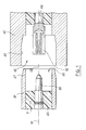
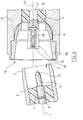
- the connector element located on the left in Figures 4 to 7 is a rigid connector element of axis 1 of the state of the technique, identical to that of Figures 1 to 3.
- It comprises an external conductive body 2, the part of which front 3 in the form of a socket constitutes an external contact, a tubular plastic insulation 4 enclosed in the body and a central conductor 5 located in the body and held by the insulator, extended by a central contact 6 in the form of a pin, which constitutes, with the external contact 3, a male coaxial contact element in projection from the connection face 7 of the connector element.
- the connector element located on the right in Figures 4 to 7, also comprises an electrically conductive body 8, in the form tubular, which defines a central passage 9, a tubular insulator 10 housed in this passage and a central conductor 11 maintained by the insulation inside the body.
- the central conductor 11 is extended by a contact central 12 towards the connection face 13 of the element connector.
- This central contact 12 is constituted by a split socket which has a certain elasticity allowing it to both tighten the pin 6 constituting the central contact of the element associated connector and tolerate misalignments of the two connector elements when they are coupled.
- An external contact 14 is constituted by a hollow part having the external shape of a portion of a sphere, this part hollow being internally traversed by a cylindrical passage 15 and a frustoconical passage 16 coaxial.
- the cylindrical passage 15 allows the central contact 12 to cross the external contact 14 so that the latter surrounds the central contact.
- the frusto-conical passage 16 is provided to receive the contact outside 3 of the associated connector element, as seen in Figures 5, 7 and 8.
- the articulated external contact 14 and the central contact 12 of the connector element form a coaxial contact element female able to cooperate with the male contact element of the element associated connection.
- the female external contact 14 is enclosed in a housing 17 which is delimited by a cylindrical portion 18 likewise diameter than the spherical outer part of the outer contact 14 and by a frustoconical portion 19 opposite the face of connection 13, which connects the cylindrical section 18 to the passage central 9 of the body.
- the cylindrical 18 and frustoconical sections 19 of the housing are tangent to the external surface 20 of the external contact the along two circles 21,22 centered on the axis 23 of the element of connector.
- the axis 23 defines the coupling direction of the element of connector.
- a ring 24 is housed at the mouth of the conductive body outside 8 in an annular recess 25 located in front of the housing 17 provided for the external contact 14.
- This ring 24 which is crimped in said housing by deformation of the front edge 26 of the body, has a radial wall rear 27 forming a stop for the external contact 14, which is thus prevented from leaving his accommodation 17 in which he can nevertheless rotate around the center 28 of the sphere which delimits its outer surface, this center being located on the axis 23 of the connector element.
- the external contact 14 is therefore articulated on the body 8.
- the thickness of the radial wall 27 of the ring 24 is at less equal to the thickness of the front face 29 of the contact articulated exterior 14, so that this front face 29 does not never protrudes inward from the wall inner 30 of the ring.
- the external contact 3 of the connector element partner does not risk striking the front face of the contact articulated exterior 14 during coupling.
- the inner wall 30 of the ring 24 is frustoconical, of so as to ensure, during coupling, the centering of the elements connector by guiding male external contact 3 until that this male external contact 3 comes into contact with the contact articulated female exterior 14.
- the latter being elastic, it can deform sufficiently to support the misalignment of the male central contact 6.
- the coupling can then be completed, the element of male connector fully engaging the element female connector.
- Means of retention (not shown) maintain the connector in its coupled position.
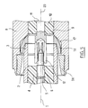
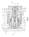
- Figure 8 shows a variant of the connector previously described, mounted in the backplane.
- the female connector element, shown to the right of the FIG. 8 is identical to that of FIGS. 4 to 7.
- a wall 33 which constitutes the rear wall a box in the shape of a drawer, using a ring 34 secured of said wall, on which a helical spring 35 is supported, to push the outer body 8 of the connector element by its flange 36, towards the bottom of the housing intended for receive the drawer.
- This bottom is constituted by a wall 37 on which the element male connector is mounted, its outer body 2 'comprising a base 38 welded to said bottom wall 37.
- the helical spring 35 has the function of ensuring coupling the two connector elements and absorbing a part of the final race of the case in its housing, this stroke being greater than the overlap length of the two connector elements, so as to ensure that all drawer backplane connectors are properly connected.
- the mounting of the element female connector is loose, allowing some movement of this connector element relative to the rear wall 33 of the housing, this in order to allow the connector element female to make up for a slight offset with the element of male connector.
- the male central contact has, at its end, a narrowing of section 38 completed by a bulb 39 of ovoid section, the part directed towards the front of the contact is tapered and forms the end substantially frustoconical 31 'already mentioned.
- the bulb 39 is dimensioned so as to be able to engage in the female contact 12 whose radial elasticity ensures good electrical connection with said bulb by tangent contact with this last.
- the ball joint described here can be achieved by other means, in particular by removing the ring 24 and crimping the conductive body 8 of so that it directly forms the stop preventing contact mobile outside to leave his home.
Abstract
Description
La présente invention concerne un élément de connecteur électrique coaxial à contact mobile et un connecteur coaxial comprenant un tel élément de connecteur.The present invention relates to a connector element electric coaxial with movable contact and a coaxial connector comprising such a connector element.
On sait que les connecteurs électriques coaxiaux connus du
type de celui représenté sur les figures 1 à 3 comprennent deux
éléments de connecteurs qui sont constitués chacun par un corps
électriquement conducteur 41,42, un conducteur central 43,44 situé
dans le corps et isolé de celui-ci et, sur une face 45,46 dite face
d'accouplement de l'élément de connecteur, un élément de contact
coaxial comprenant un contact extérieur 47,48 relié au corps ou
formant partie intégrante du corps et un contact central 49,50 relié
au conducteur central 43,46, le contact extérieur et le contact
central étant coaxiaux, centrés sur l'axe 51,52 de l'élément de
connecteur et permettant d'assurer la connexion avec l'élément de
connecteur électrique associéWe know that the coaxial electrical connectors known from
type of that shown in Figures 1 to 3 include two
connector elements which each consist of a body
electrically conductive 41,42, a
Dans les connecteurs connus, la connexion des deux éléments
de connecteur ne peut avoir lieu que si les deux éléments de
connecteur sont rapprochés l'un de l'autre avec leurs faces
d'accouplement 45,46 en regard et avec leurs axes 51,52 correctement
confondus suivant une direction d'accouplement, comme on le voit sur
les figures 1 et 2.In known connectors, the connection of the two elements
connector can only take place if the two elements of
connector are close to each other with their faces
coupling 45,46 opposite and with their
Cependant, dans certaines circonstances, les deux éléments de connecteur ne peuvent pas être rapprochés l'un de l'autre avec leurs axes d'accouplement 51,52 rigoureusement confondus.However, in certain circumstances, the two elements of connector cannot be pushed together with their coupling axes 51.52 strictly combined.
C'est notamment le cas des connecteurs de fond de panier qui servent à relier des dispositifs électriques montés dans des boítiers en forme de tiroir à des câbles électriques ou à d'autres dispositifs électriques.This is particularly the case for backplane connectors which are used to connect electrical devices mounted in boxes in the shape of a drawer for electric cables or others electrical devices.
En effet, les connecteurs de fond de panier comportent chacun un élément de connecteur monté sur la paroi arrière du boítier et un élément de connecteur monté sur la paroi de fond d'un logement destiné à recevoir ce boítier. The backplane connectors each have a connector element mounted on the rear wall of the housing and a connector element mounted on the bottom wall of a housing intended to receive this case.
Lors de l'insertion du boítier dans le logement, ces deux parois parallèles arrivent au voisinage l'une de l'autre et les deux éléments de connecteur s'accouplent.When inserting the housing into the housing, these two parallel walls arrive in the vicinity of each other and the two connector elements mate.
On comprend que cet accouplement s'effectue sans que l'on puisse voir les éléments de connecteur ni intervenir sur eux, ce que l'on désigne sous le terme d'accouplement "en aveugle".We understand that this coupling takes place without can see the connector elements or intervene on them, which one designates under the term of coupling "blind".
Du fait de cet accouplement "en aveugle", il n'est pas possible de s'apercevoir que les deux éléments de connecteur sont désaxés au moment de leur rapprochement, soit en raison de leur montage, soit en raison d'un léger décalage résultant d'un jeu entre le boítier et le logement.Because of this "blind" coupling, it is not may notice that the two connector elements are misaligned at the time of their reconciliation, either because of their mounting, either due to a slight offset resulting from a play between the housing and housing.
Lorsqu'il ne s'agit que de faibles variations angulaires entre les axes des éléments de connecteur, l'élasticité des contacts extérieur et central de chaque élément de connecteur suffit pour tolérer le défaut d'alignement.When only slight angular variations are involved between the axes of the connector elements, the elasticity of the contacts outside and central of each connector element is sufficient for tolerate misalignment.
En revanche, lorsque les variations angulaires sont plus importantes, par exemple de l'ordre de 5 degrés, comme on le voit à la figure 3, il n'est pas possible d'accoupler les deux éléments de connecteur sous peine de les déformer de manière irréversible ou de les casser.On the other hand, when the angular variations are more important, for example of the order of 5 degrees, as seen in Figure 3, it is not possible to couple the two elements of connector under penalty of irreversibly deforming them or break them.
Le document EP-A-0159116 décrit un élément de connecteur coaxial flottant destiné à être monté en fond de panier. Cet élément de connecteur comprend un contact central mobile et un contact extérieur rigide, fixes l'un par rapport à l'autre, et montés flottants par l'intermédiaire d'un ressort hélicoïdal dans une coupelle de fixation assujettie à un panneau de fond.EP-A-0159116 describes a connector element floating coaxial designed to be mounted in the backplane. This element connector includes a movable central contact and a contact rigid exterior, fixed relative to each other, and mounted floating through a coil spring in a fixing cup fixed to a bottom panel.
Un tel élément de connecteur résout le problème d'alignement exposé ci-dessus mais ne peut être monté que sur un câble dont l'extrémité peut se déplacer pour suivre les mouvements de l'élément de connecteur flottant lors de l'accouplement.Such a connector element solves the alignment problem described above but can only be mounted on a cable whose the tip can move to follow the movements of the element floating connector during coupling.
En outre, cet élément de connecteur est coûteux et encombrant.In addition, this connector element is expensive and bulky.
La présente invention vise à fournir un élément de connecteur coaxial qui résout le problème d'alignement exposé ci-dessus d'une manière différente, de manière à être compatible non seulement avec un câble mais également avec un conducteur coaxial fixe et rigide, tout en étant peu encombrant et d'une réalisation simple et économique.The present invention aims to provide a connector element coaxial which solves the alignment problem outlined above of a in a different way, so as to be compatible not only with a cable but also with a fixed and rigid coaxial conductor, while being compact and of a simple realization and economic.
La présente invention a pour objet un élément de connecteur coaxial apte à s'accoupler par translation suivant une direction d'accouplement avec un élément de connecteur électrique coaxial associé et comportant un corps extérieur électriquement conducteur, destiné à servir de conducteur extérieur, un conducteur central, fixe par rapport au corps extérieur, situé dans le corps et isolé de celui-ci et, sur une face dite face d'accouplement de l'élément de connecteur, un élément de contact coaxial comprenant un contact extérieur relié au conducteur extérieur que constitue le corps et un contact central relié au conducteur central, caractérisé par le fait qu'il comporte, entre le contact extérieur et le corps ou entre le contact central et le conducteur central, une articulation qui permet au contact considéré de s'orienter sans se déformer dans différentes directions formant un angle non nul avec la direction d'accouplement de l'élément de connecteur.The subject of the present invention is a connector element coaxial capable of coupling by translation in a direction coupling with a coaxial electrical connector element associated and comprising an electrically conductive external body, intended to serve as an external conductor, a central conductor, fixed relative to the external body, located in the body and isolated from this and, on a face called the coupling face of the element of connector, a coaxial contact element comprising a contact external connected to the external conductor which constitutes the body and a central contact connected to the central conductor, characterized by the fact that it comprises, between the external contact and the body or between the central contact and the central conductor, a joint that allows the contact in question to orient itself without deforming in different directions forming a non-zero angle with the direction of the connector element.
Ainsi, on peut accoupler l'élément de connecteur selon l'invention avec un élément de connecteur associé dont l'axe forme un angle non nul avec l'axe de l'élément de connecteur selon l'invention.Thus, one can couple the connector element according to the invention with an associated connector element whose axis forms a non-zero angle with the axis of the connector element along the invention.
Au début de la phase d'accouplement entre les deux éléments de connecteur, le contact extérieur et/ou le contact central de l'élément de connecteur selon l'invention s'oriente de manière à se centrer sur l'axe de l'élément de connecteur associé, après quoi la phase d'accouplement peut s'achever dans les mêmes conditions que si l'élément de connecteur associé se présentait dans la direction d'accouplement de l'élément de connecteur selon l'invention.At the start of the mating phase between the two elements connector, the external contact and / or the central contact of the connector element according to the invention is oriented so as to be center on the axis of the associated connector element, after which the mating phase can be completed under the same conditions as if the associated connector element was facing in the direction for coupling the connector element according to the invention.
L'élément de connecteur selon l'invention présente l'avantage de conserver les caractéristiques électriques d'un connecteur traditionnel, notamment en ce qui concerne le blindage électromagnétique du fait que l'accouplement des contacts s'effectue dans de bonnes conditions, ce qui n'est pas le cas d'un élément de connecteur rigide qui se déforme en cas d'accouplement désaligné.The connector element according to the invention has the advantage to keep the electrical characteristics of a connector traditional, especially with regard to armor electromagnetic because the contacts are coupled in good conditions, which is not the case for an element of rigid connector which deforms in the event of misaligned coupling.
De préférence, l'élément de connecteur selon l'invention comprend une articulation au moins sur son contact extérieur car ce dernier présente des dimensions plus importantes que le contact intérieur et est généralement le moins apte à se déformer élastiquement pour tolérer un défaut d'alignement des deux éléments de connecteur lors de leur accouplement.Preferably, the connector element according to the invention includes a joint at least on its external contact because this the latter has larger dimensions than the contact interior and is generally least able to deform elastically to tolerate a misalignment of the two elements connector when they are coupled.
Dans ce cas, le contact central mâle du connecteur, qu'il se trouve sur l'élément de connecteur muni du contact extérieur articulé ou sur l'élément de connecteur associé, peut comporter un bulbe à son extrémité, de manière à constituer une liaison rotule avec le contact central femelle de l'autre élément de connecteur, du fait que ledit bulbe peut prendre différentes orientations à l'intérieur dudit contact femelle.In this case, the male central contact of the connector, whether found on connector element with external contact articulated or on the associated connector element, may include a bulb at its end, so as to constitute a ball joint with the female central contact of the other connector element, of the fact that said bulb can take different orientations to inside said female contact.
Ainsi, ni les contacts extérieurs ni les contacts centraux du connecteur n'ont à subir de contrainte en cas d'accouplement désaligné des deux éléments de connecteur.Thus, neither the external contacts nor the central contacts of the connector need not be stressed in case of coupling misaligned from the two connector elements.
Dans un mode de réalisation préféré de l'invention, l'articulation qui permet l'orientation du contact est une liaison rotule qui autorise une rotation dudit contact autour d'un point fixe situé sensiblement sur l'axe de l'élément de connecteur.In a preferred embodiment of the invention, the joint which allows the orientation of the contact is a connection ball which allows rotation of said contact around a point fixed located substantially on the axis of the connector element.
De préférence, cette rotation s'effectue à l'intérieur d'un angle solide d'environ 10 degrés d'ouverture.Preferably, this rotation takes place inside a solid angle of about 10 degrees of opening.
Par exemple, la liaison rotule est obtenue en donnant une forme sphérique à la surface extérieure du contact et en enfermant ce contact dans un logement dont la paroi intérieure est tangente à la surface extérieure sphérique du contact. Avantageusement, le contact est engagé légèrement en force dans le logement pour assurer une meilleure liaison électrique entre ledit contact et ledit logement.For example, the ball joint is obtained by giving a spherical shape on the outside surface of the contact and enclosing this contact in a housing whose inner wall is tangent to the spherical outer surface of the contact. Advantageously, the contact is engaged slightly in force in the housing to ensure a better electrical connection between said contact and said housing.
La présente invention a également pour objet un connecteur électrique coaxial comportant deux éléments de connecteur dont l'un au moins comporte une articulation telle que décrite ci-dessus.The present invention also relates to a connector electric coaxial comprising two connector elements, one of which at least has a hinge as described above.
Dans le but de mieux faire comprendre l'invention on va en décrire maintenant un mode de réalisation donné à titre d'exemple non limitatif en référence au dessin annexé dans lequel :
- les figures 1 à 3 illustrent l'état de la technique déjà commenté,
- la figure 4 représente, en coupe axiale, un connecteur électrique coaxial selon l'invention avant accouplement des deux éléments de connecteur alignés,
- la figure 5 est une vue analogue à la figure 4 après accouplement des deux éléments de connecteur alignés,
- la figure 6 est une vue analogue à la figure 4 montrant les deux éléments de connecteur désalignés,
- la figure 7 est une vue analogue à la figure 6 après accouplement des deux éléments de connecteur désalignés, et
- la figure 8 est une vue analogue à la figure 7 représentant une variante du connecteur.
- FIGS. 1 to 3 illustrate the state of the art already commented on,
- FIG. 4 represents, in axial section, a coaxial electrical connector according to the invention before coupling of the two aligned connector elements,
- FIG. 5 is a view similar to FIG. 4 after coupling of the two aligned connector elements,
- FIG. 6 is a view similar to FIG. 4 showing the two misaligned connector elements,
- FIG. 7 is a view similar to FIG. 6 after coupling of the two misaligned connector elements, and
- Figure 8 is a view similar to Figure 7 showing a variant of the connector.
L'élément de connecteur situé à gauche sur les figures 4 à 7
est un élément de connecteur rigide d'axe 1 de l'état de la
technique, identique à celui des figures 1 à 3.The connector element located on the left in Figures 4 to 7
is a rigid connector element of
Il comporte un corps conducteur extérieur 2 dont la partie
frontale 3 en forme de douille constitue un contact extérieur, un
isolant tubulaire 4 en matière plastique enfermé dans le corps et un
conducteur central 5 situé dans le corps et maintenu par l'isolant,
prolongé par un contact central 6 en forme de broche, qui constitue,
avec le contact extérieur 3, un élément de contact coaxial mâle en
saillie de la face de connexion 7 de l'élément de connecteur.It comprises an external
L'élément de connecteur situé à droite sur les figures 4 à 7,
comporte également un corps 8 électriquement conducteur, de forme
tubulaire, qui délimite un passage central 9, un isolant tubulaire
10 logé dans ce passage et un conducteur central 11 maintenu par
l'isolant à l'intérieur du corps.The connector element located on the right in Figures 4 to 7,
also comprises an electrically
Le conducteur central 11 est prolongé par un contact
central 12 en direction de la face de connexion 13 de l'élément de
connecteur.The
Ce contact central 12 est constitué par une douille fendue
qui présente une certaine élasticité lui permettant à la fois de
serrer la broche 6 constituant le contact central de l'élément de
connecteur associé et de tolérer des désalignements des deux
éléments de connecteur lors de leur accouplement.This
Un contact extérieur 14 est constitué par une pièce creuse
présentant la forme extérieure d'une portion de sphère, cette pièce
creuse étant traversée intérieurement par un passage cylindrique 15
et un passage tronconique 16 coaxiaux. An
Le passage cylindrique 15 permet au contact central 12 de
traverser le contact extérieur 14 de sorte que ce dernier entoure le
contact central.The
Le passage tronconique 16 est prévu pour recevoir le contact
extérieur 3 de l'élément de connecteur associé, comme on le voit aux
figures 5, 7 et 8.The frusto-
Le contact extérieur articulé 14 et le contact central 12 de
l'élément de connecteur forment un élément de contact coaxial
femelle apte à coopérer avec l'élément de contact mâle de l'élément
de connexion associé.The articulated
Le contact extérieur femelle 14 est enfermé dans un
logement 17 qui est délimité par une portion cylindrique 18 de même
diamètre que la partie extérieure sphérique du contact extérieur 14
et par une portion tronconique 19 opposée à la face de
connexion 13, qui raccorde le tronçon cylindrique 18 au passage
central 9 du corps.The female
Les tronçons cylindrique 18 et tronconique 19 du logement
sont tangents à la surface extérieure 20 du contact extérieur le
long de deux cercles 21,22 centrés sur l'axe 23 de l'élément de
connecteur.The cylindrical 18 and
L'axe 23 définit la direction d'accouplement de l'élément de
connecteur.The
Une bague 24 est logée à l'embouchure du corps conducteur
extérieur 8 dans un évidement annulaire 25 situé en avant du
logement 17 prévu pour le contact extérieur 14.A
Cette bague 24, qui est sertie dans ledit logement par
déformation du bord frontal 26 du corps, présente une paroi radiale
arrière 27 formant butée pour le contact extérieur 14, lequel est
ainsi empêché de quitter son logement 17 dans lequel il peut
néanmoins effectuer des rotations autour du centre 28 de la sphère
qui délimite sa surface extérieure, ce centre étant situé sur
l'axe 23 de l'élément de connecteur.This
Le contact extérieur 14 est donc articulé sur le corps 8.The
L'épaisseur de la paroi radiale 27 de la bague 24 est au
moins égale à l'épaisseur de la face frontale 29 du contact
extérieur articulé 14, de manière que cette face frontale 29 ne se
situe jamais en saillie vers l'intérieur par rapport à la paroi
intérieure 30 de la bague.The thickness of the
Ainsi, le contact extérieur 3 de l'élément de connecteur
associé ne risque pas de heurter la face frontale du contact
extérieur articulé 14 lors de l'accouplement.Thus, the
La paroi intérieure 30 de la bague 24 est tronconique, de
manière à assurer, lors de l'accouplement, le centrage des éléments
de connecteur par guidage du contact extérieur mâle 3 jusqu'à ce
que ce contact extérieur mâle 3 vienne au contact du contact
extérieur femelle articulé 14.The
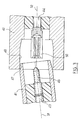
Lors d'un accouplement conventionnel, c'est-à-dire lorsque
les deux éléments de connecteur se présentent avec leurs axes
d'accouplement 1,23 confondus, le contact extérieur mâle 3 et le
contact central mâle 6 de l'élément de connecteur associé viennent
prendre place dans le contact extérieur femelle articulé 14 et le
contact central femelle 12, comme on le voit sur la figure 5.During conventional mating, i.e. when
the two connector elements are presented with their axes
1.23 coupling combined, the male
Lors d'un accouplement désaligné, c'est-à-dire lorsque les
éléments de connecteurs se présentent avec leurs axes 1,23 sécants,
comme on le voit sur la figure 6, l'élément de connecteur associé
pénètre d'abord dans la bague sertie 24 dont la paroi intérieure
tronconique 30 guide le contact extérieur mâle 3 jusqu'à ce qu'il
atteigne le contact extérieur femelle articulé 14. A ce stade de
l'accouplement, le contact central mâle en forme de broche 6 pénètre
par son extrémité tronconique 31 dans le contact central femelle 12
de l'élément de connecteur selon l'invention en étant guidé par
l'embouchure chanfreinée 32 dudit contact central femelle.During a misaligned coupling, that is to say when the
connector elements are presented with their 1.23 secant axes,
as seen in Figure 6, the associated connector element
first enters the
Ce dernier étant élastique, il peut se déformer suffisamment
pour supporter le désalignement du contact central mâle 6.The latter being elastic, it can deform sufficiently
to support the misalignment of the male
Simultanément, lorsque le contact extérieur mâle 3 arrive en
appui contre le contact extérieur femelle articulé 14, il en
repousse la partie inférieure (par rapport au dessin), ce qui
provoque une rotation du contact extérieur femelle, mobile à
l'intérieur de son logement. Ledit contact extérieur femelle
articulé 14 s'aligne alors automatiquement avec l'axe l'élément de
connecteur associé, comme on le voit sur la figure 7.Simultaneously, when the male
L'accouplement peut ensuite s'achever, l'élément de connecteur mâle s'engageant complètement dans l'élément de connecteur femelle. Des moyens de rétention (non représentés) assurent le maintien du connecteur dans sa position accouplée.The coupling can then be completed, the element of male connector fully engaging the element female connector. Means of retention (not shown) maintain the connector in its coupled position.
Dans le cas d'un connecteur de fond de panier, c'est-à-dire dont les deux éléments de connecteur sont montés sur des panneaux, l'un sur la paroi de fond d'un logement de tiroir, l'autre sur la paroi arrière d'un boítier en forme de tiroir destiné à être inséré dans ce logement de tiroir, il n'est pas utile de prévoir de moyens de rétention propres au connecteur car le maintien du tiroir enfoncé dans son logement suffit à assurer la rétention de tous les connecteurs situés à l'arrière du tiroir.In the case of a backplane connector, i.e. the two connector elements of which are mounted on panels, one on the bottom wall of a drawer housing, the other on the rear wall of a box in the form of a drawer intended to be inserted in this drawer housing, it is not useful to provide means of retention specific to the connector because keeping the drawer pressed in its housing is sufficient to ensure the retention of all connectors located at the back of the drawer.
La figure 8 représente une variante du connecteur précédemment décrit, monté en fond de panier.Figure 8 shows a variant of the connector previously described, mounted in the backplane.
L'élément de connecteur femelle, représenté à droite de la figure 8, est identique à celui des figures 4 à 7.The female connector element, shown to the right of the FIG. 8 is identical to that of FIGS. 4 to 7.
Il est monté sur une paroi 33 qui constitue la paroi arrière
d'un boítier en forme de tiroir, à l'aide d'une bague 34 solidaire
de ladite paroi, sur laquelle un ressort hélicoïdal 35 prend appui,
pour repousser le corps extérieur 8 de l'élément de connecteur par
sa collerette 36, en direction du fond du logement destiné à
recevoir le tiroir.It is mounted on a
Ce fond est constitué par une paroi 37 sur laquelle l'élément
de connecteur mâle est monté, son corps extérieur 2' comportant une
embase 38 soudée sur ladite paroi de fond 37.This bottom is constituted by a
Le ressort hélicoïdal 35 a pour fonction d'assurer
l'accouplement des deux éléments de connecteur et d'absorber une
partie de la course finale du boítier dans son logement, cette
course étant supérieure à la longueur de recouvrement des deux
éléments de connecteur, de manière à assurer que tous les
connecteurs de fond de panier du tiroir sont correctement connectés.The
Comme on le voit sur la figure 8, le montage de l'élément de
connecteur femelle est lâche, ce qui autorise un certain mouvement
de cet élément de connecteur par rapport à la paroi arrière 33 du
boítier, ce, dans le but de permettre à l'élément de connecteur
femelle de rattraper un éventuel léger décalage avec l'élément de
connecteur mâle.As seen in Figure 8, the mounting of the element
female connector is loose, allowing some movement
of this connector element relative to the
Ce rattrapage est assuré par les surfaces de centrage prévues
entre les deux éléments de connecteur, à savoir, sur l'élément de
connecteur femelle, la paroi tronconique 30 de la bague 24 et
l'embouchure tronconique 32 du contact central 12 et sur l'élément
de connecteur mâle, le tronçon avant tronconique du contact
extérieur 3 et l'extrémité sensiblement tronconique 31' du contact
central 6'.This catching up is ensured by the centering surfaces provided
between the two connector elements, i.e., on the connector element
female connector, the
Au moment du centrage des deux éléments de connecteur, les axes de ceux-ci, qui devraient être confondus, sont sécants.When centering the two connector elements, the axes of these, which should be confused, are intersecting.
L'articulation du contact extérieur femelle lui permet de s'accommoder de ce désalignement en préservant les contacts extérieurs de toute contrainte de flexion, comme cela a été décrit en référence aux figures 4 à 7.The articulation of the female external contact allows it to to deal with this misalignment while preserving the contacts outside of any bending stress, as described with reference to Figures 4 to 7.
Dans la variante de la figure 8, le contact central mâle
comporte, à son extrémité, un rétrécissement de section 38 terminé
par un bulbe 39 de section ovoïdale, dont la partie dirigée vers
l'avant du contact est effilée et forme l'extrémité sensiblement
tronconique 31' déjà mentionnée.In the variant of FIG. 8, the male central contact
has, at its end, a narrowing of
Le bulbe 39 est dimensionné de manière à pouvoir s'engager
dans le contact femelle 12 dont l'élasticité radiale assure une
bonne liaison électrique avec ledit bulbe par contact tangent avec
ce dernier.The
La forme quasi sphérique du bulbe autour de cette zone de
contact tangent, ainsi que le dégagement procuré par le
rétrécissement de section 38, autorisent une rotation dudit bulbe à
l'intérieur du contact femelle de sorte que la liaison entre le
contact mâle et le contact femelle s'apparente à une liaison rotule.The almost spherical shape of the bulb around this area of
tangent contact, as well as the clearance provided by the
narrowing
Ainsi, les contacts centraux sont, comme les contacts extérieurs, préservés de toute contrainte liée au fait que les deux éléments de connecteur s'accouplent en étant désalignés.So the central contacts are, like the contacts outside, free from any constraints linked to the fact that the two connector elements mate when misaligned.
Il est bien entendu que le mode de réalisation qui vient d'être décrit ne présente aucun caractère limitatif et qu'il pourra recevoir toutes modifications désirables sans sortir pour cela du cadre de l'invention.It is understood that the embodiment which comes to be described has no limiting nature and that it may receive any desirable changes without leaving the part of the invention.
En particulier, il est clair que la liaison rotule décrite
ici pourra être réalisée par d'autres moyens, notamment en
supprimant la bague 24 et en sertissant le corps conducteur 8 de
manière qu'il forme directement la butée empêchant le contact
extérieur mobile de quitter son logement. In particular, it is clear that the ball joint described
here can be achieved by other means, in particular by
removing the
En outre, si le contact central femelle 12 présente une
élasticité insuffisante, une liaison rotule similaire à celle
décrite pour le contact extérieur 14 pourrait être prévue entre ce
contact central et le conducteur central.In addition, if the female
De plus, il est bien évident que le sexe des contacts décrits ici n'a aucun caractère limitatif.In addition, it is obvious that the gender of the contacts described here is in no way limiting.
Claims (7)
Applications Claiming Priority (2)
| Application Number | Priority Date | Filing Date | Title |
|---|---|---|---|
| FR9700529A FR2758662B1 (en) | 1997-01-20 | 1997-01-20 | MOBILE CONTACT COAXIAL ELECTRIC CONNECTOR ELEMENT AND COAXIAL ELECTRIC CONNECTOR INCLUDING SUCH A CONNECTOR ELEMENT |
| FR9700529 | 1997-01-20 |
Publications (1)
| Publication Number | Publication Date |
|---|---|
| EP0854547A1 true EP0854547A1 (en) | 1998-07-22 |
Family
ID=9502758
Family Applications (1)
| Application Number | Title | Priority Date | Filing Date |
|---|---|---|---|
| EP98400097A Withdrawn EP0854547A1 (en) | 1997-01-20 | 1998-01-20 | Electrical coaxial connecting element with a movable contact and electrical coaxial connector with such a connecting element |
Country Status (3)
| Country | Link |
|---|---|
| US (1) | US5980290A (en) |
| EP (1) | EP0854547A1 (en) |
| FR (1) | FR2758662B1 (en) |
Cited By (3)
| Publication number | Priority date | Publication date | Assignee | Title |
|---|---|---|---|---|
| WO2000052788A1 (en) * | 1999-03-02 | 2000-09-08 | Huber+Suhner Ag | Coaxial connection for a printed circuit board |
| US9281641B2 (en) | 2013-10-29 | 2016-03-08 | Telegaertner Karl Gaertner Gmbh | Connecting device for electrically connecting two circuit boards |
| EP2834888B1 (en) * | 2012-04-05 | 2017-08-30 | Huber+Suhner AG | Printed circuit board coaxial connector |
Families Citing this family (43)
| Publication number | Priority date | Publication date | Assignee | Title |
|---|---|---|---|---|
| DE19653676C1 (en) * | 1996-12-16 | 1998-01-29 | Siemens Ag | Connection between medium voltage switch zones |
| US6196856B1 (en) * | 1998-06-22 | 2001-03-06 | The Whitaker Corporation | Floating connector assembly |
| JP4365949B2 (en) | 1999-08-25 | 2009-11-18 | モレックス インコーポレイテド | Board connector |
| FR2803108B1 (en) * | 1999-12-22 | 2002-02-08 | Alstom | INTERCONNECTION SYSTEM BETWEEN ELECTRICAL CELLS, MEDIUM OR HIGH VOLTAGE, IN BOXES |
| US6343958B1 (en) * | 2001-04-05 | 2002-02-05 | Adc Telecommunications, Inc. | Compressive collar |
| US6659786B2 (en) * | 2001-04-25 | 2003-12-09 | Tyco Electronics Amp Gmbh | Electrical connector |
| US6637949B2 (en) * | 2001-06-01 | 2003-10-28 | Adc Telecommunications, Inc. | Method and apparatus for multi-directional fiber optic connection |
| GB2388256B (en) * | 2002-04-30 | 2005-10-05 | Otter Controls Ltd | Improvements relating to cordless electrical appliances |
| US6699054B1 (en) | 2003-01-15 | 2004-03-02 | Applied Engineering Products, Inc. | Float mount coaxial connector |
| US7077697B2 (en) * | 2004-09-09 | 2006-07-18 | Corning Gilbert Inc. | Snap-in float-mount electrical connector |
| FR2905528B1 (en) * | 2006-08-31 | 2008-10-31 | Radiall Sa | COAXIAL CONNECTOR FOR CONNECTING TWO CIRCUIT BOARDS. |
| DE102007059254B3 (en) * | 2007-12-08 | 2009-04-30 | Harting Electronics Gmbh & Co. Kg | Swiveling PCB connector |
| US8622762B2 (en) | 2010-11-22 | 2014-01-07 | Andrew Llc | Blind mate capacitively coupled connector |
| CH704592A2 (en) * | 2011-03-08 | 2012-09-14 | Huber+Suhner Ag | RF coaxial connector. |
| TWI514687B (en) * | 2011-07-15 | 2015-12-21 | Hon Hai Prec Ind Co Ltd | Electrical connector and connector terminal |
| US9219461B2 (en) | 2011-12-22 | 2015-12-22 | Commscope Technologies Llc | Capacitive blind-mate module interconnection |
| US8747152B2 (en) | 2012-11-09 | 2014-06-10 | Andrew Llc | RF isolated capacitively coupled connector |
| US8801460B2 (en) | 2012-11-09 | 2014-08-12 | Andrew Llc | RF shielded capacitively coupled connector |
| BR102013000076A2 (en) * | 2013-01-02 | 2014-08-19 | Bosch Do Brasil | CONNECTOR FOR AUTOMOTIVE VEHICLE ELECTRIC HARNESS WITH TERMINALS THROUGH A FLANGE |
| US9735521B2 (en) | 2013-01-09 | 2017-08-15 | Amphenol Corporation | Float adapter for electrical connector |
| US9039433B2 (en) * | 2013-01-09 | 2015-05-26 | Amphenol Corporation | Electrical connector assembly with high float bullet adapter |
| US9356374B2 (en) | 2013-01-09 | 2016-05-31 | Amphenol Corporation | Float adapter for electrical connector |
| US9009960B2 (en) | 2013-01-25 | 2015-04-21 | Commscope Technologies Llc | Method of manufacturing a curved transition surface of an inner contact |
| US8882539B2 (en) | 2013-03-14 | 2014-11-11 | Amphenol Corporation | Shunt for electrical connector |
| WO2014172250A1 (en) * | 2013-04-18 | 2014-10-23 | Fci Asia Pte. Ltd | Electrical connector system |
| DE202013006067U1 (en) * | 2013-07-05 | 2013-08-12 | Rosenberger Hochfrequenztechnik Gmbh & Co. Kg | Connectors |
| CN103606784B (en) * | 2013-11-20 | 2016-05-25 | 中国电子科技集团公司第二十三研究所 | A kind of float connector |
| WO2017058230A1 (en) * | 2015-10-01 | 2017-04-06 | Intelliserv International Holding, Ltd. | Communicative coupler for a well system |
| JP6804888B2 (en) * | 2016-07-27 | 2020-12-23 | ヒロセ電機株式会社 | Coaxial connector |
| JP6840594B2 (en) * | 2017-03-27 | 2021-03-10 | モレックス エルエルシー | Connector assembly |
| US10008802B1 (en) * | 2017-04-24 | 2018-06-26 | Eaton Intelligent Power Limited | Receptacle frames for adapting a float range capability of a blind-mate connector and related systems |
| JP6689235B2 (en) * | 2017-07-11 | 2020-04-28 | イリソ電子工業株式会社 | connector |
| US10566715B2 (en) | 2017-09-29 | 2020-02-18 | Apple Inc. | Reduced net force electrical connectors |
| US10355402B2 (en) * | 2017-09-29 | 2019-07-16 | Apple Inc. | Axisymmetric magnetic articulating connector |
| KR102608751B1 (en) * | 2017-12-18 | 2023-12-04 | 타이코에이엠피 주식회사 | Connector assembly and manufacturing method of socket for connector assembly |
| KR101926502B1 (en) * | 2018-03-27 | 2018-12-07 | 주식회사 기가레인 | board mating connector including PIMD enhanced signal contact part |
| KR101926503B1 (en) * | 2018-03-27 | 2018-12-07 | 주식회사 기가레인 | Board mating connector in which the signal contact part and ground contact part are interlock |
| CN110829065B (en) * | 2018-08-10 | 2021-04-20 | 鸿富锦精密电子(天津)有限公司 | Floating orientation support and electronic assembly |
| KR102118829B1 (en) * | 2019-07-26 | 2020-06-04 | 주식회사 기가레인 | Board-mating connector |
| CN112787120A (en) * | 2019-11-11 | 2021-05-11 | 康普技术有限责任公司 | Coaxial connector and board-to-board connector assembly |
| CN112787121A (en) * | 2019-11-11 | 2021-05-11 | 康普技术有限责任公司 | Coaxial connector and board-to-board connector assembly |
| US11811174B2 (en) | 2020-09-25 | 2023-11-07 | Apple Inc. | Low-profile axisymmetric power connectors |
| JP2023084216A (en) * | 2021-12-07 | 2023-06-19 | 日本航空電子工業株式会社 | Floating connector and floating connector assembly |
Citations (5)
| Publication number | Priority date | Publication date | Assignee | Title |
|---|---|---|---|---|
| LU55473A1 (en) * | 1967-03-01 | 1968-04-23 | ||
| EP0159116A2 (en) * | 1984-03-26 | 1985-10-23 | AMP INCORPORATED (a New Jersey corporation) | Floating connector assembly |
| WO1989004984A1 (en) * | 1987-11-23 | 1989-06-01 | Hughes Aircraft Company | Self-aligning precision guide pin |
| GB2218271A (en) * | 1988-05-06 | 1989-11-08 | Marconi Instruments Ltd | Connector |
| US5276750A (en) * | 1993-04-02 | 1994-01-04 | The Whitaker Corporation | Connectors having translational and rotational compliance about the leading edge |
Family Cites Families (6)
| Publication number | Priority date | Publication date | Assignee | Title |
|---|---|---|---|---|
| US2519933A (en) * | 1944-09-02 | 1950-08-22 | Gen Electric | Rotatable joint for coaxial cables |
| US2972728A (en) * | 1958-06-09 | 1961-02-21 | Fred H Cole | Electrical plug having self-aligning terminal pins |
| GB2024531A (en) * | 1978-06-14 | 1980-01-09 | Green Precision Ind Ltd Lee | Plug and receptacle connectors |
| SU1072159A1 (en) * | 1982-12-20 | 1984-02-07 | Предприятие П/Я В-2827 | Connector assembly for interblock mating |
| US4697859A (en) * | 1986-08-15 | 1987-10-06 | Amp Incorporated | Floating coaxial connector |
| US4815986A (en) * | 1987-08-14 | 1989-03-28 | Lucas Weinschel, Inc. | Self-aligning blind mate connector |
-
1997
- 1997-01-20 FR FR9700529A patent/FR2758662B1/en not_active Expired - Fee Related
-
1998
- 1998-01-20 EP EP98400097A patent/EP0854547A1/en not_active Withdrawn
- 1998-01-20 US US09/009,464 patent/US5980290A/en not_active Expired - Fee Related
Patent Citations (5)
| Publication number | Priority date | Publication date | Assignee | Title |
|---|---|---|---|---|
| LU55473A1 (en) * | 1967-03-01 | 1968-04-23 | ||
| EP0159116A2 (en) * | 1984-03-26 | 1985-10-23 | AMP INCORPORATED (a New Jersey corporation) | Floating connector assembly |
| WO1989004984A1 (en) * | 1987-11-23 | 1989-06-01 | Hughes Aircraft Company | Self-aligning precision guide pin |
| GB2218271A (en) * | 1988-05-06 | 1989-11-08 | Marconi Instruments Ltd | Connector |
| US5276750A (en) * | 1993-04-02 | 1994-01-04 | The Whitaker Corporation | Connectors having translational and rotational compliance about the leading edge |
Cited By (3)
| Publication number | Priority date | Publication date | Assignee | Title |
|---|---|---|---|---|
| WO2000052788A1 (en) * | 1999-03-02 | 2000-09-08 | Huber+Suhner Ag | Coaxial connection for a printed circuit board |
| EP2834888B1 (en) * | 2012-04-05 | 2017-08-30 | Huber+Suhner AG | Printed circuit board coaxial connector |
| US9281641B2 (en) | 2013-10-29 | 2016-03-08 | Telegaertner Karl Gaertner Gmbh | Connecting device for electrically connecting two circuit boards |
Also Published As
| Publication number | Publication date |
|---|---|
| FR2758662B1 (en) | 1999-03-26 |
| FR2758662A1 (en) | 1998-07-24 |
| US5980290A (en) | 1999-11-09 |
Similar Documents
| Publication | Publication Date | Title |
|---|---|---|
| EP0854547A1 (en) | Electrical coaxial connecting element with a movable contact and electrical coaxial connector with such a connecting element | |
| EP0663706B1 (en) | Microminiature coaxial connector with snap fastening | |
| EP0491626B1 (en) | Electrical coaxial connector | |
| EP1154527B1 (en) | Device to connect a coaxial cable to a printed circuit board | |
| CA1329420C (en) | Electric connector | |
| EP1028490A1 (en) | Coaxial connector for connecting two printed circuit boards | |
| FR2746151A1 (en) | DEVICE FOR THE PROTECTION AND GUIDE OF AN ASSOCIATED ELONGATED COMPONENT, AT THE JOINT, WITH TWO RIGID ELEMENTS JOINTED ONE TO THE OTHER, AND THEIR INDUSTRIAL APPLICATIONS | |
| EP1054479A1 (en) | Device for electrically connecting a coaxial line to a printed circuit board | |
| EP2104963B1 (en) | Watertight electric connection device including two conjugated connection members | |
| EP0287411B1 (en) | Removable ball joint | |
| EP1057228B1 (en) | Electrical connector contact pin | |
| FR2911819A1 (en) | Headrest system for seat of vehicle, has headrest supported by maintaining rod, and electrical plug-in connectors with contact elements including rotational symmetry with respect to median axis and assembling direction | |
| EP0312438A1 (en) | Self stripping connector for electrical conductor | |
| EP0500466A2 (en) | Shutting device for the contact cavity of an electrical or optical connector | |
| EP0685911A1 (en) | Device for connecting an electrical coaxial connector and electrical connector including such connecting element | |
| EP0884806B1 (en) | Electrical connector with improved contact security | |
| EP1020677A1 (en) | Connector assembly | |
| EP0172779B1 (en) | Multipole electrical connector | |
| EP0820117A1 (en) | Device for producing a splice | |
| FR2709607A1 (en) | Coaxial electrical connector with screw locking. | |
| EP0398770A1 (en) | Connection device for a coaxial cable, particularly for connecting an antenna to a car radio | |
| EP1202399A2 (en) | Road vehicle electric element | |
| EP0345189A1 (en) | Electrical connector | |
| FR2797102A1 (en) | Connector used for miniature contact comprises centering system having metallic envelope with cutouts, and three elastic tabs centering contact section in cell | |
| FR2678113A1 (en) | Electrical connector system |
Legal Events
| Date | Code | Title | Description |
|---|---|---|---|
| PUAI | Public reference made under article 153(3) epc to a published international application that has entered the european phase |
Free format text: ORIGINAL CODE: 0009012 |
|
| AK | Designated contracting states |
Kind code of ref document: A1 Designated state(s): BE CH DE FR GB IT LI NL SE |
|
| AX | Request for extension of the european patent |
Free format text: AL;LT;LV;MK;RO;SI |
|
| 17P | Request for examination filed |
Effective date: 19980902 |
|
| AKX | Designation fees paid |
Free format text: BE CH DE FR GB IT LI NL SE |
|
| RBV | Designated contracting states (corrected) |
Designated state(s): BE CH DE FR GB IT LI NL SE |
|
| STAA | Information on the status of an ep patent application or granted ep patent |
Free format text: STATUS: THE APPLICATION IS DEEMED TO BE WITHDRAWN |
|
| 18D | Application deemed to be withdrawn |
Effective date: 20010801 |