EP0854089B1 - Verfahren zum Verpacken eines gelöstes Gas enthaltenden Getränkes - Google Patents
Verfahren zum Verpacken eines gelöstes Gas enthaltenden Getränkes Download PDFInfo
- Publication number
- EP0854089B1 EP0854089B1 EP97309758A EP97309758A EP0854089B1 EP 0854089 B1 EP0854089 B1 EP 0854089B1 EP 97309758 A EP97309758 A EP 97309758A EP 97309758 A EP97309758 A EP 97309758A EP 0854089 B1 EP0854089 B1 EP 0854089B1
- Authority
- EP
- European Patent Office
- Prior art keywords
- insert
- beverage
- container
- headspace
- hollow
- Prior art date
- Legal status (The legal status is an assumption and is not a legal conclusion. Google has not performed a legal analysis and makes no representation as to the accuracy of the status listed.)
- Expired - Lifetime
Links
- 235000013361 beverage Nutrition 0.000 title claims description 162
- 238000000034 method Methods 0.000 title claims description 40
- 238000004806 packaging method and process Methods 0.000 title claims description 7
- 239000002775 capsule Substances 0.000 claims description 65
- 239000007789 gas Substances 0.000 claims description 53
- IJGRMHOSHXDMSA-UHFFFAOYSA-N Atomic nitrogen Chemical compound N#N IJGRMHOSHXDMSA-UHFFFAOYSA-N 0.000 claims description 28
- 239000012530 fluid Substances 0.000 claims description 21
- 238000011161 development Methods 0.000 claims description 18
- 229910052757 nitrogen Inorganic materials 0.000 claims description 14
- 239000007788 liquid Substances 0.000 claims description 13
- 238000007789 sealing Methods 0.000 claims description 10
- 239000000853 adhesive Substances 0.000 claims description 9
- 230000001070 adhesive effect Effects 0.000 claims description 9
- 230000000717 retained effect Effects 0.000 claims description 8
- 238000004826 seaming Methods 0.000 claims description 8
- 230000015572 biosynthetic process Effects 0.000 claims description 6
- 238000004891 communication Methods 0.000 claims description 4
- 229920003023 plastic Polymers 0.000 claims description 3
- 239000004033 plastic Substances 0.000 claims description 3
- 238000009928 pasteurization Methods 0.000 claims description 2
- 230000000694 effects Effects 0.000 description 23
- 238000007667 floating Methods 0.000 description 20
- 238000005516 engineering process Methods 0.000 description 6
- 239000011521 glass Substances 0.000 description 6
- 238000012986 modification Methods 0.000 description 5
- 230000004048 modification Effects 0.000 description 5
- 238000004519 manufacturing process Methods 0.000 description 4
- 239000000463 material Substances 0.000 description 3
- 235000013405 beer Nutrition 0.000 description 2
- 238000009924 canning Methods 0.000 description 2
- 238000006243 chemical reaction Methods 0.000 description 2
- 230000008020 evaporation Effects 0.000 description 2
- 238000001704 evaporation Methods 0.000 description 2
- 230000001747 exhibiting effect Effects 0.000 description 2
- 239000000696 magnetic material Substances 0.000 description 2
- 230000035515 penetration Effects 0.000 description 2
- 230000035939 shock Effects 0.000 description 2
- 238000013459 approach Methods 0.000 description 1
- 238000011109 contamination Methods 0.000 description 1
- 230000035622 drinking Effects 0.000 description 1
- 239000000203 mixture Substances 0.000 description 1
- 230000003647 oxidation Effects 0.000 description 1
- 238000007254 oxidation reaction Methods 0.000 description 1
- 230000008855 peristalsis Effects 0.000 description 1
- 238000012545 processing Methods 0.000 description 1
Images

Classifications
-
- B—PERFORMING OPERATIONS; TRANSPORTING
- B65—CONVEYING; PACKING; STORING; HANDLING THIN OR FILAMENTARY MATERIAL
- B65D—CONTAINERS FOR STORAGE OR TRANSPORT OF ARTICLES OR MATERIALS, e.g. BAGS, BARRELS, BOTTLES, BOXES, CANS, CARTONS, CRATES, DRUMS, JARS, TANKS, HOPPERS, FORWARDING CONTAINERS; ACCESSORIES, CLOSURES, OR FITTINGS THEREFOR; PACKAGING ELEMENTS; PACKAGES
- B65D85/00—Containers, packaging elements or packages, specially adapted for particular articles or materials
- B65D85/70—Containers, packaging elements or packages, specially adapted for particular articles or materials for materials not otherwise provided for
- B65D85/72—Containers, packaging elements or packages, specially adapted for particular articles or materials for materials not otherwise provided for for edible or potable liquids, semiliquids, or plastic or pasty materials
- B65D85/73—Containers, packaging elements or packages, specially adapted for particular articles or materials for materials not otherwise provided for for edible or potable liquids, semiliquids, or plastic or pasty materials with means specially adapted for effervescing the liquids, e.g. for forming bubbles or beer head
-
- B—PERFORMING OPERATIONS; TRANSPORTING
- B65—CONVEYING; PACKING; STORING; HANDLING THIN OR FILAMENTARY MATERIAL
- B65B—MACHINES, APPARATUS OR DEVICES FOR, OR METHODS OF, PACKAGING ARTICLES OR MATERIALS; UNPACKING
- B65B31/00—Packaging articles or materials under special atmospheric or gaseous conditions; Adding propellants to aerosol containers
Definitions
- the present invention relates to a method of packaging a beverage containing gas in solution and to a beverage package. More particularly the invention concerns beverage packages of the kind discussed in our U.K. Patent GB-A-2,183,592 in which a sealed container is charged with beverage containing gas in solution and includes a hollow insert having a chamber which communicates with the beverage through a restricted aperture.
- the hollow insert contains fluid comprising gas under pressure which is in equilibrium with gas at a pressure greater than atmospheric in the headspace of the container.
- the headspace is opened to atmosphere which results in a pressure differential causing the pressure of gas in the insert to eject fluid (which may be gas, beverage or froth) from the insert by way of the restricted aperture.
- a floating insert has the advantage that it can simply be dropped into the container (or otherwise easily deposited) to save on material costs for flanges or other extensions by which the insert is intended to be wedged or otherwise secured at a predetermined position in the container and also in alleviating the requirement for specialised equipment on a filling line to locate (typically wedge) a hollow insert into its container.
- hollow inserts which float on the beverage in the container and are loaded, weighted or otherwise ballasted to ensure that the restricted aperture is maintained below the surface of the beverage was originally proposed in our GB-A-2,183,592. Following from that concept many hollow inserts have been proposed, often of a spherical structure, for floating on the beverage but such latter proposals are, typically, of a somewhat expensive and complicated structure and rely upon relatively complex technology for their operation to effect in the jetting of fluid into the beverage to liberate gas from solution in the beverage and the development of froth (upon opening of the container).
- hollow inserts examples are to be found in Patents GB-A-2,280,886, GB-A-2,280,887, International Publication WO 95/03983 and International Publication WO 95/03982.
- the hollow inserts may require a sophisticated arrangement of individual chambers and interconnecting passages, the use of non-return valves and the use of displaceable ballasting arrangements or internal wicking devices.
- the fluid which is ejected from the hollow insert to initiate froth development should, preferably, be predominantly gas under pressure as this provides efficient liberation of gas from solution in the beverage (as compared with such liberation as is achieved predominantly by the ejection of liquid beverage from a floating hollow insert).
- Hollow inserts are well known which are initially located in the container as a sealed capsule containing gas under pressure but such pre-sealed inserts are expensive. Far less expensive is a hollow insert which derives its gas under pressure (required for ejecting into the beverage to effect froth formation) from the pressurised headspace of the sealed beverage package.
- a non-return valve permits the chamber of the hollow insert to be pressurised from the headspace of the beverage package through such valve and for gas in the pressurised insert to be ejected through a further non-return valve into the beverage for froth development.
- the complex system of fluid flow passages and chambers together with the moving ballast and beverage wicking arrangements act so that when the chamber of the floating insert has been pressurised with gas from the headspace of the sealed package, beverage has also been taken into the insert and this causes a change in the ballast which then causes the insert to rotate during its floatation to a condition in readiness for gas to be ejected for froth formation.
- a method of packaging a beverage having gas in solution therewith which comprises provided an open topped container having a primary chamber and charging the primary chamber with the beverage to form a headspace; providing in the primary chamber a hollow insert having a secondary chamber and restricted aperture means through which restricted aperture means the secondary chamber is in communication with the primary chamber and fluid in the secondary chamber is to be ejected into the beverage for the development of froth on the beverage, said hollow insert being floatable on the beverage in the primary chamber and being ballasted as provided to the container to an orientation in which the restricted aperture means will be submerged in the beverage when the insert floats on the surface of the beverage; closing the open top to seal the primary chamber and pressurising the headspace to a pressure greater than atmospheric, and which further comprises locating the hollow insert in the headspace in a raised position in which it is raised relative to the surface of the beverage during said pressurisation for location of the restricted aperture means in communication with the headspace and to provide in the secondary chamber pressurised fluid comprising gas under pressure derived from the
- the hollow insert as manufactured and provided to the container will have buoyancy characteristics whereby it will float on the beverage and be ballasted to an orientation in which its restricted aperture means (which may comprise one or more apertures) is submerged within the beverage.
- its restricted aperture means which may comprise one or more apertures
- the hollow insert is located in a raised position (that is a position in which the insert is raised relative to its position when floating on the beverage) sufficiently for the restricted aperture means to communicate with the headspace and thereby to the gas at greater than atmospheric pressure in the headspace.
- the restricted aperture means communicating with the headspace, the secondary chamber will rapidly come into equilibrium with the pressure in the headspace.
- the hollow insert Following pressurisation of the secondary chamber by gas pressure derived from the headspace of the primary chamber, the hollow insert is located in a lowered position to float on the beverage with its restricted aperture means submerged. In its raised position it is not essential for the whole of the hollow insert to be out of the beverage. Provided that in its raised position the insert is sufficiently high relative to the surface of the beverage to expose the restricted aperture means to the headspace, a bottom part of the insert can remain in the beverage (consequently the depth of the headspace need not be sufficiently large to accommodate the whole of the hollow insert).
- a small amount of beverage or froth which may exist on that beverage in the primary chamber
- any such volume of beverage is arranged to be minimal and is preferably ejected through the restricted aperture means as fluid along with gas for the development of froth on opening of the package.
- a particularly advantageous feature of the present invention is that it lends itself to the use of a hollow insert of extremely simple structure consisting of a shell or capsule defining a single (secondary) chamber and having one or more restricted apertures extending through the shell or capsule wall to communicate with the single chamber, such a hollow insert being ballasted to a natural floating position by a loading or weighting provided by variations in thickness in the wall of the capsule or shell.
- a simple hollow insert is undoubtedly less expensive to manufacture than the prior hollow inserts of the floating type which require non-return valves, numerous chambers and internal passages, displaceable ballasting or beverage wicking arrangements.
- the hollow insert is spherical with its secondary chamber defined by a substantially plain internal spherical wall of the insert to be unencumbered, the sphere of the secondary chamber is eccentric with the spherical outer surface of the insert to provide for a variation in wall thickness of the insert and the varying wall thickness is arranged to provide a variation in weight per unit area that will cause the insert to be ballasted to a predetermined orientation when floating naturally on the beverage for the restricted aperture means to be disposed at a predetermined position relative to the surface of the beverage.
- the hollow insert may be located in the primary chamber for that insert to float on the beverage in its lowered position and subsequently raised to its raised position prior to pressurisation of the headspace.
- the open topped container may be charged with its beverage and the hollow insert then located in the container to float on that beverage in its lowered position prior to the insert being raised to its raised position, preferably prior to or as the headspace is being pressurised to a pressure greater than atmospheric.
- the hollow insert may be located in the primary chamber prior to that chamber being charged with beverage so that the hollow insert floats on the beverage as the volume of beverage in the primary chamber increases during the formation of the headspace.
- the raising of the hollow insert from its lowered position when floating to its raised position is preferably achieved by subjecting the insert to a horizontally directed component of force relative to the container to cause the insert to be urged into abutment with a wall of the container which results in the insert being displaced temporarily into its raised position for gas pressurisation of the secondary chamber.
- the wall of the container may present or carry a ramp surface against which the insert abuts to be assisted thereby in moving to its raised position.
- a ramp surface may be presented by a formation in the wall of the container or by a simple angled skirt or other fitment carried within the container.
- the or a horizontally directed component of force is applied to the insert as a result of the insert being subjected to a centrifugal force following from rotation of the container.
- a centrifugal force may serve to cause the insert to abut the wall of the container as aforementioend and/or cause the insert otherwise to be displaced into its raised condition (possibly due to the development of a vortex in the beverage on which the insert floats).
- This centrifugal force conveniently results from rotation of the container about its own upstanding axis during sealing of its open top, for example as during a conventional seaming operation for sealing a metallic lid to the open top of an upstanding metallic can.
- a less preferred technique for temporarily raising the insert from its lowered position to its raised position or for temporarily retaining the insert in its raised position whilst effecting pressurisation of the secondary chamber is to subject the insert to a vertically directed component of force by magnetic attraction.
- magnetic attraction it will be appreciated that appropriately magnetic material will have to be provided on or in the structure of the hollow insert.
- This magnetic technique may be particularly suitable for use with non-metallic containers such as glass or plastics bottles or cartons.
- the present invention also envisages the possibility of initially locating the hollow insert in the primary chamber in its raised position and maintaining that position during pressurisation of the headspace. With this technique it is likely that the hollow insert will be located initially in its raised position in the primary chamber prior to the primary chamber being charged with the beverage.
- a container in the form of an open topped can may be delivered to a filling line with the hollow insert already fitted in its raised position, the insert being temporarily retained on a wall of the can.
- the hollow insert may be inserted into the can on the packaging line and temporarily retained at its raised position on a wall of the can for that can to move along the filling line to be charged with beverage.
- the hollow insert will be retained temporarily on a wall of the container by a food grade adhesive and subsequently released from the adhesive to adopt its lowered position in which it floats naturally on the beverage, such release being achieved, for example, by applying heat to the container, by peristalsis of the wall of the container, or by applying an external shock force to the container as appropriate for the particular adhesive which is selected.
- the insert can be retained in its initial raised position magnetically as previously mentioned or by use of temporary tack adhesives which rapidly decay in the environment of the sealed package.
- the headspace will be pressurised to a pressure greater than atmospheric by subjecting the headspace to a dose of liquid nitrogen in accordance with conventional practice.
- a dose of liquid nitrogen in accordance with conventional practice.
- the open top of the container will be sealed and the contents of the container permitted to come into equilibrium.
- the insert is located in its raised position prior to or during sealing of the open top of the container and that this raised position is maintained at least until the open top of the container is sealed and substantially the whole of the liquid nitrogen has evaporated.
- the liquid nitrogen dose evaporates extremely rapidly as a can moves towards its sealing station where the open top is closed and sealed by a seaming operation in which the can is rotated about its vertical axis.
- the can rotates about its own axis for the seaming operation and is possibly additionally rotated on a carousel during this operation, conveniently this rotation is employed to subject the hollow insert to a centrifugal force which causes it to move into its raised position in accordance with a preferred method of the present invention.
- the restricted aperture means is located at a side of the insert remote from its bottom so that, when the insert is floating, the restricted aperture means is positioned slightly below the surface of the beverage - this has the advantage that the insert need only be lifted a little to move from its lowered position to its raised position.
- restricted aperture means on the side of the insert will usually have a horizontally directed component of force in the jetting effect of its fluid.
- the characteristics are such that a relatively large evolution of gas from solution is preferred to develop a considerable froth on the beverage when the package is opened.
- the characteristics are such that it is preferable for a relatively small proportion of gas in solution in the beverage to be evolved when the package is opened (so that a relatively small head of froth may be provided on the beverage) whilst a considerable proportion of gas is maintained in solution in the beverage to present the beverage with a "sparkle" when it is dispensed into a drinking glass (as discussed in our U.K. Patents GB-A-2,257,107 and GB-A-2,272,201).
- a beverage package may be made by the present invention in which the hollow insert is subjected to a rotary motion about a horizontal axis by the jetting effect which is developed when the package is opened, the rotary motion of the hollow insert will displace the restricted aperture means and thereby the jetting effect so that the latter penetrates deeper into the beverage than it would otherwise do.
- This deep penetration can be used to liberate gas from solution in the beverage over a considerable depth of the beverage for the development of relatively large heads of froth as may be required for beverages such as stout or ale.
- a beverage package may also be made by the present invention in which the restricted aperture means are disposed so that there are two or more horizontal components of force or thrust from the jetting effect within the beverage and these forces counteract each other to restrain the insert from exhibiting a rotary motion about the horizontal axis, the jetting effect may be maintained at a substantially constant depth.
- the evolution of gas from the beverage may thereby be restricted to a minor depth of the beverage to form a relatively small head of froth on the beverage whilst a considerable proportion of the beverage may retain its gas in solution as is considered desirable for lager.
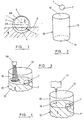
- FIG. 1 The preferred form of hollow insert for use with the present invention is shown in Figure 1 and is in the nature of a hollow capsule 1 having a substantially plain spherical outer surface 2 and defining a substantially plain surface spherical secondary chamber 3.
- the spheres of the surface 2 and chamber 3 are eccentric whereby the sphere of the outer surface 2 has its centre indicated at 2A whilst the spherical chamber 3 has its centre indicated at 3A.
- the effect of this eccentricity is to provide the capsule 1 with a wall thickness which varies progressively over the surface of the sphere so that the capsule will have a thickened wall region 4 and a thin wall region 5.
- the thick wall region 4 and relative increase in weight effectively provided over that region provides a ballasting effect so that when the capsule is floated in a beverage 6 containing gas in solution it will adopt and maintain a particular orientation with the heavier ballasting region 4 submerged in the beverage 6.
- Extending through the wall of the capsule 1 is a restricted aperture 7 by which the secondary chamber 3 communicates with the outside of the capsule.
- the aperture 7 is formed in the capsule so that when the capsule is floating, the aperture is directed substantially horizontally slightly beneath the surface of the beverage 6 and remote from the bottom of the capsule.
- the capsule is conveniently formed from two moulded half shells which are bonded or otherwise secured together along a split line which, in Figure 1, is in a plane extending perpendicularly to the plane of the drawing and through the centres 2A and 3A.
- the beverage 6 containing gas in solution is to be packaged in a primary chamber 13 of a cylindrical metallic can a cylindrical shell for which is shown at 10 (Figure 2) comprising a base 11 and an open top 12.
- the open topped container provided by the shell 10 will be displaced along a filling and canning line which may, substantially, be of conventional form subject to minor modifications for placement of the hollow insert or capsule 1.
- a capsule 1 is dropped into the primary chamber 13 following which the primary chamber is charged with the beverage 6 from a nozzle 6A as shown in Figure 3 so that the capsule 1 floats on the surface of the beverage and rises in the container 10 as the volume of beverage within the primary chamber increases.
- a headspace 15 is formed within which is located the capsule 1 floating on the beverage with its restricted aperture 7 submerged.
- a dose 16 ( Figure 4) of liquid nitrogen (derived from a cryogenic unit 17 in conventional manner) is deposited in the headspace 15 and rapidly evaporates. Evaporation of the liquid nitrogen dose 16 serves two purposes; firstly it flushes atmospheric air from the headspace 15 to alleviate contamination/oxidation of the beverage in the sealed package and secondly it pressurises the headspace when the open top 12 of the container is closed and sealed.
- the restricted aperture 7 is submerged in the beverage 6 during the filling stages shown in Figures 3 and 4, the aperture 7 is so small that, under prevailing atmospheric pressure, a negligible amount, if any, beverage 6 enters the secondary chamber 3 during the short period of the filling stages of Figures 3 and 4.
- the open topped container 10 moves onto a carousel 18A which rotates to displace the container circumferentially as a whole (as shown in the direction of arrow 18 in Figure 5) whilst simultaneously subjecting the container to rotation about the upstanding axis of its cylindrical wall - (the latter rotation being indicated by the arrow 19 in Figure 5).
- an end wall or cap 20 is located to close the open top 12 and the rotation of the can in the direction of arrow 19 is to facilitate sealing of the top end wall 20 to the cylindrical wall of the container 10 by a conventional seaming operation with a seaming unit 21. Whilst the top end wall 20 is being sealed to close the open top of the container 10, the liquid nitrogen dose 16 continues to evaporate and the pressure of gas in the headspace 15 progressively increases.
- the capsule 1 is subjected to a centrifugal force displacing it over the surface of the beverage 6 and relative to the container 10 as indicated by the arrow 24 in Figure 5. Following from this centrifugal force the capsule 1 is caused to abut the cylindrical side wall of the container 10.
- the sealed package may cease its rotary motion and move off the carousel causing the capsule 1 to fall into its lowered or floating position in which it is orientated by its ballasting to locate the restricted aperture 7 submerged in the beverage 6.
- the capsule 1 will have attained its raised position prior to the pressure in the headspace 15 increasing sufficiently to cause beverage to enter the secondary chamber 3 through the restricted aperture - it is appreciated however that a minimal amount of beverage or froth may enter the capsule 1 - at least to ensure that in its natural floating position the restricted aperture 7 is submerged with the insert 1 in the same orientation as that in which it initially floats on the beverage 6.
- beverage or froth may enter the capsule 1 as the contents of the package pass through the final stage of coming into equilibrium following removal of the beverage package from the carousel 18, however the total volume of the beverage which may enter the secondary chamber 3 as the sealed package comes into equilibrium is appreciably less than the volume of such beverage which would otherwise have entered the secondary chamber 3 had the insert not have been subjected to gas pressure from the headspace 15 whilst in its raised position.
- the top wall 20 which is sealed to the container is provided with a ring pull 25 (or other convenient means for opening the package).
- a ring pull 25 or other convenient means for opening the package.
- the headspace 15 is reduced to atmospheric pressure through the opening created by the ring pull.
- a pressure differential develops whereby the pressure of gas greater than atmospheric within the secondary chamber 3 of the capsule causes fluid in the secondary chamber to be ejected from the capsule by way of the restricted aperture 7 to provide a jetting effect 26 into the beverage 6.
- This jetting effect results in gas being liberated from solution in the beverage for the development of froth 27 in the headspace.
- the fluid that is ejected from the capsule through the restricted aperture 7 to effect in froth development is predominantly or wholly gas although it is appreciated that a relatively small amount of beverage or froth may also be ejected through the aperture 7.
- the secondary chamber 3 of the capsule contains gas under pressure with minimal, if any, beverage it is important to ensure that the restricted aperture 7 is in its raised position for a substantial period from the commencement of and during pressurisation of the headspace 15.
- the abutment between the capsule 1 and the cylindrical wall of the open topped container 10 under the centrifugal force 24 that is applied to the capsule will usually create sufficient lift to displace the capsule to its raised position
- the open topped container 10 can be modified to facilitate the lifting of the capsule to its raised position.
- Figure 7 where the wall of the container 10 is provided with an annular external recess 30 that extends about the periphery of the cylindrical wall and presents an internal upwardly directed ramp surface 31.
- the ramp surface 31 is located so that as the capsule 1 abuts the side wall of the container 10, it can co-operate with the ramp surface 31 to ride up that surface (as shown by arrow 32) in response to the centrifugal force 24 to lift the capsule relative to the beverage 6, causing the restricted aperture 7 to emerge from the beverage as the capsule approaches its raised position.
- the ramp surface 31 may be provided by an angled skirt or similar fitment (not shown) carried within the container.
- the capsule may carry or be impregnated with magnetic material 7A by which the capsule may be attracted to a permanent magnet or an electro magnet 33 (see Figure 8) to hold the capsule in its raised position as the headspace 15 is pressurised following the liquid nitrogen dosing.
- a permanent magnet or an electro magnet 33 see Figure 8 to hold the capsule in its raised position as the headspace 15 is pressurised following the liquid nitrogen dosing.
- the capsule is shown being held in its raised position by the electro magnet 33 as the open top of the container is being sealed to the cylindrical side wall 10 by the seaming unit 21.
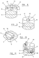
- a hollow insert shown at 50 with its restricted aperture 7 is initially secured to the internal surface of the cylindrical wall of the container 10 at a position that will correspond to the headspace 15.
- the container 10 With the insert 50 so secured the container 10 is charged with beverage 6 and subjected to the pressurisation and sealing stages similar to those previously discussed with reference to Figures 4 and 5.
- the insert 50 is released from the side wall 10 to drop into the beverage 6 and adopt its floating or lowered position.
- the hollow insert 50 is best seen in Figure 10 in its floating position with the restricted aperture 7 submerged.
- the purpose of the insert 50 is identical to that of the capsule 1 although its shape has been changed as convenient for temporary attachment to the container wall.
- the insert 50 has a part cylindrical surface 51 which corresponds to the cylindrical internal surface of the open topped container 10 to which it may be secured in face-to-face contact by a food grade adhesive.
- the part of the insert 50 projecting from the surface 51 may be part cylindrical (say conforming to the lower half of the capsule shown in Figure 1) with a side wall of varying thickness to provide the required ballasting.
- the capsule 50 may be released from the side wall 10 by massaging of that side wall, by a shock force or by subjecting the package to heat, for example during pasteurisation of the beverage in the package, where the adhesive is of a thermally degradable kind.
- Figure 11 shows the package containing the insert 50 reacting upon being opened to cause gas at a pressure greater than atmospheric to be ejected from the insert for the resultant jet to liberate gas from solution in the beverage 6 for the development of froth.
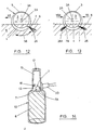
- Figure 12 shows the spherical capsule 1 in operation to create the gas jet 26 during opening of the package and it will be seen that the jetting effect 26 will impart a horizontal thrust to the capsule 1 causing it to be displaced in the direction of arrow 55 over the surface of the beverage 6. Furthermore, the thrust from the jetting effect 26 is located below the centre of the spherical surface 2 and is arranged to cause a rotary motion to be imparted to the capsule 1 in the direction of arrow 56 whereby the capsule effectively exhibits rotation about a horizontal axis. During this rotary motion the fluid jet 26 is displaced arcuately through the beverage 6 to progressively increase its penetration into the depth of the beverage from that shown in Figure 12.
- the jetting effect 26 causes gas to be liberated from solution in the beverage 6 over a depth of the beverage which may be far greater than that which would otherwise be attained (without the capsule exhibiting its rotary motion).
- this arrangement it may be possible to liberate gas in solution from a major proportion of the beverage in the container and thereby create a considerable head of froth (as may be regarded as desirable for stout and ale).
- Figure 13 shows a modified form of the capsule 1 whereby two restricted apertures 7 and 7B are provided, the two restricted apertures being located directly opposite to each other.
- the restricted aperture 7B serves the same function as the aperture 7 in so far as when the beverage package is opened and the capsule 1 is subjected to a pressure differential, gas under pressure is ejected as a jet 26A from the restricted aperture 7B for froth development.
- the jetting effect 26A provides a horizontal thrust 55A on the capsule 1 which directly opposes and counteracts the horizontal thrust 55 which is applied to the capsule by the jet effect 26.
- the capsule 1 in Figure 13 is restrained from rotating about a substantially horizontal axis (in the manner previously discussed with reference to Figure 12) and the generally horizontally directed opposed jets 26 and 26A are restricted to liberating gas from solution in the beverage 6 over a relatively shallow region of the beverage 6 so that a relatively small amount of froth will develop in the headspace 15.
- a relatively large or deep volume of the beverage beneath the jets 26 and 26A may retain gas in solution to provide a sparkle effect when the beverage is dispensed into a transparent glass (as may be considered desirable for lager).
- Figure 14 shows a container in the form of a glass bottle 10 immediately prior to its open top 12 being sealed (usually by a crown closure) and in which the hollow insert/capsule 1 is temporarily retained in its raised position by attraction with an electromagnet 33 in a similar manner to that shown in Figure 8.
Landscapes
- Engineering & Computer Science (AREA)
- Mechanical Engineering (AREA)
- Chemical & Material Sciences (AREA)
- Dispersion Chemistry (AREA)
- Vacuum Packaging (AREA)
- Details Of Rigid Or Semi-Rigid Containers (AREA)
- Packging For Living Organisms, Food Or Medicinal Products That Are Sensitive To Environmental Conditiond (AREA)
- Containers Opened By Tearing Frangible Portions (AREA)
- Packages (AREA)
Claims (22)
- Verfahren zum Verpacken eines Getränks mit in Lösung befindlichem Gas darin, umfassend das Vorsehen eines oben offenen Behälters mit einer Primärkammer und das Auffüllen der Primärkammer mit dem Getränk, um einen Luftraum zu bilden, das Anordnen eines hohlen Einsatzes mit einer Sekundärkammer und einer begrenzten Öffnungsanordnung in der Primärkammer, durch die die Sekundärkammer mit der Primärkammer verbunden wird und Fluid in der Sekundärkammer in das Getränk zur Schaumbildung auf dem Getränk ausgestoßen werden soll, wobei der hohle Einsatz auf dem Getränk in der Primärkammer schwimmen kann und, wenn er im Behälter angeordnet ist, in einer Ausrichtung getrimmt ist, bei der die begrenzte Öffnungsanordnung in das Getränk eingetaucht ist, wenn der Einsatz auf der Oberfläche des Getränks schwimmt, das Verschließen der offenen Oberseite, um die Primärkammer abzudichten, und das Unterdrucksetzen des Luftraums bis zu einem Druck, der größer als der atmosphärische ist, das Anordnen des hohlen Einsatzes im Luftraum in einer erhöhten Position, in der er in Bezug auf die Oberfläche des Getränks während des Unterdurcksetzens erhöht ist, um die begrenzte Öffnungsanordnung mit dem Luftraum zu verbinden, und um in der Sekundärkammer ein unter Druck gesetztes Fluid vorzusehen, das ein Gas unter Druck aufweist, das von der Primärkammer abgeleitet wird und nach dem Unterdrucksetzen des Fluids der Sekundärkammer, und das Anordnen des hohlen Einsatzes in einer niedrigen Position, um auf dem Getränk mit der begrenzten Öffnungsanordnung in dem Getränk eingetaucht zu schwimmen, so daß, wenn der Luftraum zum atmosphärischen Druck geöffnet wird, durch die Druckabnahme in dem Luftraum ein Druckgefälle entsteht, das das Fluid, das Gas unter Druck enthält, in der Sekundärkammer dazu veranlaßt, über die begrenzte Öffnungsanordnung ausgestoßen zu werden, um in das Getränk der Primärkammer zu strömen, und so daß dieses Ausstoßen das Gas in gelöster Form veranlaßt, sich in dem Getränk zur Schaumbildung auf dem Getränk freizusetzen.
- Verfahren nach Anspruch 1, umfassend
das Anordnen des hohlen Einsatzes in die Primärkammer, so daß der Einsatz in seiner niedrigeren Position auf dem Getränk schwimmt, und das anschließende Anheben des Einsatzes in seine erhöhte Position zum Unterdrucksetzen der Sekundärkammer. - Verfahren nach Anspruch 2, umfassend
das Anordnen des hohlen Einsatzes in die Primärkammer vor dem Auffüllen der Primärkammer mit Getränk, so daß der hohle Einsatz auf dem Getränk schwimmt, um in der Primärkammer aufzusteigen, wenn das Getränkevolumen darin während der Bildung des Luftraumes zunimmt. - Verfahren nach Anspruch 2 oder 3, umfassend
das Beaufschlagen des hohlen Einsatzes mit einer horizontal gerichteten Kraftkomponente relativ zum Behälter, um den Einsatz zum Anlegen an eine Wand des Behälters zu veranlassen, wobei dieses Anlegen den Einsatz dazu veranlasst, sich in seine erhöhte Position zu verschieben. - Verfahren nach Anspruch 4, bei dem
die Wand des Behälters eine Rampenfläche aufweist, mit der der Einsatz durch das Anlegen zusammenwirkt, und die Rampenfläche das Anheben des Einsatzes in seine erhöhte Position unterstützt. - Verfahren nach einen der Ansprüche 2 bis 5, umfassend
das Beaufschlagen des hohlen Einsatzes mit einer oder der horizontal gerichteten Kraftkomponente, wobei diese Kraft durch das Beaufschlagen des Einsatzes mit einer Zentrifugalkraft infolge der Drehung des Behälters entsteht, und wobei die Zentrifugalkraft den Einsatz dazu veranlasst, sich in seine erhöhte Position zu verschieben. - Verfahren nach Anspruch 6, bei dem
der Behälter etwa zylindrisch ist, und eine aufrechte Achse hat, um die er gedreht wird, um den Einsatz mit einer Zentrifugalkraft zu beaufschlagen. - Verfahren nach Anspruch 6 oder 7, bei dem
der Behälter in Drehung versetzt wird, um die Zentrifugalkraft während des Verschließens des offenen oberen Endes durch einen Verschließ- bzw. Falzvorgang zu erzeugen. - Verfahren nach Anspruch 2 oder 3, umfassend
das Beaufschlagen des hohlen Einsatzes mit einer vertikal gerichteten Kraftkomponente, um den Einsatz von seiner niedrigeren Position in seine erhöhte Position durch die magnetische Anziehungskraft des Einsatzes zu verschieben. - Verfahren nach Anspruch 1, umfassend
zunächst das Anordnen des hohlen Einsatzes in die Primärkammer in seiner erhöhten Position und das Beibehalten dieser Position wenigstens während des anfänglichen Unterdrucksetzens des Luftraums. - Verfahren nach Anspruch 10, umfassend
zunächst das Anordnen des hohlen Einsatzes in seiner erhöhten Position, bevor die Primärkammer mit dem Getränk gefüllt wird. - Verfahren nach Anspruch 10 oder 11, umfassend
das Anordnen des hohlen Einsatzes in seiner anfänglich erhöhten Position durch das vorübergehende Festhalten des Einsatzes an der Wand des Behälters. - Verfahren nach Anspruch 12, bei dem
die Wand, an der der Einsatz festgehalten wird, eine aufrechte Seitenwand des Behälters ist. - Verfahren nach Anspruch 12 oder 13, bei dem
der Einsatz vorübergehend mittels eines Klebstoffes festgehalten wird. - Verfahren nach Anspruch 14, bei dem
der Einsatz von dem Klebstoff durch das Erhitzen des Klebstoffes gelöst wird, um in seine niedrigere Position zu fallen. - Verfahren nach Anspruch 15, bei dem
die Hitze während des Pasteurisieren des Getränks in der abgedichteten Verpackung entsteht. - Verfahren nach Anspruch 12 oder 13, bei dem
der Einsatz vorübergehend magnetisch festgehalten wird. - Verfahren nach einen der vorhergehenden Ansprüche, bei dem
der hohle Einsatz aus einer Plastikkapsel besteht, die eine einzelne Kammer aufweist, die die Sekundärkammer bildet und die von einer im wesentlichen glatten Oberfläche gebildet wird, um frei von Hindernissen zu sein. - Verfahren nach einen der vorhergehenden Ansprüche, umfassend
das Trimmen des Einsatzes durch bereichsweises Beschweren des Einsatzes, das aus einen lokal verdickten Bereich der Wanddicke des Einsatzes resultiert. , - Verfahren nach einen der vorhergehenden Ansprüche, bei dem
der Einsatz eine im wesentlichen kugelförmige äußere Oberfläche hat und die Sekundärkammer im wesentlichen kugelförmig ist, wobei der Mittelpunkt der Sekundärkammer zum Mittelpunkt der Kugel der äußeren Oberfläche exzentrisch ist, um den Einsatz mit einer Wand mit einer verändernden Dicke zur versehen, deren Veränderungen der Dicke dazu dienen, den Einsatz in eine Position zu trimmen, in der er dann auf dem Getränk, mit der begrenzten Öffnungsanordnung in des Getränk eingetaucht, schwimmt. - Verfahren nach einen der vorhergehenden Ansprüche, umfassend
das Unterdrucksetzen des Luftraums durch Zuführen einer Dosis flüssigen Stickstoffs, das Abdichten der offenen Oberseite und das Ermöglichen, daß der Inhalt des Behälters ins Gleichgewicht kommt. - Verfahren nach Anspruch 21, umfassend
das Beibehalten des Einsatzes in seiner erhöhten Position während des Verschließens der offenen Oberseite und wenigstens, bis ein wesentlicher Anteil des flüssigen Stickstoffs verdampft ist, um den Luftraum bis auf einen Hauptanteil seines endgültigen Drucks unter Druck zu setzen.
Applications Claiming Priority (2)
| Application Number | Priority Date | Filing Date | Title |
|---|---|---|---|
| GB9700242A GB2321042B (en) | 1997-01-08 | 1997-01-08 | A method of packaging a beverage containing gas in solution and a beverage package |
| GB9700242 | 1997-01-08 |
Publications (3)
| Publication Number | Publication Date |
|---|---|
| EP0854089A2 EP0854089A2 (de) | 1998-07-22 |
| EP0854089A3 EP0854089A3 (de) | 1998-12-23 |
| EP0854089B1 true EP0854089B1 (de) | 2002-04-03 |
Family
ID=10805647
Family Applications (1)
| Application Number | Title | Priority Date | Filing Date |
|---|---|---|---|
| EP97309758A Expired - Lifetime EP0854089B1 (de) | 1997-01-08 | 1997-12-03 | Verfahren zum Verpacken eines gelöstes Gas enthaltenden Getränkes |
Country Status (10)
| Country | Link |
|---|---|
| US (1) | US6551638B1 (de) |
| EP (1) | EP0854089B1 (de) |
| JP (1) | JP3957382B2 (de) |
| AU (1) | AU730356B2 (de) |
| CA (1) | CA2223602C (de) |
| DE (1) | DE69711589T2 (de) |
| DK (1) | DK0854089T3 (de) |
| ES (1) | ES2175288T3 (de) |
| GB (1) | GB2321042B (de) |
| NZ (1) | NZ329388A (de) |
Cited By (1)
| Publication number | Priority date | Publication date | Assignee | Title |
|---|---|---|---|---|
| WO2004037706A2 (de) | 2002-10-23 | 2004-05-06 | Adelholzener Alpenquellen Gmbh | Verfahren und vorrichtung zum abfüllen eines getränks in einen getränkebehälter, getränkebehälter |
Families Citing this family (15)
| Publication number | Priority date | Publication date | Assignee | Title |
|---|---|---|---|---|
| GB2350097B (en) | 1999-05-17 | 2002-11-13 | Guinness Ltd | Packaging for beverage containing gas in solution |
| DE20106836U1 (de) * | 2001-04-19 | 2001-09-27 | RPC Bramlage GmbH, 49393 Lohne | Einsatz für unter Druck stehende Flüssigkeitsbehälter, insbesondere Getränkebehälter |
| USD492403S1 (en) | 2003-01-06 | 2004-06-29 | Given Imaging Ltd. | Spherical capsule |
| US20060021989A1 (en) * | 2004-07-29 | 2006-02-02 | David Friedman | Beverage container for immersing food |
| US20100009052A1 (en) * | 2006-07-14 | 2010-01-14 | Dr. Pepper/Seven Up, Inc. | Beverage containing nitrous oxide and carbon dioxide |
| US20080286421A1 (en) * | 2006-07-14 | 2008-11-20 | Delease Patricia | Foam-creating compositions, foaming beverage compositions, and methods of preparation thereof |
| US8448809B2 (en) | 2007-10-15 | 2013-05-28 | Millercoors, Llc | Thermal barrier liner for containers |
| CA2752775C (en) * | 2007-10-15 | 2013-03-12 | Coors Brewing Company | Insulated beverage container and method |
| US8297072B2 (en) * | 2007-10-16 | 2012-10-30 | Millercoors, Llc | Container incorporating integral cooling element |
| US8336729B2 (en) * | 2007-10-15 | 2012-12-25 | Millercoors, Llc | Thermal barrier liner for containers |
| US20100303971A1 (en) * | 2009-06-02 | 2010-12-02 | Whitewave Services, Inc. | Producing foam and dispersing creamer and flavor through packaging |
| US10966440B2 (en) * | 2019-01-05 | 2021-04-06 | Foremost Technologies and Products, Inc. | High pressure processing of foods and food supplements |
| KR102487259B1 (ko) | 2021-01-04 | 2023-01-11 | 하이트진로 주식회사 | 서징효과가 향상된 주류 및 음료의 위젯 및 이를 포함하는 주류 제품 및 음료 제품의 제조방법 |
| US11912556B2 (en) * | 2021-01-07 | 2024-02-27 | Kevin D. McGushion | Methods, systems and devices for protecting a surface of a container from exposure to additives |
| KR102768809B1 (ko) * | 2021-12-10 | 2025-02-19 | 주식회사 루왁코리아 | 거품층을 형성하는 액상 커피 |
Family Cites Families (14)
| Publication number | Priority date | Publication date | Assignee | Title |
|---|---|---|---|---|
| US5066184A (en) * | 1989-01-18 | 1991-11-19 | Mitsubishi Jukogyo Kabushiki Kaisha | Method for seaming packed cans |
| USD318225S (en) * | 1989-07-24 | 1991-07-16 | Henry J. Cassai | Beverage can |
| IE70665B1 (en) * | 1989-11-22 | 1996-12-11 | Whitbread & Co Plc | Carbonated beverage container |
| JP3012092B2 (ja) * | 1991-11-06 | 2000-02-21 | 臼井 芳雄 | 圧潰性缶 |
| US5230203A (en) * | 1992-04-10 | 1993-07-27 | Coors Brewing Company | Apparatus and method for providing sealed containers filled with a liquid |
| US5346095A (en) * | 1993-06-01 | 1994-09-13 | Deal Richard E | Beverage can |
| GB2295600B (en) * | 1993-07-30 | 1997-02-05 | Scottish & Newcastle Plc | Device for producing a head on a beverage |
| GB9315830D0 (en) | 1993-07-30 | 1993-09-15 | Pa Consulting Services | Improvements in and relating to head generation on beverages |
| GB9316197D0 (en) * | 1993-08-05 | 1993-09-22 | Pa Consulting Services | Improvements in and relating to head generation on beverages |
| AU674985B2 (en) * | 1993-07-30 | 1997-01-16 | Courage Limited | Beverage enhancer |
| SG42972A1 (en) * | 1993-08-12 | 1997-10-17 | Heineken Tech Services | Beverage container |
| DK0719230T3 (da) * | 1993-09-28 | 1998-05-04 | American National Can Co | Skumdannende indsats til en drikkebeholder |
| DK0739300T3 (da) * | 1994-01-21 | 1999-03-22 | Whitbread & Co Ltd | Drikkevarebeholder |
| GB2305159A (en) * | 1995-09-14 | 1997-04-02 | Ryford Ltd | A floating device for generating froth, a container for the device, and a method of filling the container |
-
1997
- 1997-01-08 GB GB9700242A patent/GB2321042B/en not_active Expired - Fee Related
- 1997-12-03 DE DE69711589T patent/DE69711589T2/de not_active Expired - Fee Related
- 1997-12-03 ES ES97309758T patent/ES2175288T3/es not_active Expired - Lifetime
- 1997-12-03 EP EP97309758A patent/EP0854089B1/de not_active Expired - Lifetime
- 1997-12-03 DK DK97309758T patent/DK0854089T3/da active
- 1997-12-10 NZ NZ329388A patent/NZ329388A/en not_active IP Right Cessation
- 1997-12-19 AU AU48524/97A patent/AU730356B2/en not_active Ceased
- 1997-12-29 US US08/999,342 patent/US6551638B1/en not_active Expired - Lifetime
-
1998
- 1998-01-07 CA CA002223602A patent/CA2223602C/en not_active Expired - Lifetime
- 1998-01-07 JP JP00170598A patent/JP3957382B2/ja not_active Expired - Lifetime
Cited By (1)
| Publication number | Priority date | Publication date | Assignee | Title |
|---|---|---|---|---|
| WO2004037706A2 (de) | 2002-10-23 | 2004-05-06 | Adelholzener Alpenquellen Gmbh | Verfahren und vorrichtung zum abfüllen eines getränks in einen getränkebehälter, getränkebehälter |
Also Published As
| Publication number | Publication date |
|---|---|
| US6551638B1 (en) | 2003-04-22 |
| JPH10194291A (ja) | 1998-07-28 |
| NZ329388A (en) | 1998-06-26 |
| AU4852497A (en) | 1998-07-16 |
| DE69711589D1 (de) | 2002-05-08 |
| DK0854089T3 (da) | 2002-07-29 |
| EP0854089A2 (de) | 1998-07-22 |
| ES2175288T3 (es) | 2002-11-16 |
| DE69711589T2 (de) | 2002-09-26 |
| EP0854089A3 (de) | 1998-12-23 |
| CA2223602C (en) | 2003-03-18 |
| GB2321042A (en) | 1998-07-15 |
| AU730356B2 (en) | 2001-03-08 |
| GB9700242D0 (en) | 1997-02-26 |
| JP3957382B2 (ja) | 2007-08-15 |
| CA2223602A1 (en) | 1998-07-08 |
| GB2321042B (en) | 2001-03-28 |
Similar Documents
| Publication | Publication Date | Title |
|---|---|---|
| US6551638B1 (en) | Method of packaging a beverage containing gas in solution and a beverage package | |
| EP0227213B1 (de) | Getränkeverpackung und Verfahren zum Verpacken eines gelöstes Gas enthaltenden Getränkes | |
| EP0577284B1 (de) | Eine Verpackung für ein Getränk und ein Verfahren zum Verpacken eines Getränkes | |
| JPH05507455A (ja) | 炭酸飲料用容器 | |
| JPH0542976A (ja) | 飲料パツケージ容器と飲料パツケージ方法 | |
| EP0712368B1 (de) | Einsatz für behälter für kohlensäurehaltige getränke | |
| CA2128625A1 (en) | Carbonated beverage container | |
| WO1995005326A1 (en) | Carbonated beverage container | |
| AU743336B2 (en) | In-container sachet | |
| GB2293166A (en) | Beverage bottle with froth forming insert | |
| CN204822683U (zh) | 含有溶解气体的饮料的饮料包装 | |
| WO1995003982A2 (en) | Device for producing a head on a beverage | |
| AU6217194A (en) | A beverage container with means for frothing the beverage | |
| JPH08507028A (ja) | 炭酸飲料用容器 | |
| WO1995019925A1 (en) | Beverage container | |
| MXPA00012362A (en) | In-container sachet |
Legal Events
| Date | Code | Title | Description |
|---|---|---|---|
| PUAI | Public reference made under article 153(3) epc to a published international application that has entered the european phase |
Free format text: ORIGINAL CODE: 0009012 |
|
| AK | Designated contracting states |
Kind code of ref document: A2 Designated state(s): BE DE DK ES FR GB IE NL |
|
| AX | Request for extension of the european patent |
Free format text: AL;LT;LV;MK;RO;SI |
|
| 17P | Request for examination filed |
Effective date: 19980622 |
|
| PUAL | Search report despatched |
Free format text: ORIGINAL CODE: 0009013 |
|
| AK | Designated contracting states |
Kind code of ref document: A3 Designated state(s): AT BE CH DE DK ES FI FR GB GR IE IT LI LU MC NL PT SE |
|
| AX | Request for extension of the european patent |
Free format text: AL;LT;LV;MK;RO;SI |
|
| AKX | Designation fees paid |
Free format text: BE DE DK ES FR GB IE NL |
|
| 17Q | First examination report despatched |
Effective date: 20000608 |
|
| RTI1 | Title (correction) |
Free format text: A METHOD OF PACKAGING A BEVERAGE CONTAINING GAS IN SOLUTION |
|
| GRAG | Despatch of communication of intention to grant |
Free format text: ORIGINAL CODE: EPIDOS AGRA |
|
| RTI1 | Title (correction) |
Free format text: A METHOD OF PACKAGING A BEVERAGE CONTAINING GAS IN SOLUTION |
|
| GRAG | Despatch of communication of intention to grant |
Free format text: ORIGINAL CODE: EPIDOS AGRA |
|
| GRAH | Despatch of communication of intention to grant a patent |
Free format text: ORIGINAL CODE: EPIDOS IGRA |
|
| GRAH | Despatch of communication of intention to grant a patent |
Free format text: ORIGINAL CODE: EPIDOS IGRA |
|
| REG | Reference to a national code |
Ref country code: GB Ref legal event code: IF02 |
|
| GRAA | (expected) grant |
Free format text: ORIGINAL CODE: 0009210 |
|
| AK | Designated contracting states |
Kind code of ref document: B1 Designated state(s): BE DE DK ES FR GB IE NL |
|
| REF | Corresponds to: |
Ref document number: 69711589 Country of ref document: DE Date of ref document: 20020508 |
|
| RAP2 | Party data changed (patent owner data changed or rights of a patent transferred) |
Owner name: GUINNESS LIMITED |
|
| REG | Reference to a national code |
Ref country code: IE Ref legal event code: FG4D |
|
| NLT2 | Nl: modifications (of names), taken from the european patent patent bulletin |
Owner name: GUINNESS LIMITED |
|
| REG | Reference to a national code |
Ref country code: DK Ref legal event code: T3 |
|
| ET | Fr: translation filed | ||
| REG | Reference to a national code |
Ref country code: ES Ref legal event code: FG2A Ref document number: 2175288 Country of ref document: ES Kind code of ref document: T3 |
|
| PLBE | No opposition filed within time limit |
Free format text: ORIGINAL CODE: 0009261 |
|
| STAA | Information on the status of an ep patent application or granted ep patent |
Free format text: STATUS: NO OPPOSITION FILED WITHIN TIME LIMIT |
|
| 26N | No opposition filed |
Effective date: 20030106 |
|
| PGFP | Annual fee paid to national office [announced via postgrant information from national office to epo] |
Ref country code: DK Payment date: 20050531 Year of fee payment: 8 Ref country code: DE Payment date: 20050531 Year of fee payment: 8 Ref country code: BE Payment date: 20050531 Year of fee payment: 8 Ref country code: NL Payment date: 20050531 Year of fee payment: 8 Ref country code: FR Payment date: 20050531 Year of fee payment: 8 |
|
| PGFP | Annual fee paid to national office [announced via postgrant information from national office to epo] |
Ref country code: ES Payment date: 20050628 Year of fee payment: 8 |
|
| PG25 | Lapsed in a contracting state [announced via postgrant information from national office to epo] |
Ref country code: ES Free format text: LAPSE BECAUSE OF NON-PAYMENT OF DUE FEES Effective date: 20051205 |
|
| PG25 | Lapsed in a contracting state [announced via postgrant information from national office to epo] |
Ref country code: BE Free format text: LAPSE BECAUSE OF NON-PAYMENT OF DUE FEES Effective date: 20051231 |
|
| PG25 | Lapsed in a contracting state [announced via postgrant information from national office to epo] |
Ref country code: DK Free format text: LAPSE BECAUSE OF NON-PAYMENT OF DUE FEES Effective date: 20060102 |
|
| PG25 | Lapsed in a contracting state [announced via postgrant information from national office to epo] |
Ref country code: NL Free format text: LAPSE BECAUSE OF NON-PAYMENT OF DUE FEES Effective date: 20060701 Ref country code: DE Free format text: LAPSE BECAUSE OF NON-PAYMENT OF DUE FEES Effective date: 20060701 |
|
| REG | Reference to a national code |
Ref country code: DK Ref legal event code: EBP |
|
| PG25 | Lapsed in a contracting state [announced via postgrant information from national office to epo] |
Ref country code: FR Free format text: LAPSE BECAUSE OF NON-PAYMENT OF DUE FEES Effective date: 20060831 |
|
| NLV4 | Nl: lapsed or anulled due to non-payment of the annual fee |
Effective date: 20060701 |
|
| REG | Reference to a national code |
Ref country code: FR Ref legal event code: ST Effective date: 20060831 |
|
| REG | Reference to a national code |
Ref country code: ES Ref legal event code: FD2A Effective date: 20051205 |
|
| BERE | Be: lapsed |
Owner name: *GUINNESS LTD Effective date: 20051231 |
|
| PGFP | Annual fee paid to national office [announced via postgrant information from national office to epo] |
Ref country code: IE Payment date: 20161227 Year of fee payment: 20 |
|
| PGFP | Annual fee paid to national office [announced via postgrant information from national office to epo] |
Ref country code: GB Payment date: 20170105 Year of fee payment: 20 |
|
| REG | Reference to a national code |
Ref country code: GB Ref legal event code: PE20 Expiry date: 20171202 |
|
| REG | Reference to a national code |
Ref country code: IE Ref legal event code: MK9A |
|
| PG25 | Lapsed in a contracting state [announced via postgrant information from national office to epo] |
Ref country code: GB Free format text: LAPSE BECAUSE OF EXPIRATION OF PROTECTION Effective date: 20171202 |
|
| PG25 | Lapsed in a contracting state [announced via postgrant information from national office to epo] |
Ref country code: IE Free format text: LAPSE BECAUSE OF EXPIRATION OF PROTECTION Effective date: 20171203 |